Three Phase Electricity Explained


Three Phase Electricity

Three phase electricity delivers power using three alternating currents that are offset in phase. It provides consistent and efficient energy for industrial, commercial, and high-load applications, improving stability and reducing conductor size.


What is Three Phase Electricity?

Three phase electricity is a power system that uses three alternating currents, each offset by 120 degrees, to deliver constant power flow.

✅ Delivers more efficient and stable power than single-phase systems

✅ Ideal for large motors, commercial buildings, and industrial equipment

✅ Reduces conductor material and energy loss over long distances


Three phase voltage, frequency and number of wires

Three phase electricity is the dominant method of electrical power generation, transmission, and distribution across the industrialized world. Unlike single-phase systems, which rely on a single alternating current, three-phase systems use three separate currents, each 120 degrees out of phase with the others. This setup provides a consistent and balanced power flow, making it significantly more efficient for high-demand applications, such as motors, transformers, and large-scale infrastructure. Understanding the difference between alternating current and direct current is essential to grasp how three-phase systems deliver constant power using offset waveforms.


Understanding the Concept

At the heart of a three-phase system are three sinusoidal waveforms, evenly spaced to maintain a continuous flow of energy. When one phase reaches its peak, the others are in different parts of their cycle, ensuring that at any given moment, some power is being delivered. This creates what is known as constant power transfer, a major advantage over single-phase systems that experience power dips between cycles. Since three-phase systems rely heavily on accurate current flow measurement, it’s important to know what ammeters measure and how they help monitor system balance.

For industrial and commercial operations, this stability translates to increased energy efficiency, extended equipment lifespan, and reduced operating costs. Large electric motors, for example, run more smoothly on three-phase power, which avoids the surging and vibration commonly associated with single-phase inputs.


A Brief History

Three phase electricity wasn’t invented by a single person but emerged through the contributions of several pioneers in the late 19th century. Galileo Ferraris in Italy, Nikola Tesla in the United States, and Mikhail Dolivo-Dobrovolsky in Europe all played crucial roles in developing and refining the idea of three-phase alternating current. Tesla’s patents and Dolivo-Dobrovolsky’s practical systems laid the groundwork for what is now a global standard. Engineers use wattmeters to accurately measure real power in three-phase systems, while Watts Law helps calculate the relationships between voltage, current, and power.


Wye and Delta Configurations

Three-phase systems are typically wired in one of two configurations: the Wye (Y) or Delta (Δ) configuration. Each has specific advantages depending on the application:

  • In a Wye connection, each phase is tied to a central neutral point, allowing for multiple voltage levels within the same system. This is common in both commercial and residential applications, where both high and low voltages are required.

  • A Delta connection utilizes a closed loop with no neutral, a configuration commonly found in industrial setups. It delivers the same voltage between all phases and is ideal for running large motors without needing a neutral return path.

One of the most important relationships in these configurations is the √3 ratio between line voltage and phase voltage, a fundamental aspect that engineers use in calculating load, cable sizing, and protective device coordination.


Technical Benefits

Three-phase systems have built-in advantages that go beyond stability. Because the sum of the three phase currents is zero in a balanced load, a neutral wire is often unnecessary. This reduces the amount of conductor material needed, lowering costs and simplifying design. Additionally, three-phase motors naturally create a rotating magnetic field, eliminating the need for external circuitry to start or maintain rotation.

Another major benefit is that power output remains consistent. In single-phase systems, power drops to zero twice per cycle, but three-phase systems deliver non-pulsating power, which is especially important in sensitive or precision equipment. The function of a busbar is especially important in three-phase distribution panels, helping to manage multiple circuit connections efficiently.


Where and Why It’s Used

While most homes use single-phase electricity, three-phase is the standard in virtually all commercial and industrial environments. Factories, data centers, hospitals, and office buildings rely on it to power everything from HVAC systems and elevators to conveyor belts and industrial machines.

Three-phase is also common in electric vehicle (EV) charging stations and renewable energy systems, where efficient, high-capacity delivery is essential. If you're working with three-phase motors or transformers, knowing the role of a conductor and how electrical resistance affects current flow is fundamental to efficient design.

For sites that only have access to single-phase power, phase converters—whether rotary or digital—can simulate three-phase conditions, enabling them to operate three-phase equipment. This flexibility has made three-phase solutions accessible even in remote or rural areas. Three-phase systems often operate at medium voltage, especially in commercial settings, and their stability can reduce the risks of ground faults.


Voltage Levels and Color Codes

Depending on the region, the standard line and phase voltages vary. In North America, typical voltage values include 120/208 volts and 277/480 volts, whereas in Europe and much of Asia, 230/400 volts is more common. Wiring color codes also differ: red/yellow/blue in Europe, black/red/blue in North America, and other variations depending on the country's electrical code. These standards ensure safety, compatibility, and ease of troubleshooting.


The Global Standard for Power

Three-phase electricity is not just a technical solution; it is the foundation of modern electrical infrastructure. Its ability to deliver large amounts of power efficiently, safely, and reliably has made it the system of choice for more than a century. From powering the machines that build our world to the systems that keep us connected, three-phase electricity remains indispensable.


Related Articles


Related News

Voltage Drop Explained

Voltage drop occurs when electrical voltage decreases as current flows through a conductor. It can cause poor equipment performance, energy loss, and overheating. Discover how selecting the proper wire size and material can help minimize voltage drop in electrical systems.

Power Quality Analysis Training

Power Factor Training

Request a Free Power Quality Training Quotation


What is Voltage Drop?

Voltage drop (VD) is a common issue in electrical systems where the voltage (V) at the end of a circuit is lower than at the beginning due to resistance in the wiring.

✅ A decrease in V along a wire or circuit due to resistance or impedance

✅ Leads to reduced equipment performance and higher energy consumption

✅ Prevented by proper wire sizing, shorter runs, and low-resistance materials


Voltage Drop Definition

Voltage drop can lead to inefficient equipment operation or even failure. Solving electrical potential drop involves ensuring proper wire sizing, minimizing long-distance wiring runs, and using materials with lower resistance. Calculating the voltage drop for specific circuits and adjusting the installation accordingly helps maintain optimal performance and prevent power loss.

Any length or size of wires will have some resistance, and running a current through this dc resistance will cause the voltage to drop. As the length of the cable increases, so does its resistance and reactance increase in proportion. Hence, circuit V drop is particularly a problem with long cable runs, for example, in larger buildings or on larger properties such as farms. This technique is often used when properly sizing conductors in any single-phase, line-to-line electrical circuit. This can be measured with a voltage drop calculator.

Electrical cables have a carrying capacity of current that always presents inherent resistance, or impedance, to the flow of current. Voltage drop is measured as the amount of loss which occurs through all or part of a circuit due to what is called cable "impedance" in volts.

Too much resistance in wires, otherwise known as " excessive voltage drop ", in a cable's cross-sectional area can cause lights to flicker or burn dimly, heaters to heat poorly, and motors to run hotter than normal and burn out. This condition causes the load to work harder with less energy, pushing the current.


Voltage Drop per 100 Feet of Copper Wire (Single Phase, 60 Hz, 75°C, 120V Circuit)

(Values are approximate, in volts, for a 2% limit)

Wire Size (AWG) Max Current (Amps) Max Distance (Feet) Voltage Drop (at max distance)
14 15 50 2.4 V
12 20 60 2.4 V
10 30 80 2.4 V
8 40 100 2.4 V
6 55 130 2.4 V
4 70 160 2.4 V
2 95 200 2.4 V
1/0 125 250 2.4 V


Key Takeaways

  • Larger wires (lower AWG numbers) carry more current with less VD.

  • Longer distances require thicker wires to stay within VD limits.

  • A 2% VD is often used as a conservative design target in electrical systems.


How is this solved?

To decrease the voltage drop in a circuit, you need to increase the size (cross-section) of your conductors – this is done to lower the overall resistance of the cable length. Certainly, larger copper or aluminum cable sizes increase the cost, so it’s essential to calculate the voltage drop and determine the optimum wire size that will reduce voltage drop to safe levels while remaining cost-effective.


How do you calculate voltage drop?

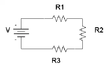
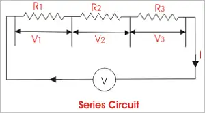
Voltage drop refers to the loss of electricity that occurs when current flows through a resistance. The greater the resistance, the greater the voltage drop. To check the voltage drop, use a voltmeter connected between the points where the voltage drop is to be measured. In DC circuits and AC resistive circuits, the total of all the voltage drops across series-connected loads should add up to the V applied to the circuit (Figure 1).


Fig. 1. Measuring voltage drops across loads

Read our companion article Voltage Drop Calculator. For more information, see our article: Voltage Drop Formula.

Each load device must receive its rated power to operate properly. If not enough is available, the device will not operate as it should. You should always be certain that the V you are going to measure does not exceed the range of the voltmeter. This may be difficult if the V is unknown. If such is the case, you should always start with the highest range. Attempting to measure a V higher than the voltmeter can handle may cause damage to the voltmeter. At times you may be required to measure a V from a specific point in the circuit to ground or a common reference point (Figure 8-15). To do this, first connect the black common test probe of the voltmeter to the circuit ground or common. Then connect the red test probe to whatever point in the circuit you want to measure.

To accurately calculate the drop for a given cable size, length, and current, you need to accurately know the resistance of the type of cable you’re using. However, AS3000 outlines a simplified method that can be used.

The table below is taken from AS3000 electrical code, which specifies ‘Amps per %Vd‘ (amps per percentage VD) for each cable size.  To calculate the dop for a circuit as a percentage, multiply the current (amps) by the cable length (metres); then divide this Ohm number by the value in the table.

For example, a 30m run of 6 mm² cable carrying 3-phase 32A will result in a 1.5% drop: 32A × 30m = 960A / 615 = 1.5%.

Learn more about real-world voltage drop issues on our Voltage Dropping in Power Quality page.


Related Pages


View more

Free Electricity Explained

Free electricity is power generated without fuel costs, typically from solar or wind sources. After setup, systems like solar panels can reduce or eliminate bills through net metering, helping promote sustainability and energy independence for homes and businesses.


What is Free Electricity?

Free electricity refers to energy that costs nothing to generate after initial setup, typically utilizing natural sources.

✅ Harnesses renewable energy sources like solar panels and wind turbines

✅ Reduces or eliminates long-term electricity costs

✅ Promotes sustainable and eco-friendly living solutions


The Reality of Free Electricity

True “free electricity” does not exist in the sense of unlimited, no-cost power available without investment. However, generating your electricity at home through solar panels or small wind systems can reduce your reliance on the power grid and lower your energy bills significantly, sometimes to zero. This cost reduction is what many people mean when they refer to "free electricity."

Purchasing and installing a solar power system is not free, but it pays off over time. It’s a long-term investment that benefits both the environment and your finances. Some homeowners even reach the point where their solar systems generate more electricity than they use.

In such cases, through a policy known as net metering, these homeowners can send excess electricity back to the power grid and receive compensation from their utility company.


What is Net Metering?

Net metering is a billing arrangement that allows consumers who generate their own electricity to send excess power back to the grid and receive credit for it. Here’s how it works:

  • Net metering allows you to sell the electricity produced by a solar system on your home back to the electric power grid.

  • Net Metering occurs when your meter spins backwards as solar electricity is being produced, storing the excess energy on the grid.

  • Once energy is actually being consumed, your meter spins forward to collect the energy that has been saved on your electric power grid.

  • For the energy that you do not consume, the electric utility will compensate you. If you get paid enough money from the electricity that you don't use and sell to them, then that profit can be used to pay for your existing consumption, making it essentially free electricity.

Some utilities offer cash payments for the surplus, while others provide energy credits that reduce your bill. Either way, your electricity costs can be significantly reduced—and in some cases, essentially eliminated.


Key Considerations for a Free Electricity System

A few things to watch out for when choosing to invest in a Free Electricity solar power system.

  • You must conserve your energy consumption to ensure that you don't exceed the amount of solar energy produced.

  • By exceeding the amount of power generated many times for the grid or saved, you are then charged regular rates for electricity provided by your electric utility.

  • You must watch your solar energy production. Keep track of the daily energy production of your system.

  • Check your utility bill each month to ensure that you are credited or reimbursed for any and all extra energy generated.

  • To control your electricity usage, consider using a time-of-use electric meter to further capitalize on your investment.


Utility Policies Vary

Not all utility companies offer generous net metering. Some may only provide energy credits, while others pay wholesale rates for your excess electricity. It's essential to check with your local utility to understand how they handle customer-generated power.

While the term “free electricity” is somewhat misleading, it does accurately reflect the very real possibility of generating low-cost or no-cost power after your initial system is installed. Through renewable energy systems and programs like net metering, homeowners can reduce or eliminate energy bills and make a lasting contribution to a cleaner, more sustainable future.


Related Articles


View more

Electrical Resistance Explained

Electrical resistance is the opposition to the flow of electric current in a material. It is measured in ohms (Ω) and depends on the conductor’s length, thickness, material, and temperature.


What is Electrical Resistance?

Electrical resistance is a fundamental concept in engineering that defines how much a material opposes the flow of electric current. Measured in ohms (Ω), resistance (Ω) plays a crucial role in circuit design, power distribution, and electronic applications.

✅ Measured in ohms (Ω) and calculated using Ohm’s Law

✅ Influenced by material, length, area, and temperature

✅ Key factor in circuit safety, design, and energy loss


Think of electricity moving like water through a pipe. If the pipe is narrow or obstructed, less water flows through it. Similarly, in a wire or conductor, certain materials make it harder for electrons to move freely. This obstruction results in energy loss, often seen as heat.

The ease or difficulty of electric charge movement depends on the conductivity of a material. Metals like copper allow current to flow easily, while rubber or glass inhibit it entirely. This behavior plays a key role in how systems are designed and protected. Discover how resistors are used in circuits to manage voltage and protect components by providing controlled resistance.


Electrical Resistance – Example Values by Material/Component

Material/Component Approx. Resistance Notes
Copper wire (1 meter, 1mm²) ~0.017 ohms Very low resistance, ideal for conductors
Aluminum wire (1m, 1mm²) ~0.028 ohms Higher resistance than copper
Iron wire (1m, 1mm²) ~0.10 ohms Often used in heating elements
Nichrome wire (1m, 1mm²) ~1.10 ohms High-resistance alloy used in toasters and heaters
Human body (dry skin) 1,000–100,000 ohms Varies greatly with moisture and contact
Incandescent light bulb ~240 ohms (cold) Resistance increases when hot
Resistor (carbon film) Fixed (e.g., 220 ohms) Used to control current in circuits
Air (dry) ~1 trillion ohms (insulator) Excellent natural insulator unless ionized
Superconductor 0 ohms Only at extremely low temperatures (near absolute zero)


Electrical Resistance Definition

Several factors affecting electrical resistance include the type of material, temperature, and the dimensions of the conductor. When an electric charge moves through a material, its ease of flow depends on the material’s conductivity. A high-conductivity material allows charges to move more freely, resulting in lower resistance. The resistance of a conductor increases with its length and decreases with its cross-sectional area. Therefore, the resistance of a wire is directly related to both its physical properties and the material from which it is made. The resistance of a conductor depends heavily on its length and cross-sectional area, as outlined in our resistance formula breakdown.

This opposing property is quantified using Ohm’s Law:

R = V / I

Where:

  • R is the resistive value in ohms

  • V is voltage (volts)

  • I is current (amperes)

Another useful expression involves material properties:

R = ρ × (L / A)

Where:

  • ρ is resistivity (material-specific)

  • L is length

  • A is cross-sectional area

These formulas show that the longer or thinner the conductor, the harder it is for current to move through it.


Unit of Electrical Resistance – The Ohm (Ω)

The ohm is the SI unit of resistance, named after German physicist Georg Ohm. One ohm is defined as the resistance between two points of a conductor when a potential difference of one volt causes a current of one ampere to flow.

Common multiples:

  • kΩ (kilo-ohm) = 1,000 ohms

  • MΩ (mega-ohm) = 1,000,000 ohms

Resistance can be measured using a multimeter, and is especially important in designing and troubleshooting power  and electronic circuits. To understand how voltage and resistance interact in a circuit, see our guide on Ohm’s Law.


Ohm’s Law and Circuit Function

Ohm’s Law helps us understand how voltage, current, and resistance relate. For example:

  • Increase the resistive load, and current drops.

  • Increase voltage with fixed resistance, and current rises.

These principles help control energy flow, prevent overloads, and design efficient systems.


Measuring and Expressing Opposition

The ohm (Ω) is the standard unit used to quantify this phenomenon. One ohm means that a current of one ampere flows when one volt is applied. Components with fixed values, like resistors, are labelled accordingly—e.g., 100 Ω, 1 kΩ, or 1 MΩ.

To measure the current-limiting capacity of a material, a digital multimeter is used. It applies a small voltage and calculates the resulting current flow to determine the opposition level. If you're working with different wire types, explore the unit of electrical resistance for conversion insights and resistance ranges.


Real-World Examples of Resistance

  • Heating Elements: Toasters, ovens, and electric heaters utilize high-resistance materials, such as nichrome wire.

  • Power Transmission: Long-distance wires are designed with low resistance to reduce energy loss as heat.

  • Electronic Components: Resistors regulate current in circuits, protecting components from overload.

For real-world scenarios involving current flow, our article on voltage drop explains how resistance affects electrical efficiency over distance.


Factors Affecting Electrical Resistance

  • The resistance of a conductor depends on:

    • Material – copper vs. aluminum vs. nichrome

    • Length – longer wires restrict current more

    • Thickness – wider wires allow easier flow

    • Temperature – many materials resist current more when heated

    Thus, the resistance of a wire can vary dramatically depending on where and how it’s used. Materials with high conductivity (like silver or copper) allow electrons to move with minimal restriction, whereas poor conductors like rubber greatly hinder charge movement.


Superconductors – Zero Resistance?

In some materials, when cooled to extremely low temperatures, resistance drops to zero. These superconductors enable electricity to flow without energy loss, but their use is limited to specialized fields, such as MRI machines or experimental power lines, due to cost and cooling requirements.


Frequently Asked Questions


What causes electrical resistance?

It results from collisions between electrons and atoms in a conductor, which convert energy into heat.


What is the formula for calculating it?

 R = V/I or R = ρ × (L / A)


How is it measured?

With a multimeter in ohms (Ω), using a small test voltage and measuring current. Learn how instruments like a digital multimeter are used to measure opposition to current flow in electrical systems.


Why is this concept important?

It controls current flow, prevents damage, and enables functions like heating or dimming.


Can resistance ever be zero?

Yes—in superconductors under specific extreme conditions.

Electrical resistance is a foundational concept in understanding how electricity behaves in materials and systems. From household wiring to high-voltage power lines and sensitive electronics, it plays a crucial role in determining safety, efficiency, and performance. For a broader view on electric flow and material response, read about electrical conductivity and current electricity.


Related Articles


View more

Ampere's Law Explained

Ampere’s Law describes the relationship between magnetic fields and electric currents, a fundamental concept in electromagnetism. It explains how current produces a magnetic force, guiding the design of circuits, solenoids, coils, and transformers in electrical engineering.


What is Ampere’s Law?

Ampere's Law is a fundamental principle in electromagnetism that describes the relationship between electric current and the resulting magnetic field.

✅ It states that the magnetic field around a closed path is proportional to the electric current passing through it.

✅ It is a fundamental principle of electromagnetism, linking current and magnetic flux.

✅ Used in analyzing coils, solenoids, transformers, and magnetic circuits.

Named after the French physicist André-Marie Ampère, this powerful principle helps us understand the behaviour of magnetic fields generated by electric currents. It is crucial to develop the numerous technologies we use on a daily basis. Understanding Ampere's Law is easier when explored alongside related concepts in basic electricity, which provide the foundation for electrical theory.

The principle states that the line integral of a magnetic field (B) around a closed loop is equal to the product of the permeability of free space (μ₀) and the net electric current (I) passing through the loop. This can be mathematically represented as:

∮ B⋅dl = μ₀I


Ampere’s Law at a Glance

Aspect Explanation Example / Application
Definition Magnetic field around a closed loop is proportional to the net electric current passing through it. Helps calculate fields in wires, coils, solenoids.
Formula ∮ B · dl = μ₀I (line integral of magnetic field equals permeability × current). Used in physics and engineering calculations.
Relation to Biot-Savart Law Both describe magnetic fields from current. Biot-Savart handles complex geometries; Ampere’s Law suits symmetrical setups. Magnetic field around a straight wire vs. irregular current paths.
Relation to Faraday’s Law Ampere’s Law: current → magnetic field. Faraday’s Law: changing magnetic field → induced EMF. Motors, generators, induction coils.
Role in Maxwell’s Equations One of the four fundamental equations of electromagnetism. Describes interaction of electric and magnetic fields.
Key Devices Guides design of solenoids, transformers, inductors, motors, and generators. Power systems, telecommunications, energy conversion.
Real-World Impact Essential to modern technology relying on electromagnetism. Smartphones, computers, power grids, antennas.


Ampere’s Law and Magnetism

The principle can be applied to determine the magnetic field around current-carrying wires and other conductive materials, as well as within various electrical systems. It is an essential part of Maxwell's equations, a set of four equations that serve as the foundation of classical electromagnetism. These equations relate electric and magnetic fields to their sources (electric charges and currents) and describe how they propagate through space. The connection between electricity and magnetism is central to electromagnetism, where Ampere’s Law works hand-in-hand with Faraday’s Law to explain induction.

It calculates magnetic fields through the Biot-Savart Law, a mathematical expression that relates the magnetic field produced by a steady electric current to the current's geometry. Both principles have specific applications, with the Biot-Savart Law being more suitable for cases with intricate current configurations. At the same time, it is typically employed when dealing with symmetrical setups.

Ampere’s Law has numerous real-life applications, especially in developing and understanding devices and systems that involve electromagnetism. For example, it is used in the design of transformers, inductors, and solenoids, as well as in various applications such as telecommunications systems, motors, and generators. By applying it, engineers can predict and control the magnetic fields generated in these devices, ensuring they function optimally and efficiently.


Gauss’ Law and Electric Fields Around a Circle of Radius

When studying electromagnetism, a common problem is analyzing the behavior of electric fields around a symmetric object, such as a circle of radius r or a sphere. Gauss’ Law is especially powerful in such cases, because it states that the electric flux through a closed surface is proportional to the net charge enclosed. This means the distribution of field lines can be calculated without solving complex integrals directly.

For a uniformly charged circle of radius r, the electric field at a point along the axis can be derived by considering the superposition of contributions from each charge element. The result reveals that the electric field depends on both the radius of the circle and the distance from the observation point. This demonstrates how Gauss’ Law simplifies problems with high symmetry.

Mathematically, the relationship is expressed as:

∮ E · dA = Q / ε₀

Here, E represents the vector field of the electric field, dA is the infinitesimal area vector on the closed surface, Q is the enclosed charge, and ε₀ is the permittivity of free space. By applying this principle, one can determine that electric fields radiate symmetrically outward from charges, with strength diminishing with distance according to the geometry of the surface considered.

The application of Gauss’ Law in analyzing a circle of radius r is connected to Ampere’s Law, as both emphasize symmetry and integration around closed paths. Where Ampere’s Law links magnetic fields to current, Gauss’ Law links electric fields to charge, and together they form part of Maxwell’s equations, the foundation of electromagnetism.


Relationship between Ampere's Law and Faraday's Law

The relationship between Ampere's Law and Faraday's Law of electromagnetic induction is apparent in the phenomenon of electromagnetic induction itself. When a changing magnetic field induces an electric current in a conductive material, the resulting magnetic field generated by this electric current, in turn, affects the overall magnetic field. It helps us understand how these interacting magnetic fields behave and influence each other.

Ampere's Law and its applications in various devices and systems enable numerous technological advancements. For instance, when designing motors and generators, engineers can utilize the principle to optimize the magnetic field within the device, resulting in higher efficiency and improved performance. Ampere’s Law is also linked to the behavior of capacitance and inductance, both of which are essential in circuits and energy storage systems.

In the telecommunications realm, it helps explain the propagation of electromagnetic waves in cables and antennas. It enables engineers to design systems that minimize signal loss and maximize data transfer rates, ensuring that our smartphones, computers, and other devices remain connected and up-to-date.

By understanding the magnetic field lines and the interaction between electric current and magnetic fields, Ampere's Law opens doors to scientific discovery and innovation in numerous fields. From determining the magnetic field at a distance to the thumb rule and hand rule applications, this fundamental principle plays a crucial role in shaping the world of electromagnetism and the technology that surrounds us.


Electromagnetism

It is a cornerstone of electromagnetism that helps us understand the relationship between electric current and how it creates a magnetic field. It is a vital component of Maxwell's equations and intricately connected to other principles, such as Faraday's Law and Biot-Savart's Law. Ampere's Law has numerous applications in real-life scenarios and is essential for the functioning of many devices and systems that rely on electromagnetism. Its significance in the development of technology cannot be overstated, as it continues to drive scientific discovery and innovation. For students exploring fundamentals, the history of concepts like what is electricity and its evolution in electricity history provides valuable context to Ampere’s discoveries.


How does Ampere’s Law relate to Faraday's Law and Biot-Savart Law?

They are all essential principles in electromagnetism that describe various aspects of the interaction between electric currents and magnetic fields. Although each addresses different aspects, these are interrelated, forming a more comprehensive understanding of electromagnetism.

It describes the relationship between an electric current and its generated magnetic field. Mathematically, it states that the line integral of the magnetic field (B) around a closed loop is proportional to the net electric current (I) passing through the loop:

∮ B⋅dl = μ₀I

Ampere’s Law is useful for calculating magnetic fields in highly symmetrical situations, such as around straight wires, loops, or solenoids.

Faraday's Law: Faraday's Law of Electromagnetic Induction describes how a changing magnetic field induces an electromotive force (EMF) in a conductor. Mathematically, it states that the induced EMF is proportional to the rate of change of the magnetic flux (ΦB) through a closed loop formed by the conductor:

EMF = -dΦB/dt

Faraday's Law is fundamental to understanding the operation of devices such as generators, transformers, and induction motors, which rely on converting mechanical and electrical energy.

The Biot-Savart Law calculates the magnetic field at any point in space due to a specific current distribution. Mathematically, it can be expressed as:

dB = (μ₀ / 4π) * (Idl × r̂) / r²

The Biot-Savart Law is particularly useful for calculating magnetic fields in complex current configurations without symmetry.


Ampere's Law and Biot-Savart Law

Ampere's Law and Biot-Savart Law: Both deal with the magnetic field generated by an electric current. While the first is useful for calculating magnetic fields in symmetric situations, the Biot-Savart Law applies to a wider range of configurations, including those with intricate geometries. It can be derived from the Biot-Savart Law for specific symmetric situations.


Ampere's Law and Faraday's Law

Ampere's Law and Faraday's Law: These laws are related through Maxwell's equations, which connect electric and magnetic fields. While the first deals with the magnetic field generated by a steady electric current, Faraday's Law deals with the induced EMF resulting from a changing magnetic field. Both laws contribute to our understanding of electromagnetic phenomena and play a role in operating devices that rely on electromagnetism.

The Biot-Savart Law enables us to determine the magnetic field generated by a specific current distribution. Faraday's Law describes how a changing magnetic field can induce an EMF. In cases where the magnetic field changes due to a varying current, the Biot-Savart Law can be used to calculate the magnetic field, and then Faraday's Law can be applied to determine the induced EMF.

All three are interconnected principles in electromagnetism, each addressing a specific aspect of the interaction between the electric current and the electric field. Together, these form a more comprehensive understanding of electromagnetic phenomena and provide a basis for analyzing and designing various devices and systems that rely on electromagnetism.


Related Articles


View more

Wireless Electricity

Wireless electricity transmits power without wires using electromagnetic fields, such as magnetic resonance or microwave transmission. It enables charging devices remotely, powering sensors, and improving efficiency in smart grids, EVs, and wireless charging systems.


What is Wireless Electricity?

Wireless electricity refers to the transmission of electrical energy without physical conductors like wires.

✅ Powers devices through electromagnetic fields, like inductive coupling

✅ Enables contactless charging in consumer electronics and EVs

✅ Supports smart grids, IoT, and remote sensors with flexible energy delivery

Wireless electricity, also known as wireless power transmission, was first conceptualized by Nikola Tesla, a pioneer in the field of alternating current (AC) electricity. Tesla’s groundbreaking experiments at Colorado Springs in 1899 showcased how power could be transmitted without wires using a magnetic field. He used a Tesla coil to transmit 100 million volts of high power over a distance of 26 miles, wirelessly powering 200 light bulbs and an electric motor. His vision was to develop a wireless system capable of transmitting power over long distances with minimal energy loss.

Tesla’s system relied on a high-frequency alternating current and magnetic resonance to transmit power wirelessly. His experiments with the Tesla coil laid the groundwork for modern wireless technologies, including short-range wi

reless power transmission systems, such as wireless charging pads and Wi-Fi routers. Wireless charging pads today utilize magnetic fields to transmit power to devices, a concept similar to Tesla’s idea of harnessing the Earth’s resonance to transmit power over longer distances. Tesla’s vision extended beyond short-range wireless systems—he dreamed of a global system where energy flows freely through the air without requiring a direct line of sight.

Tesla’s experiments also demonstrated the efficiency of wireless systems. The Tesla coil could transmit power wirelessly to fluorescent light bulbs even when they were several feet away from the coil. This concept of powering devices wirelessly has evolved over time, with companies like Wi-Charge developing systems to transmit power wirelessly to small devices. In Tesla’s time, he envisioned a world where any amount of power could be transmitted wirelessly across the globe. However, financial struggles eventually led to the abandonment of his wireless power transmission projects, including the unfinished Wardenclyffe tower on Long Island. Devices powered wirelessly still rely on efficient energy flow, making concepts such as electrical resistance and impedance crucial to design and performance.

Despite Tesla’s challenges, modern advancements have kept his vision alive. Short-range wireless power transmission systems, like those used in Wi-Fi routers and wireless charging pads, are now commonplace. These technologies utilize magnetic fields to transmit power wirelessly over short distances, offering a practical solution for wirelessly charging devices such as smartphones and laptops. Wi-Charge is exploring the potential of wirelessly charging devices without requiring close contact, enabling more flexible and efficient energy distribution. Tesla’s coil and modern systems like Wi-Charge operate based on resonant principles, closely related to inductance and capacitance.


Modern Innovations in Wireless Electricity

Recent breakthroughs have brought Tesla’s dream closer to reality:

  • In 2024, DARPA successfully transmitted 800 watts of power over 5 miles using a laser beam—enough to make popcorn at the receiver site.

  • KAIST in South Korea demonstrated the ability to charge 40 smartphones at once using magnetic resonance over a distance of 5 meters.

  • Detroit’s Corktown district now hosts a functioning inductive charging roadway, allowing EVs to charge wirelessly while in motion.

These examples show that wireless electricity is no longer a distant vision but a rapidly advancing technology with real-world applications. Concepts such as watts, volts, and amperes remain fundamental even in advanced wireless systems.


Types of Wireless Power Transmission Technologies

Technology Type Description and Use Cases
Inductive Coupling Short-range charging pads for phones, laptops, and wearables
Magnetic Resonance Mid-range charging for larger devices and multiple receivers simultaneously
Microwave Transmission Long-range point-to-point energy transfer; used in research and satellites
Laser Power Beaming High-efficiency focused beams for distant targets; demonstrated by DARPA
Infrared Light (Wi-Charge) Contactless charging for smart locks and IoT devices


Applications of Wireless Electricity

  • Consumer Electronics: Wireless charging pads and smart home devices are now common.

  • Electric Vehicles (EVs): Inductive charging roads and parking pads reduce dependency on cable stations.

  • Medical Implants: Enables powering of implants and biosensors without invasive wiring.

  • Remote Sensors: In agriculture, factories, and infrastructure, wireless power extends sensor life.

  • Smart Grids: Flexible energy distribution for remote locations and emergency response.


Challenges and Future Outlook

Despite its promise, wireless electricity faces challenges:

  • Efficiency drops over distance

  • Alignment issues in inductive systems

  • Line-of-sight limitations in laser and IR systems

  • Safety regulations for high-power beaming

However, the future is promising. Emerging materials, such as metamaterials and metasurfaces, are enhancing transmission efficiency. AI-enhanced beam control, dynamic alignment systems, and frequency-agnostic receivers are under development.

From Tesla's early experiments to DARPA's record-setting laser transmission, wireless electricity is evolving into a transformative force. As the technology matures, its applications will expand, powering a world that may one day be truly wire-free.


Related Articles


View more

Resistance in Series Explained

Resistance in series refers to the arrangement of individual resistors in a circuit, where the current flows through each resistor end to end. In this configuration, the total resistance (R) of the circuit is equal to the sum of the individual resistances, also known as the equivalent R.


What is Resistance in Series?

Resistance in series refers to a circuit configuration where resistors are arranged in a single path:

✅ Total resistance is the sum of all resistors in the circuit

✅ The same current flows through each resistor

✅ Voltage divides across each resistor based on its value

To calculate the total R in a series circuit, the individual resistances of each resistor are added together. The formula to calculate the equivalent resistance in a series connection is Rtotal = R1 + R2 + R3 + ..., where R1, R2, R3, and so on, represent the individual resistances of each resistor in the circuit.

Ohm's law also applies to series circuits, where the current through each resistor is the same, but the voltage across each resistor is proportional to its R. The total voltage across the series combination of resistors equals the sum of the voltage drops across each resistor.

It is essential to note that the total resistance in a series circuit is always greater than the resistance of any individual resistor in the circuit, due to the cumulative effect of each resistor's resistance.

On the other hand, resistors connected in parallel result in a parallel circuit. The equivalent R of a parallel circuit is calculated differently from a series connection. Instead of adding the individual resistances, the reciprocal of each R is added, and the resulting value is inverted to obtain the equivalent resistance.


R in Series - Parallel

When you place R-I-S, their ohmic values add up arithmetically to reach the total (or net) R.

We can connect a series of resistors (equal to the sum of the individual resistances of a parallel circuit), all having identical ohmic values, in parallel sets of series networks or series sets of parallel networks. When we do either of these things, we create a series-parallel network that can significantly increase the total power-handling capacity of the network compared to the power-handling capacity of a single parallel resistor.


Fig. 4-14. Three resistors in series. 

Sometimes, the total single equivalent R of the combination circuit in a series-parallel network equals the value of any one of the resistors. This always happens if the parallel branches or parallel combinations of the connection components are all identical and are arranged in a network called an n-by-n (or n x n) matrix. That means when n is a whole number, we have n series sets of n resistors connected in parallel, or else we have n parallel sets of n resistors connected in series in the circuit. These two arrangements yield the same practical result for electrical circuits.

A combination of series parallel combinations array of n by n resistors, all having identical ohmic values and identical power ratings, will have n2 times the power-handling capability of any resistor by itself. For example, a 3 x 3 series-parallel matrix of 2 W resistors can handle up to 32 x 2 = 9 x 2 = 18 W. If we have a 10 x 10 array of 1/2 W resistors, then it can dissipate up to 102 x 1/2 = 50 W. We multiply the power-handling capacity of each individual resistor by the total number of resistors in the matrix.

The above-described scheme works if, but only if, all of the resistors have identical ohmic values according to ohms law and identical power-dissipation ratings in terms of total voltage drops when the sum of the voltage drops across each resistor. If the resistors have values that differ even a little bit from one another, one of the components will likely draw more current than it can withstand, so that it will burn out, no matter the voltage source. Then the current distribution in the network will change further, increasing the likelihood that a second resistor will fail, and maybe more.

If you need a resistor that can handle 50 W, and a certain series-parallel connection of the network will handle 75 W, that's fine. But you should not "push your luck" and expect to get away with using a network that will handle only 48 W in the same application. You should allow some extra tolerance, say 10 per cent over the minimum rating. If you expect the network to dissipate 50W, you should build it to handle 55W or a bit more. You don't have to use "overkill," however. You'll waste resources if you cobble together a network that can handle 500W when you only expect it to cope with 50W—unless that's the only convenient combination you can make with available resistors.


Related Articles


View more

Sign Up for Electricity Forum’s Newsletter

Stay informed with our FREE Newsletter — get the latest news, breakthrough technologies, and expert insights, delivered straight to your inbox.

Electricity Today T&D Magazine Subscribe for FREE

Stay informed with the latest T&D policies and technologies.
  • Timely insights from industry experts
  • Practical solutions T&D engineers
  • Free access to every issue

Live Online & In-person Group Training

Advantages To Instructor-Led Training – Instructor-Led Course, Customized Training, Multiple Locations, Economical, CEU Credits, Course Discounts.

Request For Quotation

Whether you would prefer Live Online or In-Person instruction, our electrical training courses can be tailored to meet your company's specific requirements and delivered to your employees in one location or at various locations.