Direct Current Explained

By R.W. Hurst, Editor


direct current

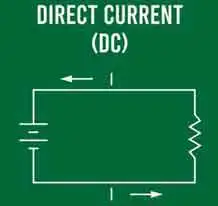
Direct current (DC) is a steady flow of electric charge in one direction, widely used in batteries, electronics, and power supply systems. Unlike alternating current, it provides constant voltage, making it vital for circuits, devices, and renewable energy applications.


What is Direct Current?

Direct current (DC) is an electric charge that flows consistently in one direction through a conductor.

✅ Provides constant voltage for stable operation

✅ Powers batteries, electronics, and renewable systems

✅ Differs from alternating current by unidirectional flow

Direct current (DC) plays an essential role in electrical power. It is a type of electrical flow where the flow of electric charge remains constant and does not change direction. DC differs from alternating current (AC), periodically reversing direction as the voltages and amperage vary with time. Direct current is often compared with alternating current, which reverses direction periodically and dominates modern transmission systems.

One of the most well-known proponents of direct current was Thomas Edison, who competed with George Westinghouse, an advocate for alternating current, in the late 19th century. Their competition, known as the "War of the Currents," ultimately led to the widespread adoption of AC systems, which are more suitable for long-distance, high-voltage transmission. However, this does not diminish the importance and numerous applications of direct current in modern technology. To better understand how DC works, it helps to review basic electricity concepts such as charge, voltage, and resistance.

A direct current power supply, often found in electronic devices, converts AC power from the power grid into DC power. This conversion process ensures a constant voltage that meets the device's requirements. The conversion is achieved through transformers, rectifiers, and capacitors, which stabilize the voltage and smooth out the electrical signal.

Direct current has various advantages and disadvantages. One of its main advantages is the ability to provide stable, constant power, essential for devices such as computers, smartphones, and other sensitive electronics. Additionally, DC power has lower losses in the form of heat dissipation compared to AC power. On the other hand, a significant disadvantage of DC is its limited capacity for long-distance power transmission. It requires larger conductors to maintain efficiency, and the power loss becomes substantial over long distances. The difference between AC and DC has shaped the history of electricity since the “War of the Currents” between Edison and Westinghouse.

DC motors and generators operate through the principle of electromagnetism. A DC motor converts electrical energy into mechanical energy, while a generator turns mechanical energy into electrical energy. The interaction between a magnetic field and the flow of amperage within conductive wires generates a force, causing the motor's rotor to rotate. In the case of a generator, the mechanical motion induces a flow within the conductive wires.

Battery technology heavily relies on direct current, as batteries store and discharge energy in DC power. This is one reason electric vehicles (EVs) use DC motors and batteries for propulsion. In addition, the growing trend towards renewable energy sources, such as solar panels and wind turbines, further highlights the importance of DC power, as these sources initially generate DC power before converting it to AC for grid integration. For a broader context, you can explore electricity fundamentals, which cover both direct and alternating current and their applications.

Both AC and DC currents can be converted and transmitted through specialized equipment. For example, AC can be converted into DC using rectifiers, while DC can be converted back into AC through inverters. The conversion between these two forms of electricity enables the integration of renewable energy sources into the existing power grid. Additionally, it enables the efficient use of energy storage systems, such as batteries. Many renewable energy systems generate DC first, making them a form of alternative electricity that is later converted to AC for grid use.

DC voltage conversion involves changing the voltage level of a direct current without altering its form. This is typically achieved through DC converters, which either step up (increase) or step down (decrease) the voltage. In many electronic devices, DC converters provide the correct voltage levels required for different components to function optimally.

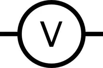
Direct current can be calculated using Ohm's Law, which states that voltage (V) equals the product of flow (I) and resistance (R). The formula is V = I × R. This fundamental principle is crucial for understanding and analyzing electrical circuits, including those involving direct current.

DC is directly related to electrical resistance, since Ohm’s Law determines how voltage, cpnduction, and resistance interact in a circuit.

Devices like rectifiers and inverters rely on principles explained in Ampere’s Law and Biot-Savart Law, which describe the relationship between electricity and magnetism.


Frequently Asked Questions


What is the best formula to calculate DC electrical stream? 

Ohm's Law is the fundamental principle governing the relationship between voltage, flow, and resistance in an electrical circuit. It is named after German physicist Georg Simon Ohm, who formulated the law in the early 19th century. Ohm's Law can be used to calculate direct (DC) electrical current when the voltage and resistance are known.

The formula for Ohm's Law is:

V = I × R

Where:
V = Voltage (volts)
I = Current (amperes or amps)
R = Resistance (ohms)

This formula can be rearranged to calculate the current (I) when voltage (V) and resistance (R) are given:

I = V / R

Using this formula, we can determine the DC electrical energy flowing through a circuit when the voltage across the circuit and the resistance of the circuit are known.

For example, consider a simple DC circuit with a 12-volt voltage source and a 6-ohm resistor. Using the formula for calculating current, we can determine the amperage flowing through the circuit:

I = V / R
I = 12 V / 6 Ω
I = 2 A

Thus, the DC electrical amperage flowing through the circuit is 2 amperes.

To calculate DC electrical stream, apply Ohm's Law by dividing the voltage (V) by the resistance (R) to determine the current (I) in amperes. Ohm's Law is a fundamental principle in electrical engineering, serving as the basis for understanding and analyzing electrical circuits, including those involving direct current.


Are there fewer losses with the direct current than with the alternating current?

Whether there are fewer losses with direct current (DC) than alternating current (AC) depends on the specific application and context. In certain scenarios, DC can have fewer losses, while AC might be more efficient in others. Below are some examples to illustrate this point:

Transmission losses: In long-distance high-voltage power transmission, direct high-voltage current (HVDC) transmission lines can have fewer losses than traditional AC transmission lines. This is because DC transmission lines do not suffer from reactive power losses or the skin effect (which causes higher resistance in AC lines due to the stream flowing mainly on the conductor's surface). Moreover, HVDC lines can be more efficient over long distances as they require only two conductors, while three are needed for AC transmission lines.

Electronic devices: When it comes to electronic devices like computers and smartphones, as well as other sensitive equipment, DC power is often preferred because it provides stable, constant power, resulting in lower losses in the form of heat dissipation. However, these devices need a conversion from the AC power supplied by the grid to the DC power they require. The conversion process may introduce some losses, but DC can be more efficient for these applications once the power is converted.

Electric power transmission over short distances: AC is typically more efficient than DC for shorter distances and lower voltage levels. AC voltage can be easily transformed to different levels using transformers, which are relatively simple and low-loss devices. In contrast, converting DC voltage levels requires more complex and potentially lossy power electronic converters.

The efficiency of direct and alternating currents depends on the specific application and context. For example, DC power can have fewer losses in some cases, such as HVDC transmission lines and sensitive electronic devices. On the other hand, AC is more efficient for short-distance and lower voltage-level transmission, mainly due to the ease of transforming voltage levels using transformers.


Is direct current safer than alternating current?

The safety of direct current (DC) and alternating current (AC) depends on several factors, including voltage, stream levels, and the specific application. However, it is essential to remember that both types of current can be hazardous under specific conditions.

Both charge flow types are generally considered safe when comparing the safety of DC and AC at low voltages and amps. However, some differences in the physiological effects of DC and AC on the human body can make one type of amperage more hazardous than the other under certain conditions:

Muscle contraction: AC can cause muscle contractions that may make it difficult for a person to release a live wire or conductor. In contrast, DC can also cause muscle contractions, but typically only when making or breaking contact with the conductor. This means that once a person is in contact with a DC source, the muscles may not contract continuously, making it easier to let go.

Ventricular fibrillation: AC has a higher probability of causing ventricular fibrillation (a life-threatening heart rhythm disturbance) than DC at the same energy levels. The frequency of AC power, typically 50 or 60 Hz, can interfere with the electrical signals in the heart, leading to this dangerous condition. DC is less likely to cause ventricular fibrillation because it lacks a frequency component.

Skin resistance: Human skin has a higher resistance to DC than to AC, which can result in less amperage flowing through the body when exposed to DC compared to AC at the same voltage levels. However, this difference in resistance is mostly relevant at low voltages, and the risk of injury still exists when dealing with high-voltage DC sources.

Although there are some differences in the effects of DC and AC on the human body, it is essential to understand that both types of amperage can be dangerous when not handled properly. Therefore, safety precautions must always be taken when working with electrical systems, whether they involve direct or alternating current.

Ultimately, the safety of direct and alternating currents depends on the specific situation and proper handling of electrical systems. However, by following established safety protocols, potential risks associated with both types of amperage can be minimized.

Related News

Watt’s Law - Power Triangle

Watt’s Law defines the relationship between power (watts), voltage (volts), and current (amps): Power = Voltage × Current. It’s used in electrical calculations to determine energy usage, system efficiency, and safe equipment ratings in both residential and industrial systems.


What is: Watt’s Law?

Watt’s Law is a fundamental principle in electrical engineering:

✅ Calculates electrical power as the product of voltage and current

✅ Helps design efficient and safe electrical systems

✅ Used in both residential and industrial applications

Watt’s Law is a fundamental principle in electrical engineering that defines the relationship between power, voltage, and current in an electrical circuit. James Watt invented the law. It states that the power (measured in watts) of an electrical device is equal to the product of the voltage (measured in volts) and the current (measured in amperes) flowing through it. In other words, the watt's law formula is expressed as: Power = Voltage × Current. This simple equation is essential for understanding how electrical components consume and distribute energy in a circuit. 

For example, consider a light bulb connected to an electrical circuit. The electrical potential (voltage) pushes the electric charge through the filament of the bulb, creating a flow of electrons (current). As the electrons flow, they generate heat and light, representing the bulb’s power in a circuit. By knowing the voltage and current, you can easily calculate the power output of the bulb. The wattage of the bulb indicates the energy consumed per second.

Practical applications of this formula are vast. This equation is especially useful in designing safe and efficient electrical systems. For instance, designing the wiring for both small devices and large power systems requires a thorough understanding of the relationship between voltage, current, and power. The formula helps ensure that systems are capable of delivering the required energy without causing failures or inefficiencies.

Ohm’s Law and this principle are often used together in electrical engineering. While power focuses on the relationship between voltage and current, Ohm’s Law deals with the relationship between voltage, current, and resistance (measured in ohms). Ohm’s Law states that voltage equals current multiplied by resistance (Voltage = Current × Resistance). By combining Ohm’s Law and this power equation, you can analyze an electrical system more comprehensively. For example, if you know the voltage and resistance in a circuit, you can calculate the current and then determine the power in the circuit. To fully understand Watt's Law, it helps to explore how voltage and current electricity interact in a typical electrical circuit.


Georg Simon Ohm – German physicist and mathematician (1787–1854), known for Ohm's Law, relating voltage, current, and resistance.


What is Watt's Law and how is it used in electrical circuits?

Watt’s Law is a fundamental principle in electrical engineering that defines the relationship between power, voltage, and current in an electrical circuit. The formula is expressed as:

Power (Watts) = Voltage (Volts) × Current (Amperes)

In simpler terms, Watt’s Law states that the electrical power consumed by a device (measured in watts) is the product of the electrical potential difference (voltage) and the current flowing through the circuit. Accurate calculations using Watt’s Law often require a voltage-drop calculator to account for line losses in long-distance wiring. Comparing voltage drop and voltage sag conditions illustrates how slight changes in voltage can have a substantial impact on power output.


James Watt – Scottish inventor and mechanical engineer (1736–1819), whose improvements to the steam engine led to the naming of the watt (unit of power).


How is it used? Watt’s Law is widely used to determine the amount of power an electrical device or system consumes. This is especially important for designing electrical circuits, optimizing power distribution, and ensuring the efficiency of devices. Here are a few examples of how it’s applied:

  • Electrical Circuit Design: Engineers use it to calculate the power consumption of devices and ensure that circuits can handle the expected electrical load. This helps prevent overloads and ensures that the wiring is safe.

  • Power Output Calculations: Using this formula, you can calculate the power output of a generator, appliance, or device, enabling you to match the right components to your system's requirements.

  • Energy Efficiency: Understanding power consumption in appliances and devices helps consumers make informed choices, such as selecting energy-efficient options. Devices like wattmeters and watthour meters measure power and energy usage based directly on the principles of Watt’s Law. For a deeper look at how devices like ammeters help measure current, see how their readings plug directly into Watt’s Law calculations.


How is Watt's Law different from Ohm's Law?

Watt’s Law and Ohm’s Law are both fundamental principles in electrical engineering, but they deal with different aspects of electrical systems:

  • Watt’s Law defines the relationship between power, voltage, and current. It focuses on the amount of energy used by a device in a given circuit. The formula is:

           Power = Voltage × Current

  • Ohm’s Law defines the relationship between voltage, current, and resistance in a circuit. Ohm’s Law explains how the current is affected by the voltage and the resistance present in the circuit. The formula for Ohm’s Law is:

            Voltage = Current × Resistance


Key Differences:

  • Focus: It focuses on power, while Ohm’s Law focuses on the flow of electricity in a circuit, particularly how resistance affects current.

  • Watt’s Law is used to determine the amount of power a device is consuming. Ohm’s Law, on the other hand, is used to calculate current, voltage, or resistance in a circuit depending on the other known variables.

  • Applications: It is applied when designing systems that require power management, such as calculating the power output or efficiency of devices. Ohm’s Law is used more in analyzing how current behaves in a circuit when different resistive elements are present.

By combining both laws, electrical engineers can gain a comprehensive understanding of how electrical systems function, ensuring that devices operate efficiently and safely. When used with Ohm’s Law, Watt's Law enables engineers to analyze both energy consumption and electrical resistance.

One key area of application is in energy consumption. By understanding the voltage and current values for a specific device, engineers can monitor the amount of energy the device consumes. This is especially important for managing energy usage in homes, businesses, and power systems. By applying the formula, you can identify inefficient devices and make more informed decisions about energy efficiency.

In renewable energy systems, such as solar panels and wind turbines, this principle plays a critical role in optimizing energy output. Engineers use the formula to calculate how much electrical energy is being generated and distributed. This is crucial for ensuring that power systems operate efficiently and minimize excess energy loss.

Another practical application of this formula is in the automotive industry. It is used to design vehicle charging systems and battery technologies. For example, electric vehicle (EV) charging stations depend on understanding voltage, current, and power to ensure efficient charging times. Engineers use the equation to calculate the charging capacity required for EV batteries, helping to create optimal charging solutions.

In large facilities like data centers, this Watt’s Law formula is used to ensure power distribution is efficient. By applying the relationship between power, voltage, and current, engineers can effectively manage power systems, thereby reducing energy consumption and operational costs. Proper energy management in data centers is crucial, as high power usage can result in significant energy costs.

This power formula is indispensable for electrical engineers and technicians. The applications of Watt’s Law extend across various industries and are utilized in everything from designing power system wiring to developing renewable energy technologies. By combining Ohm’s Law and this principle, electrical engineers can optimize the performance of electrical components, ensuring energy efficiency and system reliability. Understanding the role of a resistor in a circuit can reveal how power is dissipated as heat, a key concept derived from Watt’s Law.

Finally, visual tools like the Watt's Law triangle are often used to simplify the application of this principle, helping both professionals and students understand how to apply the formula. As technology advances and energy demands grow, this formula remains a key element in electrical engineering, guiding the development of more efficient systems for the future.


Related Articles


View more

Definition of a Rectifier

Definition of a rectifier explains AC to DC conversion using diodes, bridge or full-wave circuits, filters, and regulators to supply stable DC, reduce ripple, and power electronics, chargers, and DC motor drives.


What Is the Definition of a Rectifier?

An explanation of devices that convert AC to DC using diodes and filtering to deliver regulated, low-ripple DC power.

✅ Converts alternating current to direct current via diodes

✅ Topologies: half-wave, full-wave, bridge rectifier

✅ Uses filters and regulators to minimize ripple and stabilize DC


Understanding the definition of a rectifier is fundamental to grasping the complexities of power electronics and electrical engineering. Rectifiers are pivotal in converting AC power to DC power, a critical process for operating numerous electronic devices. By delving into the intricacies of half-wave, full-wave, and bridge rectifiers, as well as the silicon-controlled rectifier, it becomes clear that these devices are crucial in shaping the modern world of electronics. For readers new to the basics, an overview of the difference between AC and DC can clarify foundational concepts.


In electrical engineering, the definition encompasses a vital device that plays a crucial role in converting alternating current (AC) into direct current (DC). It  is an essential component in power electronics. It facilitates the conversion of AC power, commonly used in households and businesses, to DC power that electronic devices rely on. To contextualize this conversion, understanding alternating current behavior in typical distribution systems explains the need for rectification.

They come in various forms, such as diodes, mercury arc valves, and silicon-controlled rectifiers (SCRs). A diode, the most basic rectifying component, allows current to flow in only one direction. This feature helps convert AC power, which alternates direction, to DC power that flows in a single, continuous direction. For measurement and notation conventions, see how DC current is defined and applied in circuit analysis.

AC to DC conversion regulates voltage to create a steady and reliable energy supply. Throughout this conversion, rectifiers often assume different configurations depending on the specific application or requirement. Two popular configurations are the half-wave rectifier and the full-wave rectifier. Downstream stabilization is often handled by a voltage regulator that smooths residual ripple and safeguards loads.

A half-wave type allows only one half of the AC waveform to pass through while blocking the other half. This type is relatively simple and cost-effective but has a few downsides, such as lower efficiency and increased ripple voltage. Ripple voltage refers to the residual periodic variation of the DC output voltage. The result is an unsteady DC output, which might be undesirable in certain applications.

On the other hand, the full-wave type allows both halves of the AC waveform to pass through, effectively doubling the output frequency and reducing the ripple voltage. This configuration improves efficiency and provides a smoother, more consistent DC output voltage. The full-wave type has two primary forms: the center-tap configuration and the bridge rectifier.

The bridge rectifier is a highly efficient configuration that uses four diodes in a specific arrangement. This configuration eliminates the need for a center-tapped transformer, a key component in center-tap full-wave rectifiers, thus reducing overall size and cost. In addition, the bridge rectifier provides better voltage regulation and reduced harmonic distortion, making it ideal for various applications. For consistent terminology across datasheets, reviewing key electricity terms can prevent misinterpretation during design.

They serve numerous purposes in various fields. For instance, they are used in power supply circuits of electronic devices, battery chargers, and welding equipment. In addition, they help in voltage regulation for DC power supplies and extract radio signals from transmitted modulated signals. Many of these uses depend on stable direct current characteristics to ensure predictable device behavior.

Silicon-controlled rectifiers (SCRs) represent a more advanced type of rectifier. As silicon-based semiconductor switches, SCRs can control large amounts of current with a small input signal. This ability to manage current flow in a controlled manner sets SCRs apart from regular rectifiers, like diodes. As a result, SCRs are often used in power control applications, such as motor speed controllers, light dimmers, and temperature regulators.

Understanding how rectifiers play a pivotal role in industries and everyday applications is essential. One such application is in electric vehicles (EVs), where rectifiers contribute to charging systems by converting AC power from the grid to DC power for charging the battery. Additionally, they are utilized in renewable energy systems, like solar power and wind power, to convert the harvested energy into a stable and usable form for various applications. At a broader level, a concise electricity definition helps frame how conversion stages integrate with generation, storage, and loads.

Another application is in telecommunications equipment, where they help maintain a continuous and stable power supply. In the aviation and marine industries, rectifiers ensure sensitive equipment operates with minimal interference from fluctuating power sources. Moreover, they are employed in power supply units of medical devices, computers, and other critical equipment that demand stable power supplies.


How does it work in AC to DC conversion?

Its primary function is to convert AC voltage, which periodically reverses direction, into DC voltage, which flows in one direction. Its simplest form it consists of a diode, which allows current to pass in only one direction. When connected to an AC power source, the diode rectifies the current by blocking the negative half-cycles of the AC waveform. More advanced configurations, like full-wave rectifiers and bridge rectifiers, rectify both the positive and negative half-cycles, increasing efficiency and providing a smoother output.


What are the differences between half-wave and full-wave rectifiers?

The key difference between half-wave and full-wave rectifiers lies in their efficiency and output. A half-wave type only allows one-half of the AC waveform to pass through, blocking the other half. As a result, it has lower efficiency, increased ripple voltage, and produces an unsteady DC output.

On the other hand, a full-wave type allows both halves of the AC waveform to pass through, leading to increased efficiency and reduced ripple voltage. In addition, the full-wave type produces a smoother, more consistent DC output voltage, making it more suitable for applications that require a stable power supply. The full-wave type can be implemented using a center-tap or bridge rectifier configuration.


Related Articles

View more

Understanding Ground Electricity

Ground electricity underpins grounding and earthing practices, managing earth potential and fault current. It ensures equipotential bonding, surge protection, and safety compliance per IEC/NEC standards for power systems, electronics, and lightning protection.


What Is Ground Electricity?

Ground electricity is the earth reference and return path that stabilizes systems and safely carries fault current.

✅ Provides low-impedance fault current paths to trip protection

✅ Uses earth electrodes, bonding, and grounding conductors

✅ Reduces touch voltage, EMI, and lightning surge damage


Understanding Ground Electricity 

Ground Electricity is a general term that is often used loosely to refer to “Bonding” (Safety Grounding) and “Earth Grounding”.  Personnel of major industries have often misinterpreted grounding to mean that anything in contact with the earth is considered to be grounded. For foundational context, see our overview on how electricity works to understand why grounding concepts are sometimes conflated.

Electrical Grounding is the reference zero for the electrical system.  When we talk about 120 Volts RMS, it represents 120 units above the zero electrical reference.  In residential settings, this reference is commonly tied to service equipment, as explained in our guide to home electricity and typical distribution practices.

Electrical Grounding is the reference zero for the electrical system and all the equipment should be at this same equipment potential plane. Maintaining that equipotential plane is central to electricity safety because it minimizes touch voltage hazards.

According to accident reports, most electrical accidents occur when the earth is used as the safety grounding system (Bonding).   These incidents underscore the broader dangers of electricity when protective paths are improperly designed.

Accident reports details the hazards of using earth as a safety grounding and the practice of electrical grounding the equipment through local grounds. (grounding each individual piece of equipment with a separate ground rod, driven into the earth).  Improper local grounds can also complicate fault clearing during a system electrical fault, increasing damage and downtime.

The best method for ensuring the safety of personnel is to use a “Bonding Conductor”. This conductor should be continuous, with sufficient ampacity and the lowest impedance path back to the circuit interrupting devices, which insures positive operation of the protective devices. A robust bonding network ensures rapid clearing of a ground fault by providing a low-impedance return path for protective devices.

Once a system that connects all the metallic frames of electrical equipment together has been established, then the grounding system must be placed at “Zero Reference Potential”.  The earth grounding electrode should have the lowest resistance value possible, preferably 5 ohms or less.   Coordinating equipment bonding with proper transformer grounding helps maintain stable reference potential across the installation.

This low resistance to earth ground electricity will limit the potential of the electrical system to earth (limiting the stresses placed on components such as switches, insulators and transformers).

It will also reduce the effects of static charges on the electrical system and will protect against lightning strokes, lightning induced voltages, and minimizes the effects of transient over-voltages.

Visit Our Electrical Grounding and Bonding Course 


Related Articles

View more

Voltage Drop Formula

The voltage drop formula is V = I × R, where V represents the voltage drop, I represents the current in amperes, and R represents the resistance in ohms. It calculates the amount of voltage lost through a conductor and is essential for designing safe and efficient electrical systems.


What is Voltage Drop Formula?

A voltage drop formula can help you manually calculate the voltage drop in cables under full load in branch circuits. It does not matter if you are working with copper or aluminum conductors. To accurately calculate the voltage drop for a given cable size, length, and current, you need to know the resistance of the type of cable you’re using. 

✅ V = I × R for DC circuits

✅ Accounts for impedance in AC circuits

✅ Helps ensure safe, efficient electrical design

Use our voltage drop calculator to quickly determine wire size, conductor efficiency, and line loss for safer, more reliable electrical installations.


Power Quality Analysis Training

Power Factor Training

Request a Free Power Quality Training Quotation

To determine voltage drop in an electrical system, engineers and electricians use a standard formula that accounts for conductor resistance, current, and circuit length. The National Electrical Code (NEC) provides guidelines for the maximum voltage drop allowed in various installations to ensure efficiency and safety. For both single-phase and three-phase circuits, excessive voltage drop can lead to poor equipment performance and energy loss. To simplify calculations, a voltage drop calculator can quickly assess whether a circuit meets NEC recommendations and optimize conductor sizing accordingly. You can learn more about how electrical resistance affects circuits in our detailed voltage drop guide, which explains causes, calculations, and solutions for safe, efficient power distribution.


DC / single phase calculation

The voltage drop V in volts (V) is equal to the wire current I in amps (A) times 2 times one way wire size length L in feet (ft) times the wire resistance per 1000 feet R in ohms (Ω/kft) divided by 1000:


Vdrop (V) = Iwire (A) × Rwire(Ω)

Iwire (A) × (2 × L(ft) × Rwire(Ω/kft) / 1000(ft/kft))


The voltage drop V in volts (V) is equal to the wire current I in amps (A) times 2 times one way wire length L in meters (m) times the wire resistance per 1000 meters R in ohms (Ω/km) divided by 1000:


Vdrop (V) = Iwire (A) × Rwire(Ω)

Iwire (A) × (2 × L(m) × Rwire (Ω/km) / 1000(m/km))


3 phase calculation

The line-to-line voltage drop V in volts (V) is equal to the square root of 3 times the wire current I in amps (A) times one-way wire length L in feet (ft) times the wire resistance per 1000 feet R in ohms (Ω/kft) divided by 1000:


Vdrop (V) = √3 × Iwire (A) × Rwire (Ω)

= 1.732 × Iwire (A) × (L(ft) × Rwire (Ω/kft) / 1000(ft/kft))


The line-to-line voltage drop V in volts (V) is equal to the square root of 3 times the wire current I in amps (A) times one-way wire length L in meters (m) times the wire resistance per 1000 meters R in ohms (Ω/km) divided by 1000:


Vdrop (V) = √3 × Iwire (A) × Rwire (Ω)

= 1.732 × Iwire (A) × (L(m) × Rwire (Ω/km) / 1000(m/km))


Wire diameter calculations

The n gauge wire diameter, dn in inches (in), is equal to 0.005in times 92 raised to the power of 36 minus gauge number n, divided by 39:


dn (in) = 0.005 in × 92(36-n)/39


The n gauge wire diameter dn in millimetres (mm) is equal to 0.127mm times 92 raised to the power of 36 minus gauge number n, divided by 39:


dn (mm) = 0.127 mm × 92(36-n)/39


Wire cross-sectional area calculations

The n gauge wire's cross-sectional area An in kilo-circular mils (kcmil) is equal to 1000 times the square wire diameter d in inches (in):


An (kcmil) = 1000×dn2 = 0.025 in2 × 92(36-n)/19.5


The n gauge wire's cross-sectional area An in square inches (in2), is equal to pi divided by 4 times the square wire diameter d in inches (in):


An (in2) = (π/4)×dn2 = 0.000019635 in2 × 92(36-n)/19.5


The n gauge wire's cross-sectional area, An, in square millimetres (mm2), is equal to pi divided by 4 times the square wire diameter d in millimetres (mm):


An (mm2) = (π/4)×dn2 = 0.012668 mm2 × 92(36-n)/19.5


Wire resistance calculations

The n gauge wire resistance R in ohms per kilofeet (Ω/kft) is equal to 0.3048×1000000000 times the wire's resistivity ρ in ohm-meters (Ω·m) divided by 25.42 times the cross-sectional area An in square inches (in2):


R(Ω/kft) = 0.3048 × 10⁹ × ρ(Ω·m) / (25.42 × An (in2))


The n gauge wire resistance R in ohms per kilometre (Ω/km) is equal to 1000000000 times the wire's resistivity ρ in ohm-meters (Ω·m) divided by the cross-sectional area An in square millimetres (mm2):


R(Ω/km) = 109 × ρ(Ω·m) / An (mm2)


Related Pages


View more

Electricity Power Explained

Electricity power underpins voltage, current, and wattage in generation, transmission, and distribution across the grid, integrating AC/DC systems, transformers, generators, load management, power factor correction, and renewable energy for efficient, reliable supply.


What Is Electricity Power?

Electricity power is energy transfer rate: voltage times current, yielding watts in AC/DC systems.

✅ P = V * I; apparent, real, reactive power relationships

✅ Power factor improves efficiency and reduces I^2R losses

✅ Transformers step voltage for transmission efficiency


The make up of the electricity power sector has been in transition over recent history. In most provinces, there has been a transition from traditional electric utilities (which are mostly provincially-owned crown corporations) to private generation, transmission and distribution assets. For context, industry overviews such as electricity generation in Canada outline how policy and market structures influence capacity additions today.

In 2014, Canadian eutilities and industrials generators produced more than 639 terawatt hours of electricity. When it comes to hydroelectric power, Canada is the world's second largest producer. Hydroelectricity accounts for 59.3 per cent of Canada’s supply. Other energy sources that contribute to the transfer of energy include: coal, uranium, natural gas, petroleum and non-hydro renewable energy sources. About 67 per cent of Canada’s energy comes from renewable sources like wind, solar and hydroelectric power stations and 82% from non-greenhouse gas emitting sources. A breakdown of major fuels is available through sources of electricity for readers comparing provincial mixes.

Hydropower output is intrinsically linked to water availability and operations, and resources on water and electricity explain how hydrology and infrastructure shape generation profiles.

In 2014, almost 59 terawatt hours of electricity exported to the USA, while about 13 terawatt hours was imported from the United States. These trade patterns reflect how provinces balance load and generation portfolios, as noted in discussions of electricity supply dynamics under varying market conditions.

Canada's industrial sector is responsible for the largest share of electricity demand because there are a number of energy-intensive industrial activities like mining, oil and gas production, pulp and paper production, and other primary industry uses. Residential and commercial sectors consume much smaller quantities of electricity for lighting (light bulb), heating, and communications. Detailed consumption patterns can be explored in Canada's electricity demand by sector and region.

R&D programs aimed at maintaining the operating capability of the nation’s existing nuclear power plants and developing the next generation of nuclear technologies. Nuclear energy is the world’s largest source of emission-free electricity power. The Nuclear Energy program is working to develop cost-efficient technologies that further enhance nuclear safety, minimize the generation of nuclear waste, and further reduce the risk of proliferation. Within the broader generation portfolio, resources like nuclear are profiled in guides on how electricity is generated across different technologies.

To meet the rising demand of the 21st century, significant improvements in America’s electric system are necessary. Blackouts serve as a powerful reminder of the critical role electricity plays in the everyday lives of people.


Voltages, currents, power energy

When it comes to electric current, electrical voltage, electric circuit dynamics and energy powers, all rely on the flow of the electron. What this means is that power voltage feeds loads, solid state power load devices, and other loads that need electric power. Electric power is the rate at which that power is measured in watts or voltage in volts. There are various forms of energy measured in si unit: apparent power, reactive power, ac power, real power in watts, etc. For a refresher on fundamental concepts and terminology, see what is electricity to connect these quantities with practical applications.

Electrical Engineers and Scientists alike seek common views in order to develop new technologies for the storage of energy and the transmission of electric potential through power circuits that will contribute to energy efficiency of the electric industry. For instance, the copper wires used in typical transmission lines lose a percentage of the electricity passing through them because of resistance over long distances, which causes the wires to heat up. But "superconducting" materials have no resistance, and if they are used to transmit electricity in the future, very little of the electricity will be lost.


Related Articles

View more

Sources of Electricity Explained

Sources of electricity include fossil fuels, nuclear power, and renewable energy like solar, wind, and hydro. These energy sources provide reliable electricity generation, powering homes, industries, and grids while shaping modern energy systems and sustainability goals.


What are the Sources of Electricity?

Sources of electricity are the various energy systems used to generate electrical power, ranging from conventional fuels to renewable technologies.

✅ Include fossil fuels, nuclear power, and renewable energy

✅ Used in electricity generation across all sectors

✅ Impact cost, sustainability, and environmental footprint

In the modern world, electricity plays a crucial role in our daily lives. As a result, it has become an essential commodity, from powering our homes to running industries. But have you ever wondered where it comes from? Electric power can be generated from various sources with unique characteristics, benefits, and drawbacks. In this article, we'll delve into the main sources of electric power generation and discuss their environmental impacts, costs, and efficiency. Renewable sources, such as hydro, solar, and wind, contrast with alternative electricity options that aim to reduce dependence on fossil fuels.

The primary sources of electric power used to produce electric power can be broadly categorized into renewable and non-renewable resources. Renewable energy sources, such as solar, wind, hydroelectric, geothermal, and biomass, are replenished naturally and have a lower environmental impact than non-renewable sources. Non-renewable energy sources include fossil fuels such as coal, natural gas, and oil, as well as nuclear energy. These resources are finite, and their extraction and utilization contribute to environmental issues like air pollution and climate change. Hydroelectric dams, wind turbines, and solar farms all contribute to global electricity generation, reducing reliance on non-renewable sources.

According to the U.S. Energy Information Administration, global electricity production relies on a mix of renewable and non-renewable sources. While traditional thermal power plants, fueled by coal, natural gas, and nuclear energy, remain central to electricity generation, the rapid growth of solar photovoltaics is transforming how we create and consume electricity. Many nations are investing heavily in utility-scale electricity projects, from massive solar farms to offshore wind facilities, to meet rising demand while reducing emissions. These shifts illustrate how diverse technologies collectively shape the future of reliable and sustainable power.


Fossil Fuels: The Traditional Backbone

Fossil fuels remain the dominant source of electricity worldwide. In 2023, they accounted for roughly 61% of global power generation. In the U.S., about 60% of electric power still comes from coal, natural gas, and oil. These fuels are burned to produce heat, which converts water into steam that drives turbines to generate electric power.

While fossil fuels offer reliability and established infrastructure, they release large amounts of greenhouse gases, contributing significantly to air pollution and climate change.


Nuclear Energy: Low Carbon but Controversial

Nuclear energy provides approximately 9% of the world's electric power and nearly 19% in the United States. It works by splitting atoms (nuclear fission) to release energy that turns water into steam, which then drives turbines.

Nuclear power is highly efficient and emits no carbon during operation. However, it poses concerns regarding radioactive waste, high capital costs, and the potential for catastrophic failures.


Renewable Energy: The Fastest-Growing Sector

Renewable energy sources are expanding rapidly due to technological advances and falling costs. In 2023, they accounted for approximately 30% of global electric power, with wind and solar energy experiencing the fastest growth. Among renewables, Geothermal Electricity harnesses Earth’s internal heat to produce reliable baseload power even in regions with limited solar or wind potential.


Solar Power

Solar energy converts sunlight into electric power using photovoltaic cells, also known as photovoltaic panels. It's scalable, from rooftop systems to massive solar farms, and has seen significant cost reductions over the past decade.


Wind Power

Wind turbines capture kinetic energy from the wind to generate electric power. Wind farms are increasingly common in the U.S., Europe, and China. Like solar energy, wind energy is intermittent, but storage technology is continually improving.


Hydroelectric Power

Hydroelectricity uses flowing water to turn turbines. It's the most established renewable source and provides reliable base-load power. However, large dams can disrupt ecosystems and displace communities. Hydroelectricity stands out as a mature and stable form of renewable generation, as detailed on our Hydroelectricity page.


Geothermal and Biomass

Geothermal taps into Earth’s internal heat, while biomass burns organic material. While smaller in scale, both contribute to energy diversity and localized solutions. Geothermal power generation complements solar, wind, and hydroelectric sources by offering a steady, round-the-clock output, as explained in our detailed guide on Geothermal Electricity.


Comparing Sources of Electricity

Source Global Share (2023) U.S. Share (2023) Key Advantages Key Drawbacks
Fossil Fuels ~61% ~60% Reliable, established infrastructure High emissions, non-renewable
Nuclear ~9% ~19% Low carbon, high efficiency Radioactive waste, high cost
Renewables ~30% ~21% Clean, sustainable, fast-growing Intermittent, resource/location dependent


The diverse world of electric power choices offers a range of technologies that can help meet the growing global demand for energy. By understanding the characteristics, environmental impacts, costs, and efficiencies of these sources, we can make informed decisions about transitioning to cleaner, more sustainable energy systems. As renewable energy technologies continue to advance and energy storage solutions mature, the future of electric power generation is likely to be increasingly dominated by clean, sustainable sources that reduce our impact on the planet and provide reliable power for future generations.


Environmental Impact and Efficiency

The environmental effects of each source vary significantly:

  • Coal and oil are the dirtiest, producing the most CO2 and pollutants.

  • Natural gas emits less CO2 but still contributes to climate change.

  • Nuclear has a low operational footprint but long-term waste issues.

  • Solar and wind energy produce no emissions during use, although manufacturing has some environmental impact.


Efficiency also differs:

  • Natural gas plants can achieve thermal efficiencies exceeding 60%.

  • Nuclear reactors are highly efficient, but they are slow to build.

  • Coal is among the least efficient.

  • Renewables vary based on technology and location.


Cost Considerations

Costs are influenced by technology, fuel, geography, and infrastructure:

  • Solar and wind costs have dropped dramatically, making them competitive with fossil fuels.

  • Nuclear has high upfront costs but low operating costs.

  • Fossil fuels fluctuate in response to changes in market supply and demand.


Future Trends in Power Generation

The energy sector is moving toward decarbonization. Key trends include:

  • Growth in solar and wind capacity

  • Advances in energy storage systems

  • Development of smart grids and microgrids

  • Investment in fusion energy research

Many countries are setting net-zero goals, aiming for cleaner and more sustainable electricity systems.

Electric power can be generated from various sources, each with its trade-offs in terms of cost, efficiency, and environmental impact. While fossil fuels still dominate, the momentum is clearly shifting toward renewable energy sources. A diversified energy mix, supported by smart technologies and forward-looking policies, will power the sustainable future. To understand how energy sources are converted into power, refer to our 'Generate Electricity' article, which describes the entire process from fuel or resource to grid delivery.

Understanding the strengths and weaknesses of each source helps shape a more resilient, efficient, and eco-friendly power generation landscape. Whether from fossil fuels, nuclear, or renewables, every source of electricity must connect to the electricity grid to deliver power where it is needed.


Related Articles


View more

Sign Up for Electricity Forum’s Newsletter

Stay informed with our FREE Newsletter — get the latest news, breakthrough technologies, and expert insights, delivered straight to your inbox.

Electricity Today T&D Magazine Subscribe for FREE

Stay informed with the latest T&D policies and technologies.
  • Timely insights from industry experts
  • Practical solutions T&D engineers
  • Free access to every issue

Download the 2025 Electrical Training Catalog

Explore 50+ live, expert-led electrical training courses –

  • Interactive
  • Flexible
  • CEU-cerified