Electromagnetic Induction

By R.W. Hurst, Editor


electromagnetic induction

Electromagnetic induction is the process of generating electric current by changing a magnetic field, forming the basis for transformers, generators, and electric motors in power generation and energy conversion systems.


What is Electromagnetic Induction?

Electromagnetic induction is a fascinating and vital concept shaping how we generate, transfer, and utilize electricity.

✅ Process where a changing magnetic field induces an electric current in a conductor

✅ Fundamental principle behind transformers, generators, and electric motors

✅ Essential for modern power generation, transmission, and energy conversion


Its underlying principles, Faraday's Law and Lenz's Law, explain the phenomena occurring when magnetic fields interact with conductors. At the same time, its various applications, such as electric generators, transformers, induction heating, and wireless charging, have revolutionized our daily lives. As we continue to explore and understand this intricacy, we can look forward to even more innovations and advancements in electricity and magnetism. Understanding Faraday's Law is essential to grasp how changing magnetic fields generate electricity through electromagnetic induction.


Fundamental Laws of Electromagnetic Induction

Faraday's Law of electromagnetic induction, invented by Michael Faraday, is a key principle that states that the induced EMF in a coil is proportional to the rate of change of the magnetic flux (dφ/dt) passing through the coil. The more rapidly the magnetic field changes, the higher the amount of voltage induced will be. This relationship between electricity and magnetism laid the foundation for the development of various electrical devices and systems. The relationship between electricity and magnetism forms the foundation of generators, transformers, and other key electrical systems.

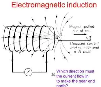
Lenz's Law, another crucial principle, explains the direction of the induced current. It states that the induced current will always flow in a direction that opposes the change in magnetic flux, acting as a stabilizing electromotive force. By combining Faraday's and Lenz's Law, we can better understand how it operates in real-world applications. For a deeper understanding of how voltage is produced in coils, explore the principles of Lenz's Law.


Core Applications: Generators and Transformers

One notable application is the electrical generator, which converts mechanical energy into electrical energy. In a typical generator, a coil of wire rotates within a magnetic field, creating a changing magnetic flux. This change induces a voltage and current in the coil, generating electricity. Generators are commonly used in power plants, automobiles, and other devices requiring a continuous electrical supply. A three-phase transformer uses electromagnetic induction to efficiently transfer power between circuits at different voltages.

Another critical application is the transformer, which transfers electrical energy between circuits with different voltages. Transformers consist of two induction coils wrapped around a shared magnetic core. When an alternating current flows through the primary coil, it creates a magnetic field that induces a voltage in the secondary coil. By adjusting the number of turns in the coils, transformers can step up or down the voltage as needed for specific electrical systems.


Special Phenomena: Eddy Currents, Mutual Inductance, and Self-Inductance

Eddy currents are an intriguing aspect of electromagnetic induction. These currents form when a magnetic field changes, causing swirling, closed loops of electric current within a conductor. Eddy currents generate heat and can lead to energy losses in electrical systems, but they also have practical applications, such as in metal detectors and induction heating. Devices that use electromagnetic induction, such as electric motors, rely on core principles of inductance to regulate energy transfer.

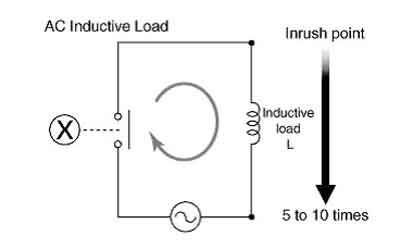
Two critical aspects of electromagnetic induction are mutual inductance and self-inductance. Mutual inductance occurs when the current in one coil induces a voltage in a nearby coil due to their shared magnetic field. Self-inductance refers to a coil's ability to induce a voltage within itself when the current flowing through it changes. Understanding these concepts is crucial for designing and analyzing complex electrical circuits and systems.


Demonstrating the Principle: Coil and Magnet Interaction

In many cases, it involves the interaction of a coil and a magnet, either a permanent magnet or an electromagnet. A bar magnet, for example, may be moved near a coil, or the coil may be moved about the magnet. This motion changes the magnetic field and induces a voltage in the coil, demonstrating the dynamic relationship between electricity and magnetism. Learning the basics of electrical resistance helps explain how eddy currents generate heat in conductive materials.


Modern Impact and Emerging Technologies

It has an immense impact on modern life, from generating electricity in power plants to operating devices like transformers, electric motors, and wireless chargers. The principles of Faraday's Law and Lenz's Law help explain the complex phenomena that occur when magnetic fields interact with conductors. By harnessing these principles, scientists and engineers have created various practical applications that have revolutionized our daily lives.

Electromagnetic induction demonstrates the fundamental relationship between electricity and magnetism and is integral to many aspects of our modern world. Faraday's Law and Lenz's Law underpin this phenomenon, governing the induced voltage and current when magnetic fields change. The applications of electromagnetic induction range from electric generators and transformers to the study of eddy currents, mutual in influence and self-inductance. By understanding these principles, we can continue to innovate and develop new technologies to improve our daily lives and advance our understanding of the world.


Induction Heating

Electromagnetic induction heating is another practical application that relies on electromagnetic induction. This technology utilizes eddy currents to heat conductive materials, such as metals. By placing a conductive material within a rapidly changing magnetic field, eddy currents are generated within the material, producing heat due to their resistance. This heating method has been employed in various industrial processes, including metal hardening, welding, and cooking.

Wireless charging is an emerging technology that utilizes electromagnetic induction to transfer energy between two coils. When an electric current flows through the primary coil, it generates a magnetic field, which induces a voltage in the secondary coil, providing power to the device. This technology has seen increasing adoption in recent years, particularly for charging electric vehicles and smartphones, offering convenience and reduced dependence on cords and cables.


Related Articles


Related News

Resistance in Series Explained

Resistance in series refers to the arrangement of individual resistors in a circuit, where the current flows through each resistor end to end. In this configuration, the total resistance (R) of the circuit is equal to the sum of the individual resistances, also known as the equivalent R.


What is Resistance in Series?

Resistance in series refers to a circuit configuration where resistors are arranged in a single path:

✅ Total resistance is the sum of all resistors in the circuit

✅ The same current flows through each resistor

✅ Voltage divides across each resistor based on its value

To calculate the total R in a series circuit, the individual resistances of each resistor are added together. The formula to calculate the equivalent resistance in a series connection is Rtotal = R1 + R2 + R3 + ..., where R1, R2, R3, and so on, represent the individual resistances of each resistor in the circuit.

Ohm's law also applies to series circuits, where the current through each resistor is the same, but the voltage across each resistor is proportional to its R. The total voltage across the series combination of resistors equals the sum of the voltage drops across each resistor.

It is essential to note that the total resistance in a series circuit is always greater than the resistance of any individual resistor in the circuit, due to the cumulative effect of each resistor's resistance.

On the other hand, resistors connected in parallel result in a parallel circuit. The equivalent R of a parallel circuit is calculated differently from a series connection. Instead of adding the individual resistances, the reciprocal of each R is added, and the resulting value is inverted to obtain the equivalent resistance.


R in Series - Parallel

When you place R-I-S, their ohmic values add up arithmetically to reach the total (or net) R.

We can connect a series of resistors (equal to the sum of the individual resistances of a parallel circuit), all having identical ohmic values, in parallel sets of series networks or series sets of parallel networks. When we do either of these things, we create a series-parallel network that can significantly increase the total power-handling capacity of the network compared to the power-handling capacity of a single parallel resistor.


Fig. 4-14. Three resistors in series. 

Sometimes, the total single equivalent R of the combination circuit in a series-parallel network equals the value of any one of the resistors. This always happens if the parallel branches or parallel combinations of the connection components are all identical and are arranged in a network called an n-by-n (or n x n) matrix. That means when n is a whole number, we have n series sets of n resistors connected in parallel, or else we have n parallel sets of n resistors connected in series in the circuit. These two arrangements yield the same practical result for electrical circuits.

A combination of series parallel combinations array of n by n resistors, all having identical ohmic values and identical power ratings, will have n2 times the power-handling capability of any resistor by itself. For example, a 3 x 3 series-parallel matrix of 2 W resistors can handle up to 32 x 2 = 9 x 2 = 18 W. If we have a 10 x 10 array of 1/2 W resistors, then it can dissipate up to 102 x 1/2 = 50 W. We multiply the power-handling capacity of each individual resistor by the total number of resistors in the matrix.

The above-described scheme works if, but only if, all of the resistors have identical ohmic values according to ohms law and identical power-dissipation ratings in terms of total voltage drops when the sum of the voltage drops across each resistor. If the resistors have values that differ even a little bit from one another, one of the components will likely draw more current than it can withstand, so that it will burn out, no matter the voltage source. Then the current distribution in the network will change further, increasing the likelihood that a second resistor will fail, and maybe more.

If you need a resistor that can handle 50 W, and a certain series-parallel connection of the network will handle 75 W, that's fine. But you should not "push your luck" and expect to get away with using a network that will handle only 48 W in the same application. You should allow some extra tolerance, say 10 per cent over the minimum rating. If you expect the network to dissipate 50W, you should build it to handle 55W or a bit more. You don't have to use "overkill," however. You'll waste resources if you cobble together a network that can handle 500W when you only expect it to cope with 50W—unless that's the only convenient combination you can make with available resistors.


Related Articles


View more

Equivalent Resistance

Equivalent resistance is the total resistance of a circuit that simplifies multiple resistors into a single resistor. It is calculated differently for series and parallel circuits, helping determine current flow, voltage distribution, and overall power consumption in electrical networks.


What is Equivalent Resistance?

Equivalent resistance is a crucial concept for individuals working with electrical circuits. It: 

✅ Represents the single resistance that replaces multiple resistors in a circuit.

✅ Simplifies calculations of current, voltage, and power.

✅ Found using series or parallel formulas based on resistor arrangement.

By mastering the calculation methods for series and parallel circuits, understanding the relationship with Ohm's law, and applying Kirchhoff's laws in more complex situations, you can efficiently analyze and design electrical systems that meet the requirements of various applications. Furthermore, by incorporating equivalent resistance calculations into your skillset, you'll be better prepared to tackle the exciting challenges presented by the ever-evolving world of electronics and power systems.


Equivalent Resistance in Series vs. Parallel Circuits

Configuration Formula Key Characteristics Example Calculation
Series R_eq = R1 + R2 + R3... Same current flows through all resistors; total resistance increases; voltage drop varies across components. For R1=4Ω, R2=6Ω: R_eq = 4Ω + 6Ω = 10Ω
Parallel 1/R_eq = 1/R1 + 1/R2 + 1/R3... Same voltage across each resistor; total resistance decreases; current divides among paths. For R1=4Ω, R2=6Ω: 1/R_eq = 1/4 + 1/6 = 0.416 → R_eq ≈ 2.4Ω

To calculate the equivalent resistance of a network, it is often necessary to determine the sum of the individual resistances. This involves adding the resistance values of each individual resistor in the network, providing a baseline for further calculations. This is a resistance formula for a single resistor, as well as for calculating resistors connected in parallel or in series.

Electrical resistance (R) is a measure of the opposition to the flow of electric current within a circuit. It is determined by the material and dimensions of the conductor, as well as the temperature and other environmental factors. It is measured in ohms (Ω), with lower R indicating greater conductivity and vice versa.


Equivalent Resistance Formula

When a group of resistors is connected end-to-end, they form a series. In a series circuit, the total resistance is equal to the sum of the individual Rs, as current must flow through each resistor in turn. The equivalent resistance of a series circuit is calculated by adding the values of each individual resistor:

Req = R1 + R2 + R3 + ...

Resistors connected across the same potential difference, or applied voltage, are referred to as being connected in parallel. In a parallel circuit, the total R is less than the R of any individual resistor as the current divides among the resistors. The equivalent resistance of a parallel circuit is calculated using the reciprocal formula:

1/Req = 1/R1 + 1/R2 + 1/R3 + ...

Equivalent resistance is the single R value that can replace a group of resistors in a circuit, offering the same overall R. This simplifies circuit analysis and allows for more straightforward calculations of current and voltage values.

Ohm's law is an essential principle in electronics and relates closely to equivalent resistance. Ohm's law states that the current (I) flowing through a resistor is directly proportional to the applied voltage (V) and inversely proportional to the R. The equation is:

V = IR

By calculating equivalent resistance for a given circuit, we can use Ohm's law to determine the overall current flowing through the circuit and the voltage drops across each resistor.


Series and parallel circuits exhibit different properties when it comes to equivalent resistance. In series circuits, the overall R increases with the addition of more resistors, which means the total current will decrease. In parallel circuits, adding more resistors results in a decrease in total resistance, causing an increase in total current. Understanding these differences is crucial for designing circuits that meet specific electrical requirements.


Kirchhoff's Law

Kirchhoff's laws are another essential tool for calculating equivalent resistance in more complex circuits that cannot be simplified as purely series or parallel. Kirchhoff's current law (KCL) states that the sum of currents entering a junction in a circuit must equal the sum of currents leaving the junction. Kirchhoff's voltage law (KVL) asserts that the sum of the voltages around any closed loop in a circuit must equal zero. By applying these laws, we can create a system of equations to solve for unknown resistance values in a network, ultimately determining the equivalent resistance.


Real-World Applications

Real-world applications of equivalent resistance can be found in various fields, such as electronics, power distribution, and telecommunications. For example, various components have different R values in electronic devices, such as smartphones. Calculating the equivalent resistance enables engineers to design efficient power management systems, ensuring optimal performance and extended battery life. In power distribution networks, equivalent resistance calculations are essential for determining voltage drops and current values across transmission lines, enabling the design of efficient and reliable power delivery systems.

Understanding equivalent resistance is vital for professionals and students who deal with electrical circuits. From simplifying complex networks to designing efficient circuits, equivalent resistance plays a central role in analyzing and developing modern electronic systems. Familiarity with this concept and associated principles like Ohm's law and Kirchhoff's laws ensures a strong foundation for anyone working with electronics, power systems, and telecommunications.


Technology Advances

As technology advances, the importance of equivalent resistance in designing and analyzing new devices and systems will only grow. Calculating and understanding equivalent resistance enables engineers to push the boundaries of innovation and improve upon existing systems, resulting in more efficient, high-performance solutions for consumers and industries alike.

To further develop your understanding of equivalent resistance and related concepts, consider exploring the wealth of educational resources available online and in textbooks, as well as seeking hands-on experience through workshops or real-world projects. Applying this knowledge to practical scenarios will enable you to tackle various electrical and electronic challenges.

Related Articles


View more

Electrical Resistance Definition Explained

Electrical resistance definition explains how materials oppose current flow in circuits, measured in ohms, linked to voltage, resistivity, conductor geometry, temperature, and impedance, governed by Ohm's law and SI units in electronics.


What Is Electrical Resistance Definition?

It is the measure of how a material opposes electric current, equal to voltage divided by current and measured in ohms.

✅ Measured in ohms; per Ohm's law, resistance R equals voltage V over current I.

✅ Depends on material resistivity, length, cross-sectional area, and temperature.

✅ Key in circuit analysis, power dissipation, signal integrity, and safety.


Electrical Resistance Definition: ER occurs in an electrical circuit when current-carrying charged particles collide with fixed particles that make up the structure of the conductors. Resistance is measured in ohm. Resistance is the ohm w. Resistance occurs in every part of a circuit, including wires and especially power transmission lines. For a concise overview, see this introduction to electrical resistance to reinforce key definitions.

Dissipation of electric energy in the form of heat affects the amount of driving voltage required to produce a given current through the circuit. In fact, volts are mesured across a circuit divided by the current I (amperes) through that circuit defines quantitatively the amount of electrical resistance R. The ohm is the common unit of electrical resistance, equivalent to one volt per ampere and represented by the capital Greek letter omega, Ω. The electrical resistance of a wire is directly proportional to its length and inversely proportional to its cross-sectional area. Resistance also depends on the material of the conductor. For instance, the resistance of a conductor generally increases with increasing temperature the resistivity. This is why some conductors have almost zero resistance when cooled to extremely low temperatures, as is the case with superconductors, because of the relative resistivity of metals. There is a temperature coefficient of resistivity. If you need a refresher on potential difference and its role in circuits, review this explanation of voltage to connect the concepts.

Alternating-current resistors for current measurement require further design consideration. For example, if the resistor is to be used for current-transformer calibration, its ac resistance must be identical with its dc resistance within 1/100th% or better, and the applied voltage difference between its voltage terminals must be in phase with the current through it within a few tenths of a minute. Thin strips or tubes of resistance material are used to limit eddy currents and minimize "skin" effect, the current circuit must be arranged to have small self-inductance, and the leads from the voltage taps to the potential terminals should be arranged so that, as nearly as possible, the mutual inductance between the voltage and current circuits opposes and cancels the effect of the self-inductance of the current circuit. In (a) a metal strip has been folded into a very narrow U; in (b) the current circuit consists of coaxial tubes soldered together at one end to terminal blocks at the other end; in (c) a straight tube is used as the current circuit, and the potential leads are snugly fitting coaxial tubes soldered to the resistor tube at the desired separation and terminating at the center. These design choices are also easier to contextualize by comparing common types of resistors used for precise AC measurements.

Electrical Resistance coils consist of insulated resistance copper wire wound on a bobbin or winding form, hard-soldered at the ends to copper terminal wires. Metal tubes are widely used as winding form for dc resistors because they dissipate heat more readily than insulating bobbins, but if the resistor is to be used in ac measurements, a ceramic winding form is greatly to be preferred because it contributes less to the phase-defect angle of the resistor. The resistance wire ordinarily is folded into a narrow loop and wound bifilar onto the form to minimize inductance. This construction results in considerable associated capacitance of high-resistance coils, for which the wire is quite long, and an alternative construction is to wind the coil inductively on a thin mica or plastic card. The capacitive effect is greatly reduced, and the inductance is still quite small if the card is thin. When specifying coil assemblies, it helps to recall the standardized unit of electrical resistance so ratings and tolerances are interpreted consistently.

Resistors in which the wire forms the warp of a woven ribbon have lower time constants than either the simple bifilar- or card-wound types. Manganin is the resistance material most generally employed, but Evanohm and similar alloys are beginning to be extensively used for very high resistance coils. Enamel or silk is used to insulate the wire, and the finished coil is ordinarily coated with shellac or varnish to protect the wire from the atmosphere. Such coatings do not completely exclude moisture, and dimensional changes of insulation with humidity will result in small resistance changes, particularly in high resistances where fine wire is used. Material behavior, moisture effects, and long term stability are discussed further in this broader overview of electrical resistance for additional context.

Electrical Resistance boxes usually have two to four decades of resistance so that with reasonable precision they cover a considerable range of resistance, adjustable in small steps. For convenience of connection, terminals of the individual resistors are brought to copper blocks or studs, which are connected into the circuit by means of plugs or of dial switches using rotary laminated brushes; clean, well-fitted plugs probably have lower resistance than dial switches but are much less convenient to use. The residual inductance of decade groups of coils due to switch wiring, and the capacitance of connected but inactive coils, will probably exceed the residuals of the coils themselves, and it is to be expected that the time constant of an assembly of coils in a decade box will be considerably greater than that of the individual coils. Understanding how series and parallel combinations set the equivalent resistance will inform how decade boxes are deployed in complex networks.

Measurement of resistance is accomplished by a variety of methods, depending on the magnitude of the resistor and the accuracy required. Over the range from a few ohms to a megohm or more, an ohmmeter may be used for an accuracy of a few percent. A simple ohmmeter may consist of a milliammeter, dry cell, and resistor in a series circuit, the instrument scale being marked in resistance units, if you obey ohm law. For a better value, the voltage drop is measured across the resistor for a measured or known current through it. Here, accuracy is limited by the instrument scales unless a potentiometer is used for the current and voltage measurements. The approach is also taken in the wide variety of digital multimeters now in common use. Their manufacturers' specifications indicate a range of accuracies from a few percent to 10 ppm (0.001%) or better from the simplest to the most precise meters. Bridge methods can have the highest accuracy, both because they are null methods in which two or more ratios can be brought to equality and because the measurements can be made by comparison with accurately known standards. For two-terminal resistors, a Wheatstone bridge can be used; for four-terminal measurements, a Kelvin bridge or a current comparator bridge can be used. Bridges for either two- or four-terminal measurements also may be based on resistive dividers. Because of their extremely high input impedance, digital voltmeters that be used with standard resistors in unbalanced bridge circuits of high accuracy. For quick reference during test planning, the fundamental resistance formula clarifies how R, V, and I are related under Ohm law.

Digital multi meters are frequently used to make low-power measurements of resistors in the range between a few ohms and a hundred megohms or so. Resolution of such instruments varies from 1% of full scale to a part per million of full scale. These meters generally use a constant-current source with a known current controlled by comparing the voltage drop on an internal "standard" resistor to the EMF produced by a Zener diode. The current is set at such a level as to make the meter direct-reading in terms of the displayed voltage; that is, the number displayed by the meter reflects the voltage drop across the resistor, but the decimal point is moved and the scale descriptor is displayed as appropriate. Multimeters typically use three or more fixed currents and several voltage ranges to produce seven or more decade ranges with the full-scale reading from 1.4 to 3.9 times the range. For example, on the 1000-0 range, full scale may be 3,999.999 Q. Power dissipated in the measured resistor generally does not exceed 30 mW and reaches that level only in the lowest ranges where resistors are usually designed to handle many times that power. The most accurate multimeters have a resolution of 1 to 10 ppm of range on all ranges above the 10-0 range. Their sensitivity, linearity, and short-term stability make it possible to compare nominally equal resistors by substitution with an uncertainty 2 to 3 times the least count of the meter. This permits their use in making very accurate measurements, up to 10 ppm, or resistors whose values are close to those of standards at hand. Many less expensive multimeters have only two leads or terminals to use to make measurements. In those cases, the leads from the meter to the resistor to be measured become part of the measured


Related Articles

View more

Voltage Drop Calculator

A voltage drop calculator helps electricians and engineers estimate line loss, wire size, and circuit efficiency. By inputting conductor length, current, and material, it ensures proper electrical design, safe voltage regulation, and compliance with power distribution standards.


What is a Voltage Drop Calculator?

A voltage drop calculator (VDC) is crucial for any electrical engineer or designer. It enables them to calculate VD accurately, which is essential for maintaining an efficient and safe electrical system.

✅ Quickly estimates voltage loss in electrical circuits

✅ Helps select the correct wire size for load and distance

✅ Supports NEC code compliance and system efficiency


Power Quality Analysis Training

Power Factor Training

Request a Free Power Quality Training Quotation

Voltage drop calculators are used in various applications, including residential, commercial, and industrial settings, and offer several benefits, such as accurate calculations, time savings, cost reduction, and hazard prevention. Additionally, engineers can ensure the electrical system operates efficiently and safely by considering factors such as cable sizing, wire gauge, and the type of conductor used. Want the full math? Visit our voltage drop formula guide for detailed equations and examples.

There are numerous VDCs available on the internet, and one of the best places to find them is on Google Play.


Applications of Voltage Drop Calculators

VDCs are used in various residential, commercial, and industrial applications. For instance, in residential applications, VDCs help determine the appropriate wire size for the electrical service panel, the length of wires, and the type of installation, ensuring that the electrical system operates correctly and safely. Additionally, VD formulas can be used to calculate resistance and reactance in both single-phase and three-phase electrical systems. It is measured in feet over a specified length.

In commercial applications, voltage drop calculators are used to design and maintain electrical systems in buildings such as hospitals, schools, and offices. These buildings require careful design to ensure that they meet the power requirements of the building and are safe for occupants. VDCs play a crucial role in this process by calculating the VD in the circuit and determining the appropriate wire size and other specifications.

In industrial applications, VDCs are used to design and maintain electrical systems in factories and other industrial settings. These systems require careful design to ensure they meet the equipment's power requirements and are safe for workers. VDCs determine the circuit's VD, the appropriate wire size, and other specifications to ensure that the electrical system operates efficiently and safely. For an overview of the general principles of voltage drop across AC and DC systems, read our article.


Benefits of Using a VDC

Using a VDC offers several benefits, including:

Accurate Calculations: VDCs use complex algorithms to calculate VD accurately. This ensures that the electrical system operates efficiently and safely.

Saves Time: VDCs save time by automating the process of calculating VD. This allows engineers to focus on other aspects of the design process, such as equipment selection and installation.

Reduces Costs: By accurately calculating VD, engineers can select the appropriate wire size and other specifications, thereby reducing the cost of the electrical system.

Prevents Hazards: Accurate calculation of VD prevents electrical hazards, including fires and shocks. 


FREE Voltage Drop Calculator 


Cable Sizing and Wire Gauge

One of the most critical factors to consider when designing an electrical system is cable sizing and wire gauge. The conductor's or wire gauge's size is critical in determining the amount of current that can flow through the conductor without causing excessive VD or overheating. American Wire Gauge (AWG) is the standard system used to specify wire sizes, providing a range of conductor sizes based on the wire's cross-sectional area. Additionally, the National Electrical Code (NEC) provides guidelines for ampacity and voltage drop (VD) for various conductor sizes and types of installations.


Copper or Aluminum Conductors

The type of conductor used in an electrical system also affects the voltage drop (VD). Copper and aluminum conductors are the most commonly used materials, with copper being preferred due to its lower resistance and higher conductivity. However, aluminum conductors are less expensive and commonly used in larger conductors and power transmission lines.


Frequently Asked Questions


How do I calculate voltage drop?

To calculate VD, you can use the VD formula, which is V = IR, where V is the voltage drop, I is the current flowing through the conductor, and R is the resistance of the conductor. By knowing the current, resistance, and length of the conductor, you can calculate the VD and determine whether it falls within acceptable limits.


How do I use it?

To use a VDC, you need to input the current flowing through the conductor, the length of the conductor, and the wire gauge or cable size. The tool then uses complex algorithms to calculate the VD in the circuit accurately. Based on the results, you can determine the appropriate wire size, cable length, and other specifications necessary to maintain an efficient and safe electrical system.


How is voltage drop calculated in a circuit?

VD is calculated in a circuit using Ohm's Law, which states that the VD across a conductor is equal to the product of the current and resistance. By knowing the current, resistance, and length of the conductor, you can calculate the VD and determine whether it falls within acceptable limits.


What factors affect voltage drop in a circuit?

The factors that affect VD in a circuit include the current flowing through the conductor, the length of the conductor, the resistance of the conductor, and the wire gauge or cable size. Other factors, such as the type of conductor and installation, can also affect VD.


Why is it important to calculate voltage drop?

Calculating VD is essential in maintaining an efficient and safe electrical system. VD can impact the performance of electrical equipment and devices, leading to hazards such as fires and electrical shock. By accurately calculating VD, engineers can select the appropriate wire size, cable length, and other necessary specifications to maintain an efficient and safe electrical system.


What are the benefits of using a VDC?

Using a VDC offers several benefits, including accurate calculations, time savings, cost reduction, and hazard prevention. By accurately calculating VD, engineers can select the appropriate wire size and other specifications, thereby reducing the cost of the electrical system. In addition, calculating VD accurately can prevent electrical hazards such as fires and shocks.


Are there any limitations to using a VDC?

While VDCs offer numerous benefits, they also have some limitations. For example, they rely on the accuracy of the input parameters, but may overlook other factors that can affect voltage drop, such as temperature and ambient conditions. Additionally, they may not be suitable for complex electrical systems.


What is the voltage drop per 100 ft?

The VD per 100 ft depends on various factors, including the current flowing through the conductor, the conductor's length, its resistance, and the wire gauge or cable size. Therefore, it is essential to calculate the VD accurately to determine the appropriate wire size and cable length necessary to maintain an efficient and safe electrical system.


What is a rule of thumb for voltage drop?

The rule of thumb for VD is that the VD in a circuit should not exceed 3% for power circuits and 5% for lighting circuits. These values are based on the National Electrical Code (NEC) guidelines, ensuring the electrical system operates efficiently and safely.

Southwire Voltage Drop Calculator


Related Pages


View more

Three Phase Electricity Explained

Three phase electricity delivers power using three alternating currents that are offset in phase. It provides consistent and efficient energy for industrial, commercial, and high-load applications, improving stability and reducing conductor size.


What is Three Phase Electricity?

Three phase electricity is a power system that uses three alternating currents, each offset by 120 degrees, to deliver constant power flow.

✅ Delivers more efficient and stable power than single-phase systems

✅ Ideal for large motors, commercial buildings, and industrial equipment

✅ Reduces conductor material and energy loss over long distances


Three phase voltage, frequency and number of wires

Three phase electricity is the dominant method of electrical power generation, transmission, and distribution across the industrialized world. Unlike single-phase systems, which rely on a single alternating current, three-phase systems use three separate currents, each 120 degrees out of phase with the others. This setup provides a consistent and balanced power flow, making it significantly more efficient for high-demand applications, such as motors, transformers, and large-scale infrastructure. Understanding the difference between alternating current and direct current is essential to grasp how three-phase systems deliver constant power using offset waveforms.


Understanding the Concept

At the heart of a three-phase system are three sinusoidal waveforms, evenly spaced to maintain a continuous flow of energy. When one phase reaches its peak, the others are in different parts of their cycle, ensuring that at any given moment, some power is being delivered. This creates what is known as constant power transfer, a major advantage over single-phase systems that experience power dips between cycles. Since three-phase systems rely heavily on accurate current flow measurement, it’s important to know what ammeters measure and how they help monitor system balance.

For industrial and commercial operations, this stability translates to increased energy efficiency, extended equipment lifespan, and reduced operating costs. Large electric motors, for example, run more smoothly on three-phase power, which avoids the surging and vibration commonly associated with single-phase inputs.


A Brief History

Three phase electricity wasn’t invented by a single person but emerged through the contributions of several pioneers in the late 19th century. Galileo Ferraris in Italy, Nikola Tesla in the United States, and Mikhail Dolivo-Dobrovolsky in Europe all played crucial roles in developing and refining the idea of three-phase alternating current. Tesla’s patents and Dolivo-Dobrovolsky’s practical systems laid the groundwork for what is now a global standard. Engineers use wattmeters to accurately measure real power in three-phase systems, while Watts Law helps calculate the relationships between voltage, current, and power.


Wye and Delta Configurations

Three-phase systems are typically wired in one of two configurations: the Wye (Y) or Delta (Δ) configuration. Each has specific advantages depending on the application:

  • In a Wye connection, each phase is tied to a central neutral point, allowing for multiple voltage levels within the same system. This is common in both commercial and residential applications, where both high and low voltages are required.

  • A Delta connection utilizes a closed loop with no neutral, a configuration commonly found in industrial setups. It delivers the same voltage between all phases and is ideal for running large motors without needing a neutral return path.

One of the most important relationships in these configurations is the √3 ratio between line voltage and phase voltage, a fundamental aspect that engineers use in calculating load, cable sizing, and protective device coordination.


Technical Benefits

Three-phase systems have built-in advantages that go beyond stability. Because the sum of the three phase currents is zero in a balanced load, a neutral wire is often unnecessary. This reduces the amount of conductor material needed, lowering costs and simplifying design. Additionally, three-phase motors naturally create a rotating magnetic field, eliminating the need for external circuitry to start or maintain rotation.

Another major benefit is that power output remains consistent. In single-phase systems, power drops to zero twice per cycle, but three-phase systems deliver non-pulsating power, which is especially important in sensitive or precision equipment. The function of a busbar is especially important in three-phase distribution panels, helping to manage multiple circuit connections efficiently.


Where and Why It’s Used

While most homes use single-phase electricity, three-phase is the standard in virtually all commercial and industrial environments. Factories, data centers, hospitals, and office buildings rely on it to power everything from HVAC systems and elevators to conveyor belts and industrial machines.

Three-phase is also common in electric vehicle (EV) charging stations and renewable energy systems, where efficient, high-capacity delivery is essential. If you're working with three-phase motors or transformers, knowing the role of a conductor and how electrical resistance affects current flow is fundamental to efficient design.

For sites that only have access to single-phase power, phase converters—whether rotary or digital—can simulate three-phase conditions, enabling them to operate three-phase equipment. This flexibility has made three-phase solutions accessible even in remote or rural areas. Three-phase systems often operate at medium voltage, especially in commercial settings, and their stability can reduce the risks of ground faults.


Voltage Levels and Color Codes

Depending on the region, the standard line and phase voltages vary. In North America, typical voltage values include 120/208 volts and 277/480 volts, whereas in Europe and much of Asia, 230/400 volts is more common. Wiring color codes also differ: red/yellow/blue in Europe, black/red/blue in North America, and other variations depending on the country's electrical code. These standards ensure safety, compatibility, and ease of troubleshooting.


The Global Standard for Power

Three-phase electricity is not just a technical solution; it is the foundation of modern electrical infrastructure. Its ability to deliver large amounts of power efficiently, safely, and reliably has made it the system of choice for more than a century. From powering the machines that build our world to the systems that keep us connected, three-phase electricity remains indispensable.


Related Articles


View more

Electricity Safety Explained

Electricity safety in electrical engineering prioritizes grounding, insulation coordination, overcurrent protection, arc-flash mitigation, lockout/tagout, and PPE to reduce shock, burn, and fire hazards in high-voltage and low-voltage installations through standards compliance and risk assessment.


What Is Electricity Safety?

Electricity safety is engineering practice to prevent shock, arc flash, and fire through design, controls, and standards.

✅ Implement grounding/earthing, bonding, and insulation coordination.

✅ Use overcurrent, residual current, and arc-fault protection.

✅ Apply NFPA 70E/IEC 60364, lockout/tagout, and arc-flash PPE.


Electricity Safety dangers involving voltages of greater than 50V are capable of producing heart fibrillation if they produce electric currents in body tissues which happen to pass through the chest area. The electrocution danger is mostly determined by the low conductivity of dry human skin. If skin is wet, or if there are wounds, or if the voltage is applied to electrodes which penetrate the skin, then even voltage sources below 40 V can be lethal if contacted. A DC circuit may be especially dangerous because it will cause muscles to lock around the wire. For a broader overview of common electrical hazards, the guide at dangers of electricity explains mechanisms of shock and injury.

Accidental contact with high voltage will usually result in severe injury or death. This can occur as a person's body provides a path for current flow causing tissue damage and heart failure. Other injuries can include burns from the arc generated by the accidental contact. These can be especially dangerous if the victims airways are affected. Injuries may also be suffered as a result of the physical forces exerted as people may fall fall from height or be thrown considerable distance. For context on regulatory and industry thresholds, see what is considered high voltage and how those limits are defined.


Electricity Safety

Depending on the short circuit current available at a switchgear line-up, a hazard is presented to maintenance and operating personnel due to the possibility of a high-intensity electric arc. Maximum temperature of an arc can exceed 10,000 kelvin, and the radiant heat, expanding hot air, and explosive vaporization of metal and insulation material can cause severe injury to unprotected workers. Such switchgear line-ups and high-energy arc sources are commonly present in electric power utility substations and generating stations and power lines, industrial plants and large commercial buildings. In the United States the National Fire Protection Association, has published a guideline standard NFPA 70E for evaluating and calculating arc flash hazard, and provides standards for the protective clothing required for electrical workers exposed to such hazards in the workplace. And even then, workers must still be careful. Understanding fault energy begins with the basics of a short circuit and how fault paths escalate incident energy.

While arc flash and arc blast are distinct, an arc fault can originate from insulation breakdown or wiring damage and quickly intensify conditions.


Explosion hazard

Even voltages insufficient to break down air can be associated with enough energy to ignite atmospheres containing flammable gases or vapours, or suspended dust. For example, air containing hydrogen gas or natural gas or gasoline vapor can be ignited by sparks produced by electrical apparatus fed by electricity lines or electricity power lines. Examples of industrial facilities with hazardous areas are petrochemical refineries, chemical plants, grain elevators, and some kinds of coal mines. In many environments, seemingly minor static electricity discharges are sufficient to ignite vapors if controls are inadequate.

Measures taken to prevent such explosions include:

  • Intrinsic safety, which is apparatus designed to not accumulate enough stored energy to touch off an explosion
  • Increased safety, which applies to devices using measures such as oil-filled enclosures to prevent contact between sparking apparatus and an explosive atmosphere
  • Explosion-proof enclosures, which are designed so that an explosion within the enclosure cannot escape and touch off the surrounding atmosphere (this designation does not imply that the apparatus will survive an internal or external explosion).

In recent years standards for explosion hazard protection have become more uniform between European and North American practice. The "zone" system of classification is now used in modified form in U.S. National Electrical Code and in the Canadian electrical code. Intrinsic safety apparatus is now approved for use in North American applications, though the explosion-proof enclosures used in North America are still uncommon in Europe. For clarity on terminology used across these standards, consult this electricity terms glossary for consistent definitions.

The Electric Safety Home is a home in which the outlet plugs, electric cords, and each electricity plug and cord plug near sinks and water sources are GFCI protected. That makes them safe. Understanding the nature of a ground fault helps explain why GFCIs trip quickly to prevent shock.


Related Articles

View more

Sign Up for Electricity Forum’s Newsletter

Stay informed with our FREE Newsletter — get the latest news, breakthrough technologies, and expert insights, delivered straight to your inbox.

Electricity Today T&D Magazine Subscribe for FREE

Stay informed with the latest T&D policies and technologies.
  • Timely insights from industry experts
  • Practical solutions T&D engineers
  • Free access to every issue

Download the 2025 Electrical Training Catalog

Explore 50+ live, expert-led electrical training courses –

  • Interactive
  • Flexible
  • CEU-cerified