Industrial Electrical Power

Arc Flash Today: Key Updates in NFPA 70E's 2024 Edition
NFPA 70E 2024 changes streamline electrical safety, arc flash risk assessment, PPE selection, lockout/tagout, and energized work permits, refining approach boundaries, incident energy analysis, labeling, and maintenance practices for compliance and worker protection.
NFPA 70E 2024 Changes Explained: What You Need to Know
NFPA 70E arc flash safety training is essential for anyone exposed to electrical hazards in the workplace. This includes electricians, electrical contractors, maintenance personnel, engineers, supervisors, safety professionals, and anyone who works with or around electrical equipment.
For those new to the topic, this introduction to NFPA 70E explains its purpose, scope, and who it protects.…
View more
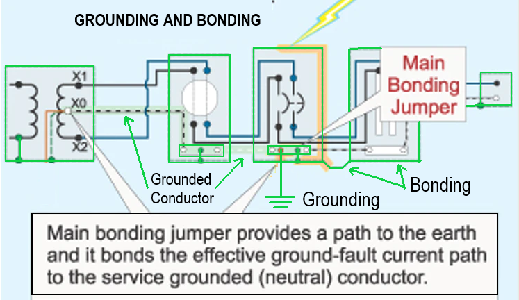
Test Your Knowledge About Grounding!
Think you know Grounding? Take our quick, interactive quiz and test your knowledge in minutes.
- Instantly see your results and score
- Identify strengths and areas for improvement
- Challenge yourself on real-world electrical topics
Latest IEP Content
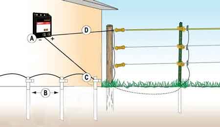
Electric Fence Ground Rod Requirements
An electric fence ground rod completes the return path through the soil, allowing fence voltage to deliver an effective shock; poor depth, spacing, or soil contact can cause weak performance even with an energizer under dry or resistive earth conditions.
Why Fence Grounding Fails Even When the Fence Is “Hot”
Electric fences operate as closed systems. The pulse leaves the energizer, travels down the fence conductor, passes through the animal, and must return through the earth to the energizer’s reference terminal. When that return path is resistive or discontinuous, voltage readings can look acceptable while delivered energy collapses under…
View more
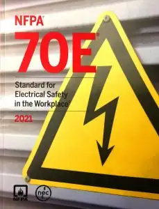
NFPA 70E-2021 - Workplace Electrical Safety
NFPA 70E 2021 defines electrical safety standards for arc flash, shock protection, PPE, risk assessment, lockout/tagout, energized work permits, boundaries, incident energy analysis, training, and OSHA-aligned compliance for industrial and commercial facilities.
Key Concepts of NFPA 70E 2021
NFPA 70E-2021 - Electrical Safety in the Workplace standard regulates the protection of electrical workers from arc flash and shock injury. For foundational context, the overview at NFPA 70E explains the scope and intent of the standard in practical terms for organizations.
The standard was developed by the National Fire Protection Association (NFPA) in 2000 for use by employers, employees, and the Occupational Safety…
View more
Understanding How to Check if an Area is Grounded
How to check if an area is grounded? Use a multimeter, receptacle tester, and visual inspection of bonding/earthing, ground rod, and service panel; verify ground resistance and continuity per NEC safety guidelines.
How to Check If an Area Is Grounded?
How to Check if an Area is Grounded: Proper grounding in any electrical system is critical for preventing electric shocks, equipment damage, and potential fire hazards. Ensuring that an area is grounded involves checking connections, testing outlets, and inspecting grounding systems to ensure they are working efficiently. In this guide, we will explore the essential steps and methods to check…
View more
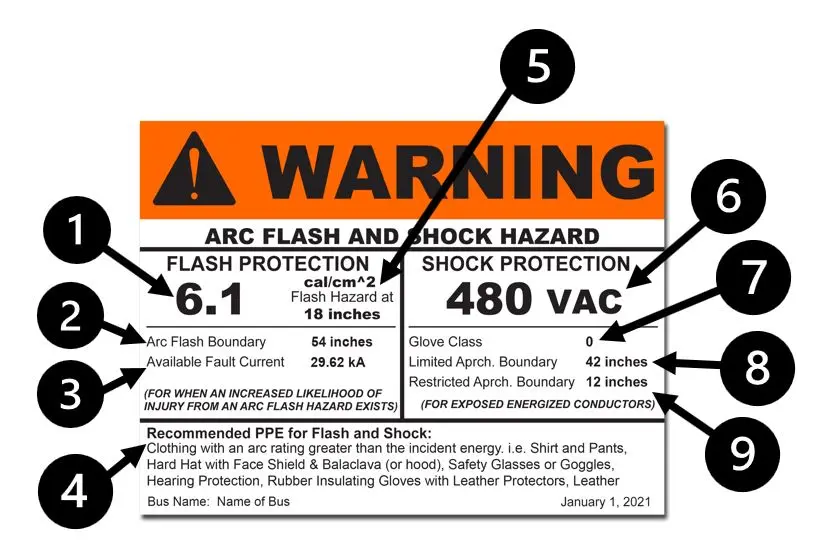
Arc Flash Rating
Arc flash rating defines PPE levels by incident energy per NFPA 70E and IEEE 1584, using ATPV in cal/cm² to guide hazard analysis, working distance, and protective clothing selection for electrical safety.
The Importance of Arc Flash Rating in Electrical Safety
Arc flash rating is a critical parameter in electrical safety, indicating the level of protection provided by personal protective equipment (PPE) against the thermal energy released during an explosive event. Understanding this is essential for selecting appropriate PPE and ensuring the safety of workers exposed to arc flash hazards. For a practical overview of garment types and selection…
View more
What is Preventive Maintenance?
What Is Preventive Maintenance? A proactive approach for electrical systems using inspections, testing, lubrication, and calibration to reduce downtime, improve reliability, extend asset life, and meet NFPA 70B/IEC standards with CMMS-driven schedules and condition monitoring.
What Is Preventive Maintenance?
Preventive maintenance is a crucial aspect of equipment management that offers numerous benefits, including improved reliability, reduced downtime, and better asset management. By implementing a well-structured maintenance plan and leveraging available tools and software, organizations can optimize their operations and ensure the long-term success of their equipment maintenance programs. To build organizational capability, teams can leverage targeted preventive maintenance training…
View more

How a Protective Relay Shapes Protection Outcomes
A protective relay sits at the center of how electrical protection decisions are made. When a fault occurs, it is not the breaker that decides whether power should be interrupted. That judgment is made upstream by the relay interpreting system, which interprets system conditions and determines whether isolation is necessary and, if so, how quickly and how selectively it should occur.
This distinction is often overlooked. Breakers interrupt current, fuses melt, and conductors carry energy, but none of those elements decides when a system has crossed from acceptable operation into a fault condition. Protective relays exist precisely to make that…
View more
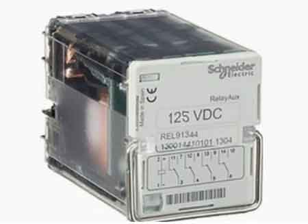
How an Auxiliary Relay Executes Protection Decisions
Auxiliary relay devices support protective relays by extending contact capacity, amplifying signals, and enabling remote control. Common in switchgear and automation, they enhance fault detection, interlocking, and the reliability of electrical protection schemes.
An auxiliary relay rarely attracts attention until something goes wrong. When a breaker fails to trip, an alarm never reaches the control room, or a protection sequence behaves unpredictably, the root cause is often not the primary protective relay but the supporting relay quietly sitting in the control circuit. These devices do not make protection decisions themselves, but they determine whether those decisions are executed cleanly, repeatedly,…
View more