Equivalent Resistance


equivalent resistance

Equivalent resistance is the total resistance of a circuit that simplifies multiple resistors into a single resistor. It is calculated differently for series and parallel circuits, helping determine current flow, voltage distribution, and overall power consumption in electrical networks.


What is Equivalent Resistance?

Equivalent resistance is a crucial concept for individuals working with electrical circuits. It: 

✅ Represents the single resistance that replaces multiple resistors in a circuit.

✅ Simplifies calculations of current, voltage, and power.

✅ Found using series or parallel formulas based on resistor arrangement.

By mastering the calculation methods for series and parallel circuits, understanding the relationship with Ohm's law, and applying Kirchhoff's laws in more complex situations, you can efficiently analyze and design electrical systems that meet the requirements of various applications. Furthermore, by incorporating equivalent resistance calculations into your skillset, you'll be better prepared to tackle the exciting challenges presented by the ever-evolving world of electronics and power systems.


Equivalent Resistance in Series vs. Parallel Circuits

Configuration Formula Key Characteristics Example Calculation
Series R_eq = R1 + R2 + R3... Same current flows through all resistors; total resistance increases; voltage drop varies across components. For R1=4Ω, R2=6Ω: R_eq = 4Ω + 6Ω = 10Ω
Parallel 1/R_eq = 1/R1 + 1/R2 + 1/R3... Same voltage across each resistor; total resistance decreases; current divides among paths. For R1=4Ω, R2=6Ω: 1/R_eq = 1/4 + 1/6 = 0.416 → R_eq ≈ 2.4Ω

To calculate the equivalent resistance of a network, it is often necessary to determine the sum of the individual resistances. This involves adding the resistance values of each individual resistor in the network, providing a baseline for further calculations. This is a resistance formula for a single resistor, as well as for calculating resistors connected in parallel or in series.

Electrical resistance (R) is a measure of the opposition to the flow of electric current within a circuit. It is determined by the material and dimensions of the conductor, as well as the temperature and other environmental factors. It is measured in ohms (Ω), with lower R indicating greater conductivity and vice versa.


Equivalent Resistance Formula

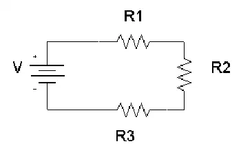
When a group of resistors is connected end-to-end, they form a series. In a series circuit, the total resistance is equal to the sum of the individual Rs, as current must flow through each resistor in turn. The equivalent resistance of a series circuit is calculated by adding the values of each individual resistor:

Req = R1 + R2 + R3 + ...

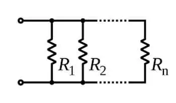
Resistors connected across the same potential difference, or applied voltage, are referred to as being connected in parallel. In a parallel circuit, the total R is less than the R of any individual resistor as the current divides among the resistors. The equivalent resistance of a parallel circuit is calculated using the reciprocal formula:

1/Req = 1/R1 + 1/R2 + 1/R3 + ...

Equivalent resistance is the single R value that can replace a group of resistors in a circuit, offering the same overall R. This simplifies circuit analysis and allows for more straightforward calculations of current and voltage values.

Ohm's law is an essential principle in electronics and relates closely to equivalent resistance. Ohm's law states that the current (I) flowing through a resistor is directly proportional to the applied voltage (V) and inversely proportional to the R. The equation is:

V = IR

By calculating equivalent resistance for a given circuit, we can use Ohm's law to determine the overall current flowing through the circuit and the voltage drops across each resistor.


Series and parallel circuits exhibit different properties when it comes to equivalent resistance. In series circuits, the overall R increases with the addition of more resistors, which means the total current will decrease. In parallel circuits, adding more resistors results in a decrease in total resistance, causing an increase in total current. Understanding these differences is crucial for designing circuits that meet specific electrical requirements.


Kirchhoff's Law

Kirchhoff's laws are another essential tool for calculating equivalent resistance in more complex circuits that cannot be simplified as purely series or parallel. Kirchhoff's current law (KCL) states that the sum of currents entering a junction in a circuit must equal the sum of currents leaving the junction. Kirchhoff's voltage law (KVL) asserts that the sum of the voltages around any closed loop in a circuit must equal zero. By applying these laws, we can create a system of equations to solve for unknown resistance values in a network, ultimately determining the equivalent resistance.


Real-World Applications

Real-world applications of equivalent resistance can be found in various fields, such as electronics, power distribution, and telecommunications. For example, various components have different R values in electronic devices, such as smartphones. Calculating the equivalent resistance enables engineers to design efficient power management systems, ensuring optimal performance and extended battery life. In power distribution networks, equivalent resistance calculations are essential for determining voltage drops and current values across transmission lines, enabling the design of efficient and reliable power delivery systems.

Understanding equivalent resistance is vital for professionals and students who deal with electrical circuits. From simplifying complex networks to designing efficient circuits, equivalent resistance plays a central role in analyzing and developing modern electronic systems. Familiarity with this concept and associated principles like Ohm's law and Kirchhoff's laws ensures a strong foundation for anyone working with electronics, power systems, and telecommunications.


Technology Advances

As technology advances, the importance of equivalent resistance in designing and analyzing new devices and systems will only grow. Calculating and understanding equivalent resistance enables engineers to push the boundaries of innovation and improve upon existing systems, resulting in more efficient, high-performance solutions for consumers and industries alike.

To further develop your understanding of equivalent resistance and related concepts, consider exploring the wealth of educational resources available online and in textbooks, as well as seeking hands-on experience through workshops or real-world projects. Applying this knowledge to practical scenarios will enable you to tackle various electrical and electronic challenges.

Related Articles


Related News

Norton's Theorem

Norton’s Theorem simplifies electrical circuit analysis by reducing any complex linear network to an equivalent current source in parallel with a resistor, enabling easier calculation of load current, evaluation of resistance, and solving practical problems.


What is Norton’s Theorem?

Norton’s Theorem states that any linear electrical network with sources and resistances can be reduced to an equivalent current source in parallel with a single resistor.

✅ Represents complex circuits as a simple current source and resistor

✅ Simplifies load current and resistance calculations

✅ Enhances circuit analysis for power systems and electronics


Understanding Norton's Theorem

Norton's Theorem is a foundational principle in electrical engineering, used to simplify the analysis of linear electronic circuits. This theorem, often taught alongside Thevenin's Theorem, provides a practical method for reducing complex circuits into a manageable form. The main insight of Norton's Theorem is that any two-terminal linear circuit, regardless of its internal complexity, can be represented by an ideal current source in parallel with a single resistor. This transformation does not alter external circuit behavior, making calculations and predictions about circuit performance far more straightforward. To fully grasp circuit simplification methods like Norton’s Theorem, it helps to start with a foundation in basic electricity.

Norton’s Theorem states that any linear electrical network can be simplified into a Norton equivalent circuit, making analysis more manageable. This representation is similar to an equivalent circuit consisting of a single current source and parallel resistance, allowing engineers to determine load behavior with ease. By calculating the total resistance of the network and combining it with the Norton current, complex problems become straightforward, enabling accurate predictions of circuit performance in both educational and real-world applications.


How Norton's Theorem Works

To use Norton's Theorem, engineers follow a step-by-step process:

  1. Identify the portion of the circuit to simplify: Usually, this means the part of the circuit as seen from a pair of terminals (often where a load is connected).

  2. Find the Norton current (IN): This is the current that would flow through a short circuit placed across the two terminals. It's calculated by removing the load resistor and finding the resulting current between the open terminals.

  3. Calculate the Norton resistance (RN): All independent voltage and current sources are deactivated (voltage sources are shorted, current sources are open-circuited), and the resistance seen from the open terminals is measured.

  4. Draw the Norton equivalent: Place the calculated current source (IN) in parallel with the calculated resistor (RN) between the terminals in question.

  5. Reconnect the load resistor: The circuit is now simplified, and analysis (such as calculating load current or voltage) is far easier.

Calculating Norton resistance often relies on principles such as Ohm’s Law and electrical resistance.


Why Use Norton's Theorem?

Complex electrical networks often contain multiple sources, resistors, and other components. Calculating the current or voltage across a particular element can be difficult without simplification. Norton's Theorem allows engineers to:

  • Save time: By reducing a circuit to source and resistance values, repeated calculations for different load conditions become much faster.

  • Enhance understanding: Seeing a circuit as a source and parallel resistor clarifies key behaviors, such as maximum power transfer.

  • Test different scenarios: Engineers can quickly swap different load values and immediately see the effect without having to recalculate the entire network each time.

Understanding how current behaves in different networks connects directly to the study of direct current and alternating current.


Comparison to Thevenin’s Theorem

Norton's Theorem is closely related to Thevenin's Theorem. Thevenin's approach uses a voltage source in series with a resistor, while Norton's uses a current source in parallel with a resistor. The two equivalents can be converted mathematically:

  • Thevenin equivalent resistance (RTH) = Norton equivalent resistance (RN)
  • Norton current (IN) = Thevenin voltage (VTH) divided by Thevenin resistance (RTH)
  • Thevenin voltage (VTH) = Norton current (IN) times resistance (RN)

Engineers applying Norton’s Theorem also draw on related concepts such as equivalent resistance and impedance to analyze circuits accurately.


Real-World Example

Suppose you need to know the current flowing through a sensor in a larger industrial power distribution board. The network supplying the sensor includes many resistors, switches, and sources. Applying Norton's Theorem, you can remove the sensor and find:

  1. The short-circuit current across its terminals (Norton current)
  2. The combined resistance left in the circuit (Norton resistance)

Once you reconnect the sensor and know its resistance, you can easily analyze how much current it will receive, or how it will affect circuit performance under different conditions.

For a deeper understanding, exploring electricity and magnetism reveals how fundamental laws, such as Faraday’s Law and Ampere’s Law, support the theory behind circuit transformations.


Applications of Norton's Theorem

  • Power system analysis: Used by utility engineers to study how changes in distribution, like maintenance or faults, impact circuit behavior.

  • Electronic device design: Common in transistors, op-amps, and other components to simplify input and output circuit analysis.

  • Fault diagnosis and protection: Helps quickly estimate fault currents for setting up protective devices in grids.

  • Education: Essential in electrical engineering curricula to develop problem-solving skills.


Limitations of Norton's Theorem

While powerful, Norton's Theorem is limited to linear circuits and cannot be directly applied to circuits with non-linear components (such as diodes or transistors in their non-linear regions). Additionally, it is only applicable between two terminals of a network; for systems with more terminals, additional techniques are required.

Norton's Theorem remains a valuable tool for engineers and students, offering clarity and efficiency in analyzing complex circuits. By transforming intricate arrangements into simple source-resistor pairs, it enables faster design iterations, troubleshooting, and optimized system performance. Whether you're analyzing a power distribution panel or designing integrated circuits, understanding and applying Norton's Theorem is an essential skill in the electrical field.


Related Articles


View more

Electrical Resistance Explained

Electrical resistance is the opposition to the flow of electric current in a material. It is measured in ohms (Ω) and depends on the conductor’s length, thickness, material, and temperature.


What is Electrical Resistance?

Electrical resistance is a fundamental concept in engineering that defines how much a material opposes the flow of electric current. Measured in ohms (Ω), resistance (Ω) plays a crucial role in circuit design, power distribution, and electronic applications.

✅ Measured in ohms (Ω) and calculated using Ohm’s Law

✅ Influenced by material, length, area, and temperature

✅ Key factor in circuit safety, design, and energy loss


Think of electricity moving like water through a pipe. If the pipe is narrow or obstructed, less water flows through it. Similarly, in a wire or conductor, certain materials make it harder for electrons to move freely. This obstruction results in energy loss, often seen as heat.

The ease or difficulty of electric charge movement depends on the conductivity of a material. Metals like copper allow current to flow easily, while rubber or glass inhibit it entirely. This behavior plays a key role in how systems are designed and protected. Discover how resistors are used in circuits to manage voltage and protect components by providing controlled resistance.


Electrical Resistance – Example Values by Material/Component

Material/Component Approx. Resistance Notes
Copper wire (1 meter, 1mm²) ~0.017 ohms Very low resistance, ideal for conductors
Aluminum wire (1m, 1mm²) ~0.028 ohms Higher resistance than copper
Iron wire (1m, 1mm²) ~0.10 ohms Often used in heating elements
Nichrome wire (1m, 1mm²) ~1.10 ohms High-resistance alloy used in toasters and heaters
Human body (dry skin) 1,000–100,000 ohms Varies greatly with moisture and contact
Incandescent light bulb ~240 ohms (cold) Resistance increases when hot
Resistor (carbon film) Fixed (e.g., 220 ohms) Used to control current in circuits
Air (dry) ~1 trillion ohms (insulator) Excellent natural insulator unless ionized
Superconductor 0 ohms Only at extremely low temperatures (near absolute zero)


Electrical Resistance Definition

Several factors affecting electrical resistance include the type of material, temperature, and the dimensions of the conductor. When an electric charge moves through a material, its ease of flow depends on the material’s conductivity. A high-conductivity material allows charges to move more freely, resulting in lower resistance. The resistance of a conductor increases with its length and decreases with its cross-sectional area. Therefore, the resistance of a wire is directly related to both its physical properties and the material from which it is made. The resistance of a conductor depends heavily on its length and cross-sectional area, as outlined in our resistance formula breakdown.

This opposing property is quantified using Ohm’s Law:

R = V / I

Where:

  • R is the resistive value in ohms

  • V is voltage (volts)

  • I is current (amperes)

Another useful expression involves material properties:

R = ρ × (L / A)

Where:

  • ρ is resistivity (material-specific)

  • L is length

  • A is cross-sectional area

These formulas show that the longer or thinner the conductor, the harder it is for current to move through it.


Unit of Electrical Resistance – The Ohm (Ω)

The ohm is the SI unit of resistance, named after German physicist Georg Ohm. One ohm is defined as the resistance between two points of a conductor when a potential difference of one volt causes a current of one ampere to flow.

Common multiples:

  • kΩ (kilo-ohm) = 1,000 ohms

  • MΩ (mega-ohm) = 1,000,000 ohms

Resistance can be measured using a multimeter, and is especially important in designing and troubleshooting power  and electronic circuits. To understand how voltage and resistance interact in a circuit, see our guide on Ohm’s Law.


Ohm’s Law and Circuit Function

Ohm’s Law helps us understand how voltage, current, and resistance relate. For example:

  • Increase the resistive load, and current drops.

  • Increase voltage with fixed resistance, and current rises.

These principles help control energy flow, prevent overloads, and design efficient systems.


Measuring and Expressing Opposition

The ohm (Ω) is the standard unit used to quantify this phenomenon. One ohm means that a current of one ampere flows when one volt is applied. Components with fixed values, like resistors, are labelled accordingly—e.g., 100 Ω, 1 kΩ, or 1 MΩ.

To measure the current-limiting capacity of a material, a digital multimeter is used. It applies a small voltage and calculates the resulting current flow to determine the opposition level. If you're working with different wire types, explore the unit of electrical resistance for conversion insights and resistance ranges.


Real-World Examples of Resistance

  • Heating Elements: Toasters, ovens, and electric heaters utilize high-resistance materials, such as nichrome wire.

  • Power Transmission: Long-distance wires are designed with low resistance to reduce energy loss as heat.

  • Electronic Components: Resistors regulate current in circuits, protecting components from overload.

For real-world scenarios involving current flow, our article on voltage drop explains how resistance affects electrical efficiency over distance.


Factors Affecting Electrical Resistance

  • The resistance of a conductor depends on:

    • Material – copper vs. aluminum vs. nichrome

    • Length – longer wires restrict current more

    • Thickness – wider wires allow easier flow

    • Temperature – many materials resist current more when heated

    Thus, the resistance of a wire can vary dramatically depending on where and how it’s used. Materials with high conductivity (like silver or copper) allow electrons to move with minimal restriction, whereas poor conductors like rubber greatly hinder charge movement.


Superconductors – Zero Resistance?

In some materials, when cooled to extremely low temperatures, resistance drops to zero. These superconductors enable electricity to flow without energy loss, but their use is limited to specialized fields, such as MRI machines or experimental power lines, due to cost and cooling requirements.


Frequently Asked Questions


What causes electrical resistance?

It results from collisions between electrons and atoms in a conductor, which convert energy into heat.


What is the formula for calculating it?

 R = V/I or R = ρ × (L / A)


How is it measured?

With a multimeter in ohms (Ω), using a small test voltage and measuring current. Learn how instruments like a digital multimeter are used to measure opposition to current flow in electrical systems.


Why is this concept important?

It controls current flow, prevents damage, and enables functions like heating or dimming.


Can resistance ever be zero?

Yes—in superconductors under specific extreme conditions.

Electrical resistance is a foundational concept in understanding how electricity behaves in materials and systems. From household wiring to high-voltage power lines and sensitive electronics, it plays a crucial role in determining safety, efficiency, and performance. For a broader view on electric flow and material response, read about electrical conductivity and current electricity.


Related Articles


View more

Static Electricity

Static electricity is a fascinating phenomenon that can be both awe-inspiring and dangerous. Understanding its basic concepts, including the movement of charged particles and the causes of positive and negative charge imbalance, is crucial in preventing potential hazards. By taking preventive measures such as grounding equipment and surfaces, using anti-static materials, and increasing humidity, we can avoid the buildup of static charges and protect ourselves and our environment from its hazards. It is also important to understand the potential dangers and take appropriate precautions, particularly when working with flammable or explosive materials. With this knowledge, we can safely harness the power and explore its many fascinating properties.


What is static electricity?

It results from the movement of charged particles, called electrons and particles called protons, which make up the atoms of matter. Atoms are made up of protons, neutrons, and electrons. Protons have a positive charge, electrons have a negative charge, and neutrons have no charge. In most atoms, the positive charge of the protons is balanced by the negative charge of the electrons, resulting in a neutral object.

However, when two objects come in contact, the extra electrons from one object may transfer to the other, creating a charge imbalance. This results in one object having a positive charge and the other having a negative electric charge. These charges repel, and when the objects are separated, they retain the charges, creating a static charge.


What causes static electricity?

As previously mentioned, it is caused by the movement of charged particles. When there is a charge imbalance between two objects, it can create a static charge. This can occur through friction, conduction, or induction.

Friction occurs when two objects rub against each other, causing electrons to transfer from one object to the other. For example, this is why you may experience it when you rub a balloon against your hair, causing your hair stand to stand up.

Conduction occurs when two objects come in contact and transfer electrons between them. For example, when you touch a doorknob, you may receive a static shock if the doorknob is charged.

Induction occurs when a charged object is brought near a neutral object, causing a charge to be induced in the neutral object.


How does static electricity work?

It creates a charge imbalance between two objects, resulting in one object having a positive charge and the other having a negative charge. These charges repel each other, and when the objects are separated, they retain the charges, creating a static charge.

When a charged object comes in contact with a neutral object, the charge may transfer, resulting in a static shock. This occurs when the charge imbalance is released as a spark. Static shocks are usually harmless but can sometimes be dangerous, particularly in hazardous environments.


Can static electricity hurt you?

While it is usually harmless, it can sometimes be dangerous. A static shock occurs when a charged object comes in contact with a person or object that is not charged. The shock results from the charge imbalance being released as a spark. The shock can be uncomfortable, and in rare cases, it can cause serious injury, mainly if it occurs in a hazardous environment, such as around flammable materials.


What are the dangers of static electricity?

It can be dangerous in certain situations, such as when working with flammable or explosive materials. A spark from it can ignite flammable gases or vapours, leading to fires or explosions. In industrial settings, it is important to take precautions to prevent the buildup of static charges and to discharge any charges that may occur.


How do you discharge static electricity?

There are several ways to discharge it, including:

  • Grounding: Connecting the charged object to a ground source such as the earth, which dissipates the excess charge.
  • Anti-static materials: Wearing clothes made of anti-static materials or using anti-static sprays can prevent the buildup of static charges.
  • Humidification: Increasing the humidity in a room can help reduce a buildup by adding moisture to the air.
  • Use of ionizers: Ionizers can neutralize it by releasing negative ions into the air.
  • Proper grounding of equipment: Ensuring that all equipment and surfaces are properly grounded can prevent the buildup of static charges.


How can you prevent static electricity?

Preventing buildup involves taking several steps, such as:

  • Using anti-static materials: Clothing made of anti-static materials or anti-static sprays can prevent the buildup of static charges.
  • Grounding: Ensuring that all equipment and surfaces are properly grounded can prevent the buildup of static charges.
  • Humidification: Increasing the humidity in a room can help reduce a buildup by adding moisture to the air.
  • Proper handling of flammable materials: When working with flammable or explosive materials, it is important to take proper precautions to prevent a buildup and discharge of any charges.
  • Using equipment designed for use in hazardous environments: Equipment designed for use in hazardous environments is designed to prevent a buildup and sparks from occurring.

In addition to these preventive measures, it is important to understand the basics of static electricity and the factors that contribute to its buildup. This knowledge can help individuals take steps to avoid buildup and prevent any potential hazards.


Van de Graaff Generator: An Experiment with Static Electricity

One fascinating example of this is the Van de Graaff generator. This device was invented in 1929 by Robert J. Van de Graaff and is used to generate high voltages of static electricity. The generator transfers electrons from a moving belt to a metal sphere, creating a charge imbalance between the two objects.

This charge imbalance creates a strong electric field, which can be used to demonstrate various phenomena. For example, the electric field can cause hairs on a person's head or arm to stand up due to the repulsion between the positively charged hair and the positively charged metal sphere.


View more

Understanding Ground Electricity

Ground electricity underpins grounding and earthing practices, managing earth potential and fault current. It ensures equipotential bonding, surge protection, and safety compliance per IEC/NEC standards for power systems, electronics, and lightning protection.


What Is Ground Electricity?

Ground electricity is the earth reference and return path that stabilizes systems and safely carries fault current.

✅ Provides low-impedance fault current paths to trip protection

✅ Uses earth electrodes, bonding, and grounding conductors

✅ Reduces touch voltage, EMI, and lightning surge damage


Understanding Ground Electricity 

Ground Electricity is a general term that is often used loosely to refer to “Bonding” (Safety Grounding) and “Earth Grounding”.  Personnel of major industries have often misinterpreted grounding to mean that anything in contact with the earth is considered to be grounded. For foundational context, see our overview on how electricity works to understand why grounding concepts are sometimes conflated.

Electrical Grounding is the reference zero for the electrical system.  When we talk about 120 Volts RMS, it represents 120 units above the zero electrical reference.  In residential settings, this reference is commonly tied to service equipment, as explained in our guide to home electricity and typical distribution practices.

Electrical Grounding is the reference zero for the electrical system and all the equipment should be at this same equipment potential plane. Maintaining that equipotential plane is central to electricity safety because it minimizes touch voltage hazards.

According to accident reports, most electrical accidents occur when the earth is used as the safety grounding system (Bonding).   These incidents underscore the broader dangers of electricity when protective paths are improperly designed.

Accident reports details the hazards of using earth as a safety grounding and the practice of electrical grounding the equipment through local grounds. (grounding each individual piece of equipment with a separate ground rod, driven into the earth).  Improper local grounds can also complicate fault clearing during a system electrical fault, increasing damage and downtime.

The best method for ensuring the safety of personnel is to use a “Bonding Conductor”. This conductor should be continuous, with sufficient ampacity and the lowest impedance path back to the circuit interrupting devices, which insures positive operation of the protective devices. A robust bonding network ensures rapid clearing of a ground fault by providing a low-impedance return path for protective devices.

Once a system that connects all the metallic frames of electrical equipment together has been established, then the grounding system must be placed at “Zero Reference Potential”.  The earth grounding electrode should have the lowest resistance value possible, preferably 5 ohms or less.   Coordinating equipment bonding with proper transformer grounding helps maintain stable reference potential across the installation.

This low resistance to earth ground electricity will limit the potential of the electrical system to earth (limiting the stresses placed on components such as switches, insulators and transformers).

It will also reduce the effects of static charges on the electrical system and will protect against lightning strokes, lightning induced voltages, and minimizes the effects of transient over-voltages.

Visit Our Electrical Grounding and Bonding Course 


Related Articles

View more

Understanding Current

Current is the flow of electric charge in circuits, defined by amperage, driven by voltage, limited by resistance, described by Ohm’s law, and fundamental to AC/DC power systems, loads, conductors, and electronic components.


What Is Current?

Current is charge flow in a circuit, measured in amperes and governed by voltage and resistance.

✅ Measured in amperes; sensed with ammeters and shunts

✅ Defined by Ohm’s law: I = V/R in linear resistive circuits

✅ AC alternates; DC is steady; sets power transfer P = V*I


Current is best described as a flow of charge or that the charge is moving. Electrons in motion make up an electric current. This electric current is usually referred to as “current” or “current flow,” no matter how many electrons are moving. Current is a measurement of a rate at which a charge flows through some region of space or a conductor. The moving charges are the free electrons found in conductors, such as copper, silver, aluminum, and gold. The term “free electron” describes a condition in some atoms where the outer electrons are loosely bound to their parent atom. These loosely bound electrons can be easily motivated to move in a given direction when an external source, such as a battery, is applied to the circuit. These electrons are attracted to the positive terminal of the battery, while the negative terminal is the source of the electrons. The greater amount of charge moving through the conductor in a given amount of time translates into a current. For a concise overview of how moving charges create practical circuits, see this guide to current electricity for additional context.


The System International unit for current is the Ampere (A), where


That is, 1 ampere (A) of current is equivalent to 1 coulomb (C) of charge passing through a conductor in 1 second(s). One coulomb of charge equals 6.28 billion billion electrons. The symbol used to indicate current in formulas or on schematics is the capital letter “I.” To explore the formal definition, standards, and measurement practices, consult this explanation of the ampere for deeper detail.

When current flow is one direction, it is called direct current (DC). Later in the text, we will discuss the form of current that periodically oscillates back and forth within the circuit. The present discussion will only be concerned with the use of direct current. If you are working with batteries or electronic devices, you will encounter direct current (DC) in most basic circuits.

The velocity of the charge is actually an average velocity and is called drift velocity. To understand the idea of drift velocity, think of a conductor in which the charge carriers are free electrons. These electrons are always in a state of random motion similar to that of gas molecules. When a voltage is applied across the conductor, an electromotive force creates an electric field within the conductor and a current is established. The electrons do not move in a straight direction but undergo repeated collisions with other nearby atoms. These collisions usually knock other free electrons from their atoms, and these electrons move on toward the positive end of the conductor with an average velocity called the drift velocity, which is relatively a slow speed. To understand the nearly instantaneous speed of the effect of the current, it is helpful to visualize a long tube filled with steel balls as shown in Figure 10-37. It can be seen that a ball introduced in one end of the tube, which represents the conductor, will immediately cause a ball to be emitted at the opposite end of the tube. Thus, electric current can be viewed as instantaneous, even though it is the result of a relatively slow drift of electrons. For foundational concepts that connect drift velocity with circuit behavior, review this basic electricity primer to reinforce the fundamentals.

Current is also a physical quantity that can be measured and expressed numerically in amperes. Electric current can be compared to the flow of water in a pipe. It is measureda at the rate in which a charge flows past a certain point on a circuit. Current in a circuit can be measured if the quantity of charge "Q" passing through a cross section of a wire in a time "t" (time) can be measured. The current is simply the ratio of the quantity of charge and time. Understanding current and charge flow also clarifies how circuits deliver electrical energy to perform useful work.


Electrical current is essentially an electric charge in motion. It can take either the form of a sudden discharge of static electricity, such as a lightning bolt or a spark between your finger and a ground light switch plate. More commonly, though, when we speak of current, we mean the more controlled form of electricity from generators, batteries, solar cells or fuel cells.  A helpful overview of static, current, and related phenomena is available in this summary of electricity types for quick reference.

We can think of the flow of electrons in a wire as the flow of water in a pipe, except in this case, the pipe of water is always full. If the valve on the pipe is opened at one end to let water into the pipe, one doesn't have to wait for that water to make its way all the way to the other end of the pipe. We get water out the other end almost instantaneously because the incoming water pushes the water that's already in the pipe toward the end. This is what happens in the case of electrical current in a wire. The conduction electrons are already present in the wire; we just need to start pushing electrons in one end, and they start flowing at the other end instantly. In household power systems, that push on conduction electrons alternates in direction as alternating current (AC) drives the flow with a time-varying voltage.


Current Formula

Current is rate of flow of negatively-charged particles, called electrons, through a predetermined cross-sectional area in a conductor.

 Essentially, flow of electrons in an electric circuit leads to the establishment of current.

q = relatively charged electrons (C)

t = Time

Amp = C/sec

Often measured in milliamps, mA


Related Articles

View more

Alternative Electricity Key To Carbon Reduction

Alternative electricity integrates renewable energy, smart grids, and distributed generation, combining solar photovoltaics, wind power, hydropower, and battery storage with power electronics and demand response to decarbonize grids and improve reliability.


What Is Alternative Electricity?

Alternative electricity uses renewables, storage, and smart grids to deliver reliable, low-carbon power.

✅ Power electronics enable PV, wind, and storage grid integration

✅ Smart inverters support voltage, frequency, and reactive power control

✅ Microgrids improve resilience with islanding and load management


Alternative electricity power is essential if we are to find affordable and workable sources of energy before the world completely consumes its limited supply of energy sources. Many countries have started to introduce renewable energy schemes and many countries have invested money into researching and even producing different sources of electricity energy. While it is essential that we become less reliant or not reliant at all on fossil fuels, many forms of alternate energy have their disadvantages as well as their obvious advantages. The advantages of alternate energy far outweigh the disadvantages. For a primer on how modern grids convert primary energy into usable power, see this overview of how electricity is generated across different technologies today.


Wind Energy

Harnessing the power of the wind and using it to our ends is hardly a new idea. Windmills have been and still are used for many different purposes and have been for a great many years, but the improvement of turbines combined with the improved technology to turn the motion of turbine blades into an energy source has seen a marked increase in the use of electricity generating turbines. Detailed diagrams explain how turbine blades capture kinetic energy to generate electricity efficiently under varying wind speeds.

Wind power is very popular, but in order to provide a reasonable amount of power it may prove necessary to have large amounts of turbines. On windy days, and even not so windy days some turbines make a noise that many residents consider to be unbearable. Areas of open countryside are protected by conservation orders, which means they can’t be built there either and if there is no conservation order there are still protestors willing to do almost anything to stop the turbines being built. The only viable option left is to use offshore wind farms and these are being investigated, developed and planned all around the world but it takes too many turbines to create a reasonable amount of power and eventually they will have to be built inland; a matter that will be contested wherever the wind farms are proposed to be built.

Understanding capacity factors and grid integration is key to planning electricity production that balances reliability and community impacts.

Wind power is produced by converting wind energy into electricity. Electricity generation from wind has increased significantly in the United States since 1970. Wind power provided almost 5% of U.S. electricity generation in 2015. These trends mirror broader shifts in electricity generation portfolios as states pursue renewable portfolio standards.


Solar Energy

Solar energy is probably the most common form of alternate energy for everyday people and you can see solar lights ad other solar accessories in many gardens. Governments are beginning to offer grants to assist in paying for photovoltaic roof tiles; these tiles are easily fitted onto your roof and collect the heat from the sun. This heat can either be used to heat water or can even be converted into energy electric power. The advantage for the consumer is that by including a grid tie system you can actually sell unused energy back to the grid. Photovoltaic tiles take the place of ordinary roof tiles and can be perfectly blended to fit the look of the outside of your house. With solar energy you too can help the environment.

Many utilities now offer tariffs that credit exports from rooftop systems, linking household budgets to green electricity choices in a transparent way.

Solar power is derived from energy from the sun. Photovoltaic (PV) and solar-thermal electric are the two main types of technologies used to convert solar energy to electricity. PV conversion produces electricity directly from sunlight in a photovoltaic (solar) cell. Solar-thermal electric generators concentrate solar energy to heat a fluid and produce steam to drive turbines. In 2015, nearly 1% of U.S. electricity generation came from solar power. PV and solar-thermal now sit alongside other major sources of electricity in utility planning models.


Biomass

Ask most people which renewable energy source is the most widely used and they would say either wind or solar, but they’d be wrong or at least they certainly would in America. Since 2000 Biomass has been the most highly produced alternate energy in the United States. Using plant and animal material to create energy isn’t without its downfalls. It would almost certainly meet with competition from residents if biomass power stations were to be created in built up areas. The decomposing plants and animal waste creates an awful smell that is incredibly difficult to mask but it is very renewable (there’s always plants and animal waste).

Biomass is material derived from plants or animals and includes lumber and paper mill wastes, food scraps, grass, leaves, paper, and wood in municipal solid waste (garbage). Biomass is also derived from forestry and agricultural residues such as wood chips, corn cobs, and wheat straw. These materials can be burned directly in steam-electric power plants, or they can be converted to a gas that can be burned in steam generators, gas turbines, or internal combustion engine-generators. Biomass accounted for about 2% of the electricity generated in the United States in 2015.


Other renewable energy sources

These are the main three renewable energy sources that the countries of the world are creating at the moment but there are others. Whether nuclear power is a viable alternate or not is a debate that will undoubtedly rage on forever, but it is a renewable energy and some countries already have extensive capabilities to produce it. Modern technology means that nuclear power stations are safer than they’ve ever been and damage to people, animals or plantation is highly unlikely. However, it takes a long time to develop nuclear power station and even plants that are already being built may take ten years to come to fruition.


Renewable energy sources provide 13% of U.S. electricity

Hydropower, the source of about 6% of U.S. electricity generation in 2015, is a process in which flowing water is used to spin a turbine connected to a generator. Most hydropower is produced at large facilities built by the federal government, like the Grand Coulee Dam. The West has many of the largest hydroelectric dams, but there are many hydropower facilities operating all around the country. For a deeper look at how turbines and dams convert flow into water electricity, engineers often study case histories from multiple river systems.

Hydro power is used in some countries and uses the motion of waves to create energy. While it is a possibility, the amount of energy produced is minimal and the outlay to set these schemes up is quite large. Without further investigation and improvement in the techniques used it is unlikely that Hydropower will become a major player in the renewable energy world.

Geothermal power comes from heat energy buried beneath the surface of the earth. In some areas of the United States, enough heat rises close enough to the surface of the earth to heat underground water into steam, which can be tapped for use at steam-turbine plants. Geothermal power generated less than 1% of the electricity in the United States in 2015.


Related Articles

View more

Sign Up for Electricity Forum’s Newsletter

Stay informed with our FREE Newsletter — get the latest news, breakthrough technologies, and expert insights, delivered straight to your inbox.

Electricity Today T&D Magazine Subscribe for FREE

Stay informed with the latest T&D policies and technologies.
  • Timely insights from industry experts
  • Practical solutions T&D engineers
  • Free access to every issue

Live Online & In-person Group Training

Advantages To Instructor-Led Training – Instructor-Led Course, Customized Training, Multiple Locations, Economical, CEU Credits, Course Discounts.

Request For Quotation

Whether you would prefer Live Online or In-Person instruction, our electrical training courses can be tailored to meet your company's specific requirements and delivered to your employees in one location or at various locations.