Electrical Energy
By R. W. Hurst, Editor
Electrical energy is the total amount of energy transferred or delivered by electricity over time, calculated as power multiplied by time. It is defined by the relationship E = P × t, where energy depends on how much power is used and for how long it operates. Electrical energy is measured in joules (J) and more commonly in watt-hours (Wh) or kilowatt-hours (kWh), and is used to quantify electricity generation, consumption, and energy use in circuits, systems, and utility billing.
Unlike electrical power, which describes the rate at which energy is delivered at a specific moment, electrical energy represents the total amount delivered over a period of time. Power indicates how fast electricity is being used, while energy indicates how much electricity has actually been transferred during operation.
Electrical energy is applied throughout the electrical system. It is produced by generators, transported through transmission and distribution networks, stored in batteries and other energy storage systems, and converted by loads into light, heat, motion, or other useful forms. This makes electrical energy a fundamental quantity for describing how electricity is created, moved, and used.
Electrical Energy Formula
Electrical energy in a circuit can be calculated using relationships between power, voltage, current, and time. The most common expression is:
E = P × t
where electrical energy equals electrical power multiplied by the time of operation.
Because electrical power is defined as:
P = V × I
electrical energy can also be written as:
E = V × I × t
Electrical energy may be expressed in joules (J), but in power systems it is more commonly measured in watt-hours (Wh) or kilowatt-hours (kWh), which reflect practical energy consumption and delivery.
Electrical energy is closely related to how power is delivered in systems such as Electricity Power, where the rate of energy transfer determines system performance.
Electrical Energy Example Calculation
A 100-watt light bulb operating for 3 hours consumes:
E = P × t
E = 100 W × 3 h
E = 300 Wh
This means the lamp uses 300 watt-hours of electrical energy during that period. In utility systems, energy use is typically measured in kilowatt-hours (kWh), the standard unit for billing and energy tracking.
To understand how electrical energy moves through circuits, it is essential to understand Voltage, which provides the potential difference that drives energy transfer.
Electrical energy transfer depends on the flow of charge, which is defined by Current and its movement through conductors.
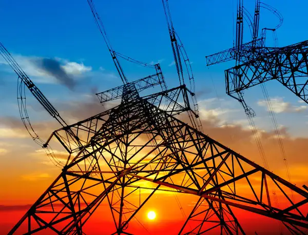
Electrical Energy in Power Systems
In power systems, electrical energy refers to the transfer of energy as electric charge moves under the influence of voltage. It can be generated from mechanical, thermal, chemical, or renewable sources and delivered over long distances through transmission and distribution networks.
Once generated, electrical energy is transmitted and managed through interconnected networks described in Electric Power Systems.
Electrical energy is generated at scale through processes described in Electricity Generation, where mechanical or thermal energy is converted into electrical energy.
Once delivered to a load, electrical energy is converted into other forms depending on the application. Lighting systems convert it into visible light, heating systems into thermal energy, motors into mechanical motion, and electronic devices into signals and processing functions.
To see how electrical energy is produced, transmitted, and used in real systems, refer to How Electricity Works.
Electrical energy is best understood as a transfer quantity rather than something stored in a conductor. The energy moves through the system as electric fields drive charge through circuits, enabling near-instantaneous response across electrical networks.
Electrical Energy and Voltage
Voltage represents the electrical potential difference between two points and determines how much energy is available to move charge through a circuit. Electrical energy depends directly on this potential difference, as higher voltage corresponds to more energy available per unit of charge.
Without voltage, current does not flow and no electrical energy is transferred. For this reason, voltage levels are carefully controlled across generation, transmission, and utilization systems to ensure efficient energy delivery.
The relationship between voltage, current, and resistance is defined by What Is Ohm's Law, which governs how electrical energy behaves in circuits.
Electrical Energy and Current
Electric current is the flow of electric charge through a conductor and is measured in amperes. Electrical energy transfer occurs when current flows under the influence of a voltage, allowing energy to move through circuits from the source to the load.
The rate of current flow, combined with voltage, determines electrical power, and over time, this results in the total electrical energy delivered. In this way, current is a key component in how electrical energy is transferred and utilized in practical systems.
Related Articles

