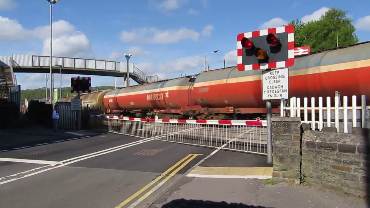
Around the world, railway tracks pass through villages, towns, cities and metropolises which creates the problem of ubiquitous Level Crossings as they transect roads, highways, etc. The real-time train data, collected through Global Positioning System (GPS) satellites can be used to calculate critical distance to a level crossing. A sensor (receiver) keeps polling the approaching train data and actuates a motor that closes the gate of an unmanned LC.
Case Study – Indian Railways and problems with its LCs
Since the past few years, Indian Railways (IR) has been making strides in the realm of digital technology. Being the largest employer in the world, means managing a mammoth workforce and movement of passengers every day, equal to the population of Australia. Unfortunately, this includes running trains and transporting goods on a stagnated infrastructure of railroads. Both manned and unmanned Level Crossings, cause several accidents. The manned LCs, that have an operator, to pull the gate, are unreliable and often lead to delays for public, that wants to get from one side of the railway track to another.
Solution - Data from satellites
Taking advantages of advancements made in the field of satellite communications technology, Indian Railways has started using Global Positioning System data for running its trains. It collects the actual data as received from the satellites and links it to mobile phone applications and its web portal where travelers can find the running status of a train, they are interested in. This gives any user, information, such as speed, last station passed, time to reach the selected destination (approx.) and whether if the train is running late or at the right time.
Building Blocks of the proposed system – PLC and its FBD
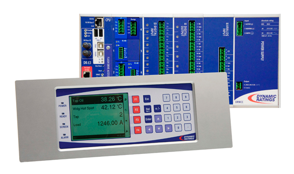
A Programmable Logic Controller, or PLC, Fig. 1, is like a mini computer used for industrial automation everywhere around us. These controllers can automate a specific process, machine function, or even an entire production line. They can be made to calculate positions and take actions based on the status. The PLC receives information from connected sensors or input devices (thru the Input Modules), processes the data (in its Processor), and triggers outputs (connected to the Output Module) based on pre-programmed parameters. Depending on the inputs and outputs, a PLC can monitor and record run-time data, automatically start and stop processes, generate alarms if a machine malfunctions, and more. Programmable Logic Controllers are a flexible and robust control solution, adaptable to almost any application.
Fig. 1 - A Programmable Logic Controller consisting of a Power Supply, CPU and input and output modules.
Modern PLCs are programmed using Functional Block Diagram (FBD). They were introduced by IEC 61131-3 to overcome the weaknesses associated with textual programming and ladder diagrams. An FBD network, Fig. 2, primarily comprises interconnected functions and function blocks to express system behavior. Function blocks were introduced to address the need to reuse common tasks such as AND gate, OR gate, counters, and timers at different parts of an application or in different projects. A function block is a packaged element of software that describes the behavior of data, a data structure and an external interface defined as a set of input and output parameters. A function block is depicted as a rectangular block with inputs entering from the left and outputs exiting on the right. Key features of function blocks are data preservation between executions, encapsulation, and information hiding.
An FBD is a program constructed by connecting multiple functions and function blocks resulting in one block that becomes the input for the next. Unlike textual programming, no variables are necessary to pass data from one subroutine to another because the wires connecting different blocks automatically encapsulate and transfer data.
A function block is not evaluated unless all inputs that come from other elements are available. When a function block executes, it evaluates all its variables, including input and internal variables as well as output variables. During its execution, the algorithm creates new values for the output and internal variables. Outputs of function blocks are updated because of function block evaluations. Changes of signal states and values therefore naturally propagate from left to right across the FBD network.
Fig. 2 - Functional Block Diagram (FBD) used to program a PLC. Complex mathematic operations are performed by simple functions in steps, deriving outputs from one or multiple inputs.
Automated LCs
The GPS data collected from satellites can be used for supplementary applications using simple systems integration technologies to improve a city’s infrastructure.
The LC has a sensor (receiver) which keeps polling the approaching train data continuously from the satellites. The receiver sends this information to a Programmable Logic Controller, which calculates the "critical distance to the crossing" (difference, based on coordinates) The FBD can be designed using a comparator that compares real time position input to a pre-set value (say 300 ft.). It shall then proceed to calculate the difference of these 2 values. If this value is zero, then the output should become 1, which means that the train is now in the crossing envelope and the gates need to be shut. This output feeds the motor starting circuit. An important thing to note here are the factors influencing this calculation such as, the speed of the train and its distance away from the crossing envelope. Another parameter affecting this calculation is the width of the road, across the railway track. For wider roads, crossing envelope is more, on both sides of the road, which leads to the crossing envelope’s pre-set value to be more (than 300 ft.). While for narrow roads the crossing envelope pre-set value can be set to a lesser margin (less than 300 ft).
Making use of the several digital outputs available at the output module of the PLC, extra functionalities that can be added to the PLC circuit may include a horn sound, to alert the public near the crossing and a stop (RED) or go (GREEN) light. The power supply for this system is derived from Uninterruptible Power Supply (UPS) system with a battery unit, See Fig. 3.
Fig. 3 – GPS based Automated Level Crossing for Railroads
As the train, approaches the crossing, the gate will be closed, stopping the traffic on the road, until the train has moved away from the crossing envelope on the other side of the road.
When the train has gone out of the critical distance, using real time polling from GPS, the PLC will run its FBD again. The FBD will now not have a zero output but a positive value as the difference of the pre-set value (300 ft. in our example) and the current coordinates of the train is a positive number. After running this sequence for 2 minutes, and finding a positive number in the output of the FBD, it can open the gate by reversing the motor. This restores movement of road traffic.
Have more data? Use it for automation
The PLC can be programmed to detect and transmit alarms for faults in cases such as when the Motor does not start or the Battery units are low on the charge and need replacement. During such situations, PLC can send this information thru a wireless signal to the nearest control center, Fig.3. A Rail Infrastructure Operations & Maintenance (O&M) app or website could collect all this data and send out maintenance personnel to look after the equipment periodically thereby enhancing the life of the LC unit. A Central Control Operator (CCO) screen, Fig. 4, can display erroneous behavior of any equipment. The development of interface between the PLC and CCO requires detailed engineering and sound knowledge of communications.
Fig. 4 – A sample Central Control operator screen shows the health of all the equipment. It is very important to keep monitoring the real-time status of critical infrastructure so necessary action can be taken subsequently.
Advantages aplenty
Railway Operators have a responsibility towards everyone, from the travelers on the trains and stations to people using its infrastructure elsewhere. Automated LCs will prevent accidents. This system is faster, as often guards at LC tend to shut the gates 10 to 15 minutes before the approach of the train, causing loss of valuable time of the public. Being a satellite based system, it is bound to be very precise and accurate. It will also save money as the need for guards to be present at such crossings will be eliminated.
Way forward
As various Railway Operators around the globe, look for ways to keep themselves functional and profitable, all railway crossings should be converted to automatic type, removing the need for a guard to be present 24x7. This solution can be a lynchpin to a digital revolution. Within a city’s limits, such automated LCs will enable transition towards a smart city and smart transport initiatives. Railway Operators must realize the importance of the data that they generate and put it to several innovative uses that makes people’s life easy.
Kshitij Saxena received his BTech in electrical and electronics engineering from Vellore Institute of Technology (2008) and MS in electrical engineering from University of Southern California (2010).
He is currently working as a Senior Traction Power Engineer at WSP Oakland, USA. Previously he has worked with Bombardier Transportation and Pennsylvania Transformer Tech Inc.
Mr. Saxena is an Engineer in Training from Pennsylvania and is a PMP. He’s passionate about Mass Transit & Renewable Energy.


_1547716275.jpg)