What is a Conductor?
By R.W. Hurst, Editor
A conductor is a material that allows electric current to flow easily because it has low electrical resistance. In electrical systems, this behavior occurs because conductors contain free electrons that move when voltage is applied, creating a controlled path for current through wires, cables, and circuit components.
Electrical conductors are essential for power distribution, signal transmission, and equipment operation. Without conductors, electricity could not be delivered, controlled, or used in practical applications. Copper and aluminum are the most common conductor materials because they combine high conductivity, durability, and cost efficiency.
A conductor is defined by how freely it permits electron movement, not by its shape or size. This property distinguishes conductors from insulators, which restrict electron flow and prevent current from passing through.
Electrical conductors operate within complete circuits, which are explained in detail in our guide to what is an electrical circuit and how current paths are formed.
What is a Conductor?
Understanding what a conductor is and how it functions is crucial to comprehending various aspects of modern life, including electricity, thermal management, and electronics. Conductors facilitate the flow of electrons and heat in various applications, while insulators impede these movements. Due to their unique properties and availability, copper, silver, and aluminum are good electrical conductors. As a result, they are among the most commonly used conductor materials because they facilitate the flow of electricity. Factors affecting conductivity include atomic structure, temperature, and material purity.
The movement of free electrons inside a conductor is governed by the same principles described in Ohm’s law, which defines the relationship between voltage, current, and resistance.
Conductors are an integral part of our daily lives, enabling the functioning of various devices and systems we depend on, such as electrical wiring and electronic devices. In contrast, thermal conductors facilitate heat transfer in numerous applications, from car engines to cookware. In addition, the unique category of semiconductors demonstrates that a material can possess both conductive and insulating properties, paving the way for the development of advanced technologies such as transistors and solar cells.
The Role of Conductors in Electricity
A conductor plays an essential role in the world of electricity. It enables the movement of electrons within a material, allowing electrical charge to flow smoothly through an electrical circuit. Electrical conductors consist of atoms that have loosely bound electrons, which are free to move and generate a current when an electric field is applied. This phenomenon underlies the flow of electrons in many electrical devices and systems.
Conductors behave differently in alternating current and direct current systems because of changes in the direction of electron flow.
Conductors and Insulators: The Key Differences
The primary difference between conductors and insulators lies in their ability to conduct electricity. While conductors, which are solid in nature, allow the flow of electrons, insulators impede this flow because their electrons are tightly bound. Consequently, insulators prevent electric shock or maintain electrical charge within specific boundaries. Good insulators include rubber, plastic, and glass.
Safety risks increase when conductors are damaged or exposed, as described in our overview of the dangers of electricity.
Common Conductor Materials
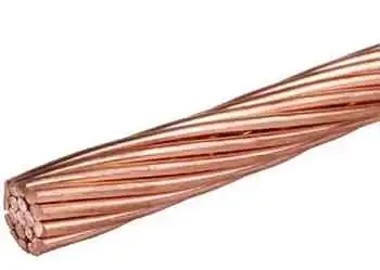
The most commonly used electrical conductors are copper, silver, and aluminum. Copper conductors are often preferred due to their excellent conductivity, relatively low cost, and high availability. Silver possesses the highest conductivity but is more expensive and less abundant. Aluminum is lightweight and affordable, making it an attractive choice for various applications such as power lines.
In power systems, conductor performance directly affects voltage stability, as discussed further in our article on voltage drop.
Factors Affecting Conductivity
The conductivity of a material depends on several factors, including its atomic structure, temperature, and purity. Materials with more free electrons or a regular atomic arrangement are more conducive. Temperature can also influence conductivity, as higher temperatures may cause the atoms in a material to vibrate more, leading to increased resistance. Purity is another essential factor, as impurities can impede electron flow, reducing conductivity.
Applications of Conductors in Everyday Life
Conductors play a vital role in our daily lives, providing the foundation for many devices and systems that rely on the movement of electrons. Some notable examples include electrical wiring, power lines, and electronic devices such as computers and smartphones. Additionally, conductors are used in protective gear, such as fire-resistant clothing, which incorporates metal fibres to dissipate heat from the body. Conductors are essential components in energy transfer within modern electric power systems.
Thermal Conductors: Function and Use
Thermal conductors allow heat to flow through them, effectively conducting heat from one area to another. This process is essential in many applications, such as in car engines, where conductors help dissipate heat away from the engine to prevent overheating. Thermal conductors are also found in household items, such as pots and pans, where heat must be transferred evenly for efficient cooking.
Can a Material be Both a Conductor and an Insulator?
In some cases, the material can exhibit both conductive and insulating properties. These materials are semiconductors, which have a conductivity level between that of conductors and insulators. Silicon and germanium are two common examples of semiconductors. Semiconductors have numerous applications in electronic devices, including transistors and solar cells, which can regulate electrical current and convert sunlight into electricity.

As our understanding of conductors and their properties expands, we anticipate further innovations and improvements in the materials used in these essential components. For example, new conductor materials and composites could potentially be developed, offering better performance, higher efficiency, or enhanced durability. These advancements will contribute to the creation of even more sophisticated technologies and further enhance the quality of our everyday lives.
Related Articles

