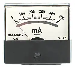
What is a Voltmeter?
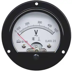

What is a Voltmeter

What is a voltmeter? A voltmeter is an electrical measuring instrument used to determine voltage across circuit points. Common in electronics, engineering, and power systems, it ensures accuracy, safety, and efficiency when monitoring current and diagnosing electrical performance.


What is a Voltmeter?

A Voltmeter provides a method to accurately measure voltage, which is the difference in electric potential between two points in a circuit, without changing the voltage in that circuit. It is an instrument used for measuring voltage drop.

✅ Ensures accurate voltage measurement for safety and performance

✅ Used in electrical engineering, electronics, and power systems

✅ Helps diagnose faults and maintain efficient operation

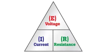
Electrical current consists of a flow of charge carriers. Voltage, also known as electromotive force (EMF) or potential difference, manifests as "electrical pressure" that enables current to flow. Given an electric circuit under test with a constant resistance, the current through the circuit varies directly in proportion to the voltage across the circuit. A voltmeter measures potential difference, which directly relates to Ohm’s Law, the fundamental equation connecting voltage, current, and resistance in circuits.

A voltmeter can take many forms, from the classic analog voltmeter with a moving needle to modern instruments like the digital voltmeter (DVM) or the versatile digital multimeter. These tools are essential for measuring electrical values in electronic devices, enabling technicians to measure voltage, current, and resistance with precision and accuracy. While analog units provide quick visual feedback, digital versions deliver more precise measurements across wider voltage ranges, making them indispensable for troubleshooting and maintaining today’s complex electrical systems.

A voltmeter can be tailored to have various full-scale ranges by switching different values of resistance in series with the microammeter, as shown in Fig. 3-6. A voltmeter exhibits high internal resistance because the resistors have large ohmic values. The greater the supply voltage, the larger the internal resistance of the voltmeter because the necessary series resistance increases as the voltage increases. To understand how a voltmeter works, it helps to first review basic electricity, as voltage, current, and resistance form the foundation of all electrical measurements.


Fig 3-6. A simple circuit using a microammeter (tA) to measure DC voltage.


A Voltmeter, whether digital or analog, should have high resistance, and the higher the better. You don't want the meter to draw a lot of current from the power source. (Ideally, it wouldn't draw any current at all.) The power-supply current should go, as much as possible, towards operating whatever circuit or system you want to use, not into getting a meter to tell you the voltage. A voltmeter is commonly used to measure voltage drop across conductors or devices, helping electricians ensure circuits operate efficiently and safely. For quick calculations, a voltage drop calculator provides accurate estimates of conductor losses based on length, size, and current. Understanding the voltage drop formula allows engineers and technicians to apply theoretical principles when designing or troubleshooting electrical systems.

Also, you might not want to keep the voltmeter constantly connected in parallel in the circuit. You may need the voltmeter for testing various circuits. You don't want the behavior of a circuit to be affected the moment you connect or disconnect the voltmeter. The less current a voltmeter draws, the less it affects the behavior of anything that operates from the power supply. Engineers often ask: What is a voltmeter?  They use a voltmeter in power system analysis, where accurate voltage readings are crucial for ensuring safety, reliability, and optimal performance.

Alternative types of voltmeters use electrostatic deflection, rather than electromagnetic deflection, to produce their readings. Remember that electric fields produce forces, just as magnetic fields do. Therefore, a pair of electrically charged plates attracts or repels each other. An electrostatic type utilizes the attractive force between two plates with opposite electric charges or a large potential difference. A voltmeter is used to measure the potential difference. Figure 3-7 portrays the functional mechanics of an electrostatic meter. It constitutes, in effect, a sensitive, calibrated electroscope. A voltmeter draws essentially no current from the power supply. Nothing but air exists between the plates, and air constitutes a nearly perfect electrical insulator. A properly designed electrostatic meter can measure both AC voltage and DC voltage. However, the meter construction tends to be fragile, and mechanical vibration can influence the reading.


Fig 3-7. Functional drawing of an electrostatic voltmeter movement.


It's always good when a voltmeter has a high internal resistance. The reason for this is that you don't want the voltmeter to draw a significant amount of current from the power source. This cur­rent should go, as much as possible, towards working whatever circuit is hooked up to the supply, and not just into getting a reading of the voltage. Additionally, you may not want or need to have the voltmeter constantly connected in the circuit; instead, you might need it for testing various circuits. You don't want the behavior of the circuit to be affected the instant you connect the voltmeter to the supply. The less current a voltmeter draws, the less it will affect the behavior of anything that is working from the power supply.

If you connect an ammeter directly across a source of voltage, a battery, the meter needle will deflect. In fact, a milliammeter needle will probably be "pinned" if you do this with it, and a microammeter might well be wrecked by the force of the needle striking the pin at the top of the scale. For this reason, you should never connect milli-ammeters or micro-ammeters directly across voltage sources. An ammeter, perhaps with a range of 0-10 A, may not deflect to full scale if it is placed across a battery; however, it's still a bad idea to do so, as it will rapidly drain the battery. Some batteries, such as automotive lead-acid cells, can explode under these conditions. This is because all ammeters have low internal resistance. They are designed that way deliberately. They are meant to be connected in series with other parts of a circuit, not right across the power supply. Because voltage is inseparable from current, learning what is current electricity provides deeper insight into why voltmeters are vital diagnostic tools.

But if you place a large resistor in series with an ammeter, and then connect the ammeter across a battery or other type of power supply, you no longer have a short cir­cuit. The ammeter will give an indication that is directly proportional to the voltage of the supply. The smaller the full-scale reading of the ammeter, the larger the resistance needed to get a meaningful indication on the meter. Using a microammeter and a very large resistor in series, it can be devised that draws only a small current from the source.

So, What is a Voltmeter? In summary, a voltmeter is a fundamental instrument for electrical work, allowing professionals and students to accurately measure voltage and understand circuit behaviour. Whether using an analog or digital design, voltmeters and multimeters provide precise insights that support safety, efficiency, and reliable performance in electrical systems.

Related Articles


Related News

What is Impedance? Explained

Impedance is the total opposition a cable or circuit offers to alternating current (AC). It combines resistance and reactance, measured in ohms (Ω), and determines how easily AC signals move through a circuit, affecting voltage, current, and power.


What is Impedance?

Impedance refers to the opposition that an electrical circuit presents to the flow of alternating current. It is a complex quantity that combines resistance and reactance, shaping how signals behave in AC systems.

✅ Combines resistance and reactance in AC circuits

✅ Measured in ohms and affects signal flow and power

✅ Essential in analyzing voltage, current, and circuit behavior


Understanding impedance (Z) is essential for anyone working with AC circuits. It influences how electrical energy flows, how efficiently components interact, and how systems handle varying frequencies. To understand how impedance interacts with voltage, explore our explanation of what is voltage and how it affects current flow in electrical circuits.

Electrical resistance is the opposition to direct current, while reactance opposes alternating current. Reactance arises from capacitors and inductors: capacitive reactance decreases with frequency, while inductive reactance increases. Together, these elements define the circuit’s impedance and its effect on current, voltage, and power transfer.

Impedance is crucial in AC circuit analysis because it enables engineers and technicians to calculate how voltage and current behave. This understanding facilitates efficient design, troubleshooting, and energy transfer, particularly when impedance matching is necessary for optimal performance. In AC systems, the behavior of inductors is described by inductance, which directly contributes to the reactive part of impedance.


Impedance Formula and Complex Representation

Impedance is defined mathematically by the formula:

Z = V / I

Where:

  • Z is impedance in ohms (Ω)

  • V is voltage (volts)

  • I is current (amperes)

This relationship is a natural extension of Ohm’s Law, which defines the link between voltage, current, and resistance in DC circuits. In AC analysis, impedance expands this concept by including reactance and phase angle.

In AC systems, impedance is expressed as a complex impedance:

Z = R + jX

Where:

  • R is resistance (real part)

  • X is reactance (imaginary part)

  • j is the imaginary unit

This representation accounts for both magnitude and phase angle, enabling the modelling of the interaction between voltage and current in AC circuits. Capacitors also play a key role, and understanding capacitance is essential to see how impedance decreases at higher frequencies.


Frequency, Phase Angle, and Reactance

Impedance depends on frequency. As frequency increases, reactance (especially inductive and capacitive) also changes, which shifts the phase angle between voltage and current.

  • Inductive reactance (XL = 2πfL) increases with frequency

  • Capacitive reactance (XC = 1 / 2πfC) decreases with frequency

As a result, the total impedance can change significantly depending on the signal. Engineers must consider this when analyzing harmonics or designing high-frequency systems. Learn how resistance contributes to impedance by reviewing what is electrical resistance and how it differs from reactance in AC systems.


Common Applications of Impedance

Understanding impedance is critical in many areas of electrical and electronic engineering:

  • Audio Systems: Proper impedance matching ensures maximum power transfer and sound clarity between amplifiers and speakers.

  • Radio Frequency (RF): Antenna design and transmission lines rely on precise impedance matching to minimize signal loss.

  • RLC Circuits: Impedance analysis enables tuning and resonance calculations in resistor-inductor-capacitor (RLC) networks.

  • Power Systems: Impedance affects fault current calculations, load flow, and harmonic analysis.

  • Phasor Analysis: Engineers use phasors to represent voltage and current in the frequency domain, relying on impedance to model AC behavior. For insights into the capacitive elements of impedance, see what is a capacitor and how it stores energy in electric fields.


Power System Impedance (Advanced)

At fundamental frequency, power systems are mostly inductive, and the equivalent impedance is often described as short-circuit reactance. While capacitive effects are typically minor in utility and industrial systems, they become significant in harmonic analysis. Short-circuit impedance, often derived from system studies, is a critical factor in these calculations.


Short-Circuit Reactance

If phase data is unavailable, engineers usually assume impedance is purely reactive—a reasonable approximation in many cases. However, transformer and line resistance may need to be considered for accurate harmonic modeling. The inductive reactance portion of impedance scales linearly with frequency, and engineers must carefully apply this when analyzing short-circuit conditions.


Transformer Resistance Effects

Resistance in transformers and conductors can change with frequency due to skin effect or eddy current losses. Large substation transformers, for example, may exhibit resistance that increases almost in proportion to frequency, which can help dampen resonance. In smaller transformers, winding resistance dominates and remains nearly constant until higher frequencies are reached. At utilization voltages, such as in industrial power systems, the service transformer’s impedance often accounts for more than 90% of total system impedance.

Transformer impedance in ohms can be estimated from the nameplate percentage impedance:

Z (Ω) = (Z% / 100) × (V² / kVA)

For instance, a 1,500 kVA transformer with a 6% impedance at 480 V has an equivalent impedance of approximately 9.22 Ω. This simplification is often sufficient to evaluate harmonic resonance risks and system behavior. For more on efficiency, review what the power factor is and its impact on AC systems.


Harmonic Considerations

One common mistake in harmonic analysis is neglecting to adjust reactance for frequency. The reactance at the h-th harmonic is determined from the fundamental reactance X1 by:

where h is the harmonic number and X1 is the fundamental reactance magnitude. (For capacitive branches specifically: XC,h = XC,1 / h, while inductive branches scale as XL,h = h × XL,1.)

In many power systems, resistance remains nearly unchanged up to the ninth harmonic. However, at higher frequencies, skin effect increases conductor resistance, and transformer eddy current losses further influence apparent resistance. These factors affect resonance conditions and can alter predictions of harmonic distortion.

Neglecting resistance generally yields a conservative, higher prediction of distortion. But when transformer effects dominate system behavior, resistance should be modeled more carefully. Impedance matching is especially important in such cases for ensuring stability and avoiding resonance issues in AC power systems. The impact of impedance extends to system-level issues like harmonic distortion, which can affect stability and power quality if not managed correctly.


Calculating Total Impedance

The total impedance (Z_total) of a circuit depends on how elements are connected:

Series circuits:

Z_total = √ (R_total² + (X_L – X_C)²)

Parallel circuits:

Z_total = 1 / (1/Z₁ + 1/Z₂ + …)

These calculations follow the same principles as Ohm’s Law, but are adapted for AC circuits where both resistance and reactance determine the current flow. By combining these components, engineers can predict circuit response, design filters, and ensure efficient energy transfer. Calculating impedance is a crucial part of power system analysis, where accurate models enable the prediction of current flow, voltage stability, and fault levels.


Impedance Matching and Spectroscopy

Impedance matching adjusts the source and load to the same impedance, maximizing power transfer and minimizing reflections. It is essential in audio systems, RF communications, and transmission line design.

Impedance spectroscopy extends the concept further, analyzing a material or device across a range of frequencies. This method reveals electrical properties such as conductivity, dielectric response, and electrochemical behavior, guiding the design of advanced materials and devices.


Conclusion

Impedance is a cornerstone of AC circuit analysis, uniting resistance and reactance into a single complex value that varies with frequency. From audio clarity to power system stability, impedance shapes how electricity flows and interacts in real-world systems. By mastering impedance—whether matching speaker loads, modeling harmonic resonance, or studying material properties—engineers and technicians can design more efficient, reliable, and safe electrical systems.


Related Articles


View more

What is a Resistor?

A resistor is an electronic component that limits or regulates the flow of electric current, manages voltage levels, and safeguards circuits in electrical and electronic devices, ensuring stable performance and preventing component damage.


What is a resistor?

A resistor is an electronic component designed to create electrical resistance in a circuit.

✅ Limits or regulates electric current flow in circuits

✅ Controls voltage levels for proper device operation

✅ Protects electrical and electronic components from damage

In electronic components and circuits, resistors play a crucial role. But what exactly is a resistor, and why are they so important? This comprehensive guide will explain the basics of resistors, explore different types and applications, and answer common questions related to their function and use. 

Their primary function is to control and limit the flow of electrical current, ensuring the proper operation of electronic devices and, in addition, introducing resistance to help maintain stable voltage and current levels in circuits, protecting sensitive components from damage due to excess current.


Electrical Resistance

Understanding electrical resistance is essential to grasping how resistors control current flow and protect sensitive components in circuits. The value of a resistor is determined by its electrical resistance, which is measured in ohms (Ω). Resistance is directly related to Ohm's law, a fundamental principle in electronics that states that the current (I) flowing through a conductor between two points is directly proportional to the voltage (V) across those points and inversely proportional to the resistance (R). In simpler terms, the equation V = I represents Ohm's law of R. Resistors work alongside capacitors and other components to regulate voltage and ensure stable performance in electronic devices. The unit of electrical resistance, the ohm (Ω), defines how much a resistor opposes the flow of electric current.

Various types of resistors are available, each with its own set of applications and characteristics. Some common resistor types include fixed resistors, variable resistors, carbon film resistors, metal foil resistors, metal oxide film resistors, and wire-wound resistors.

As the name suggests, fixed resistors have a fixed resistance value and are often used for general-purpose applications. Carbon film and metal film resistors are popular examples of fixed resistors, with the latter offering higher accuracy and stability. On the other hand, wire-wound resistors are constructed using a metal wire wrapped around a core, providing excellent heat dissipation and making them suitable for high-power applications.


Types of Resistors

Variable resistors, also known as potentiometers or rheostats, allow users to adjust the resistance manually. These components are typically used for fine-tuning and controlling various aspects of electronic circuits, such as volume or light intensity. Different types of resistors offer unique properties for specific applications, from precision electronics to high-power systems.

Resistor colour codes identify the value, tolerance, and sometimes the temperature coefficient of fixed resistors. The colour code consists of a series of coloured bands, with each colour representing a specific number. To read the colour code, you need to learn the number assigned to each colour and understand the sequence of bands.

The primary difference between fixed and variable resistors is the ability to adjust the resistance value. Fixed resistors have a predetermined resistance that cannot be changed, while variable resistors can be adjusted to obtain the desired resistance within a certain range.


Power Dissipation

Power dissipation is the heat a resistor generates when electrical current flows through it. This heat can affect the performance and reliability of a resistor and, in some cases, may cause damage to the component or the circuit. To prevent such issues, resistors are designed with a power rating, which indicates the maximum amount of power they can safely dissipate.

A resistor is integral to electronic circuits and can be found in virtually every electronic device. They come in various shapes, sizes, and materials to suit various applications. With their ability to control electrical current and maintain the stability of circuits, resistors play a vital role in the successful operation of electronic devices.


What is a resistor?

Resistors are essential electronic components that help regulate electrical current and voltage within circuits. Their various types and applications cater to different needs in the electronics world. Understanding resistors and their characteristics is crucial for anyone working with electronic circuits or looking to build their own devices.


Related Articles


View more

What is Voltage?

Voltage is the electrical potential difference between two points, providing the force that moves current through conductors. It expresses energy per charge, powering devices, controlling circuits, and ensuring efficient and safe operation of electrical and electronic systems.


What is Voltage?

Voltage is the electric potential difference, the work done per unit charge (Joules per Coulomb). It: 

✅ Is the difference in electric potential energy between two points in a circuit.

✅ Represents the force that pushes electric current through conductors.

✅ It is measured in volts (V), and it is essential for power distribution and electrical safety.

To comprehend the concept of what is voltage, it is essential to understand its fundamental principles. Analogies make this invisible force easier to picture. One of the most common is the water pressure analogy: just as higher water pressure pushes water through pipes more forcefully, higher voltage pushes electric charges through a circuit. A strong grasp of voltage begins with the fundamentals of electricity fundamentals, which explain how current, resistance, and power interact in circuits.

Another way to imagine what is voltage is as a hill of potential energy. A ball placed at the top of a hill naturally rolls downward under gravity. The steeper the hill, the more energy is available to move the ball. Likewise, a higher voltage means more energy is available per charge to move electrons in a circuit.

A third analogy is the pump in a water system. A pump creates pressure, forcing water to move through pipes. Similarly, a battery or generator functions as an electrical pump, supplying the energy that drives electrons through conductors. Without this push, charges would remain in place and no current would flow.

Together, these analogies—water pressure, potential energy hill, and pump—show how voltage acts as the essential driving force, the “electrical pressure” that enables circuits to function and devices to operate. Since voltage and Current are inseparable, Ohm’s Law shows how resistance influences the flow of electricity in every system.

These analogies help us visualize voltage as pressure or stored energy, but in physics, voltage has a precise definition. It is the work done per unit charge to move an electric charge from one point to another. Mathematically, this is expressed as:

V = W / q

where V is voltage (in volts), W is the work or energy (in joules), and q is the charge (in coulombs). This equation shows that one volt equals one joule of energy per coulomb of charge.

In circuit analysis, voltage is also described through Ohm’s Law, which relates it to current and resistance:

V = I × R

where I is current (in amperes) and R is resistance (in ohms). This simple but powerful formula explains how voltage, current, and resistance interact in every electrical system.

Italian physicist Alessandro Volta played a crucial role in discovering and understanding V. The unit of voltage, the volt (V), is named in his honor. V is measured in volts, and the process of measuring V typically involves a device called a voltmeter. In an electrical circuit, the V difference between two points determines the energy required to move a charge, specifically one coulomb of charge, between those points. The history of voltage is closely tied to the History of Electricity, where discoveries by pioneers like Volta and Franklin have shaped modern science.

An electric potential difference between two points produces an electric field, represented by electric lines of flux (Fig. 1). There is always a pole that is relatively positive, with fewer electrons, and one that is relatively negative, with more electrons. The positive pole does not necessarily have a deficiency of electrons compared with neutral objects, and the negative pole might not have a surplus of electrons compared with neutral objects. But there's always a difference in charge between the two poles. So the negative pole always has more electrons than the positive pole.


Fig 1. Electric lines of flux always exist near poles of electric charge.


The abbreviation for voltage measurement is V. Sometimes, smaller units are used. For example, the millivolt (mV) is equal to a thousandth (0.001) of a volt. The microvolt (uV) is equal to a millionth (0.000001) of a volt. And it is sometimes necessary to use units much larger than one volt. For example, one kilovolt (kV) is equal to one thousand volts (1,000). One megavolt (MV) is equal to one million volts (1,000,000) or one thousand kilovolts. When comparing supply types, the distinction between Direct Current and AC vs DC shows why standardized voltage systems are essential worldwide.

The concept of what is voltage is closely related to electromotive force (EMF), which is the energy source that drives electrons to flow through a circuit. A chemical battery is a common example of a voltage source that generates EMF. The negatively charged electrons in the battery are compelled to move toward the positive terminal, creating an electric current.

In power distribution, three-phase electricity and 3 Phase Power demonstrate how higher voltages improve efficiency and reliability.

Voltage is a fundamental concept in electrical and electronic systems, as it influences the behavior of circuits and devices. One of the most important relationships involving V is Ohm's Law, which describes the connection between voltage, current, and resistance in an electrical circuit. For example, Ohm's Law states that the V across a resistor is equal to the product of the current flowing through it and the resistance of the resistor. 

The voltage dropped across components in a circuit is critical when designing or analyzing electrical systems. Voltage drop occurs when the circuit components, such as resistors, capacitors, and inductors, partially consume the V source's energy. This phenomenon is a crucial aspect of circuit analysis, as it helps determine a system's power distribution and efficiency. Potential energy is defined as the work required to move a unit of charge from different points in an electric dc circuit in a static electric field.  Engineers often analyze Voltage Drop to evaluate circuit performance, alongside concepts like Electrical Resistance.

Voltage levels are standardized in both household and industrial applications to ensure the safe and efficient operation of electrical equipment. In residential settings, common voltage levels range from 110 to 240 volts, depending on the country. Industrial applications often utilize higher voltages, ranging from several kilovolts to tens of kilovolts, to transmit electrical energy over long distances with minimal losses.

Another important distinction in the realm of voltage is the difference between alternating current (AC) and direct current (DC). AC alternates periodically, whereas DC maintains a constant direction. AC is the standard for most household and industrial applications, as it can be easily transformed to different voltage levels and is more efficient for long-distance transmission. DC voltage, on the other hand, is often used in batteries and electronic devices.

Voltage is the driving force behind the flow of charge carriers in electrical circuits. It is essential for understanding the behavior of circuits and the relationship between voltage, current, and resistance, as described by Ohm's Law. The importance of V levels in household and industrial applications, as well as the significance of voltage drop in circuit analysis, cannot be overstated. Finally, the distinction between AC and DC voltage is critical for the safe and efficient operation of electrical systems in various contexts.

By incorporating these concepts into our understanding of voltage, we gain valuable insight into the world of electricity and electronics. From the pioneering work of Alessandro Volta to the modern applications of voltage in our daily lives, it is clear that voltage will continue to play a crucial role in the development and advancement of technology. Foundational principles such as Amperes Law and the Biot Savart Law complement voltage by describing how currents and magnetic fields interact.


Related Articles


View more

Types of Capacitors

The types of capacitors vary by design and application, including ceramic, electrolytic, film, and supercapacitors. Each offers unique benefits for electronics, power supply circuits, energy storage, and filtering needs.


What are the types of capacitors?

The types of capacitors are classified by material, function, and performance, serving vital roles in electronics and electrical systems.

✅ Ceramic, electrolytic, film, and supercapacitors used in diverse applications

✅ Store and regulate electrical energy in circuits, power systems, and devices

✅ Enable filtering, smoothing, and energy storage for stable performance


There are various types of capacitors. They are electronic components of electric filters and tuned circuits that store and release electrical energy. They consist of two conductive plates separated by a dielectric material. When a voltage is applied across the plates, an electric field is created between them, and an electrical charge accumulates on the plates. It represents the distance between the plates. The capacitance of a polarized capacitor is a measure of its ability to store electrical charge. To fully understand how capacitance works in different circuits, it is essential to study the various types and their dielectric materials.

These are widely used in electronic circuits, performing various functions such as filtering, smoothing, coupling, and timing. They can be found in everything from simple electronic devices like flashlights and radios to complex systems such as computers and spacecraft. A solid foundation in basic electricity helps explain why capacitors store and release energy depending on voltage and plate separation.

They come in many different types and sizes, each with unique properties that make them suitable for other applications. The most common types include ceramic, electrolytic, tantalum, film, and supercapacitors.

Engineers often compare capacitance in parallel with capacitance in series to determine how different capacitor arrangements affect circuit behavior.


Schematic symbols for a fixed and variable capacitor.


Ceramic

Ceramic capacitors use ceramic as their dielectric material and are ideal for high-frequency applications. They are available in different types, such as class 1 and class 2. Class 1 caps are used in circuits that require high precision and stability, while class 2 types of capacitors are used in circuits that require high capacitance values. In addition, ceramic caps are commonly used in decoupling, bypassing, and coupling applications.


Electrolytic

Electrolytic caps use an electrolyte as their dielectric material and are polarized. They are known for their high capacitance values and are commonly used in power supply circuits. There are two types of electrolytic caps: aluminum electrolytic caps and tantalum electrolytic caps. Aluminum electrolytic types of capacitors are inexpensive and have a high capacitance value, while tantalum electrolytic caps have higher stability and lower leakage current. Electrolytic caps are commonly used in DC blocking, coupling, and filtering applications.


Film

Film capacitors use a thin plastic or polymer layer as their dielectric material. They are known for their high stability and low losses, which are ideal for high-frequency applications. Film caps come in different types, such as metalized and film/foil, each with unique characteristics. Metalized film caps are used in circuits that require high capacitance values, while film/foil caps are used in circuits that require high precision and stability. Film caps are commonly used in decoupling, coupling, and filtering applications.


Tantalum

Tantalum capacitors are polarized caps that use tantalum metal as their anode. They are known for their high stability and are commonly used in low-voltage applications. Tantalum caps are available in tantalum foil caps and tantalum polymer caps. Tantalum foil caps are known for their high reliability. They are commonly used in aerospace and military applications, while tantalum polymer caps are known for their high capacitance values and low ESR, making them ideal for portable devices.


Mica

Silver mica capacitors use mica as their dielectric material and are known for their high precision, low losses, and excellent stability. They are used in various RF circuits, filters, and timing applications. Mica caps are available in different types, such as silver mica caps and ceramic mica caps. Silver mica caps are known for their high precision and stability. They are commonly used in RF circuits, while ceramic mica caps are known for their high capacitance values and low cost.


Oil


Variable Types

Variable caps are used in electronic circuits where the capacitance value needs to be adjusted. They consist of two conductive plates separated by an air gap, and the capacitance value can be changed by adjusting the distance between the plates. For example, variable caps are commonly used in radio tuning circuits and frequency control circuits.


Supercapacitors

Supercapacitors, also known as ultracapacitors, are a type of capacitor that has a higher energy storage capacity than other types. They are commonly used in applications where high power delivery is needed, such as in electric vehicles and renewable energy systems. They have a higher energy density than electrolytic caps and can be charged and discharged quickly, making them ideal for applications with a quick power boost.


Paper

Paper caps use paper as their dielectric material and are known for their high stability and low losses. Therefore, they are commonly used in filters, timing, and coupling applications. Paper caps are available in different types, such as oil-impregnated paper caps and metalized paper caps. Oil-impregnated paper caps are known for their high stability. Therefore, they are commonly used in high-voltage applications, while metalized paper caps are known for their high capacitance values and low cost.


Power

Power capacitors like power electronics and motor drives are designed for high voltage and high current applications. They are available in different types, such as film and electrolytic, each with unique characteristics. Power caps are known for their high reliability and low losses, making them ideal for high-power applications.


Frequently Asked Questions


What is an electrolytic capacitor, and how is it used?

An electrolytic capacitor is a type of capacitor that uses an electrolyte to achieve a more considerable capacitance value than other types. They are commonly used in power supply circuits due to their high capacitance values and ability to handle high voltages. Electrolytic caps have a polarized design and need to be installed with the correct polarity. Otherwise, they can fail or even explode due to the working voltage ratings. The unit of capacitance, measured in farads, is explained in more detail on our unit of capacitance page, along with practical examples. When comparing passive components, it is helpful to explore both the types of resistors and the types of caps to see how they complement each other in circuits.


How do ceramic capacitors differ?

Ceramic capacitors are a type of capacitor that uses a ceramic material as the dielectric. They are known for their high stability, low cost, and low leakage current. They can also operate at high temperatures due to their insulating layer.

What is a tantalum capacitor, and what are its advantages and disadvantages?

A tantalum capacitor is an electrolytic capacitor that uses tantalum as the anode material. They have a high capacitance per volume ratio and are commonly used in electronic circuits where space is limited. Tantalum ones also have a high level of stability and low leakage current. Additionally, they can operate at high temperatures due to the oxidized layer on the surface. However, they are more expensive than other types and can be sensitive to voltage spikes, which can cause them to fail.


What are film capacitors, and how are they used in electronic circuits?

Film capacitors are a type of capacitor that uses a thin film as the dielectric. They are known for their stability, low leakage current, and ability to operate at high frequencies. Film caps are commonly used in high-precision electronic circuits, such as audio equipment and signal processing circuits. The distance between the plates in a film capacitor represents the capacitance value.


What are the advantages and disadvantages of using supercapacitors?

Supercapacitors, also known as ultra, are a type of capacitor that has a much higher capacitance value than other types. As a result, they can store and release energy quickly and can handle many charge and discharge cycles. Additionally, they can operate at high temperatures. However, supercapacitors have a lower energy density than other types of energy storage devices, such as batteries, and can be more expensive due to their large capacitance.


How do variable capacitors differ from fixed capacitors?

Variable capacitors have a capacitance value that can be adjusted. They have commonly used in radio frequency (RF) circuits where the capacitance must be tuned to a specific frequency. Unlike fixed ones, variable ones have a moving plate that can be adjusted to change the capacitance value. They can also operate at high temperatures due to their insulating layer.


Related Articles


View more

What is a Conductor?

A conductor is a material that allows electric current to flow easily due to its low resistance. Common conductors include copper and aluminum, used in electrical wiring and components. Conductors play a critical role in power distribution and circuit functionality.


What is a Conductor?

A conductor enables the flow of electricity or heat with minimal resistance. It's essential in electrical systems.

✅ Transfers electricity efficiently, commonly using copper or aluminum

✅ Used in wiring, power grids, and electronics

✅ Minimizes resistance for stable current flow

Understanding what a conductor is and how it functions is crucial to comprehending various aspects of modern life, including electricity, thermal management, and electronics. Conductors facilitate the flow of electrons and heat in various applications, while insulators impede these movements. Due to their unique properties and availability, copper, silver, and aluminum are good conductors of electricity. As a result, they are among the most commonly used conductor materials because they facilitate the flow of electricity. Factors affecting conductivity include atomic structure, temperature, and the purity of the material.

Conductors are an integral part of our daily lives, enabling the functioning of various devices and systems we depend on, such as electrical wiring and electronic devices. In contrast, thermal conductors facilitate heat transfer in numerous applications, from car engines to cookware. In addition, the unique category of semiconductors demonstrates that a material can possess both conductive and insulating properties, paving the way for the development of advanced technologies such as transistors and solar cells.


The Role of Conductors in Electricity

A conductor plays an essential role in the world of electricity. It enables the movement of electrons within a material, allowing electrical charge to flow smoothly through an electrical circuit. Electrical conductors consist of atoms that have loosely bound electrons, which are free to move and generate a current when an electric field is applied. This phenomenon is the basis for the flow of electrons in many electrical devices and systems.


Conductors and Insulators: The Key Differences

The primary difference between conductors and insulators lies in their ability to conduct electricity. While conductors, which are solid in nature, allow the flow of electrons, insulators impede this flow due to their tightly bound electrons. Consequently, insulators prevent electric shock or maintain electrical charge within specific boundaries. Good insulators include rubber, plastic, and glass.


Common Conductor Materials

The most commonly used materials for electrical conductors include copper, silver, and aluminum. Copper conductors are often preferred due to their excellent conductivity, relatively low cost, and high availability. Silver possesses the highest conductivity but is more expensive and less abundant. Aluminum is lightweight and affordable, making it an attractive choice for various applications such as power lines.


Factors Affecting Conductivity

The conductivity of a material depends on several factors, including its atomic structure, temperature, and purity. Materials with more free electrons or a regular atomic arrangement are more conducive. Temperature can also influence conductivity, as higher temperatures may cause the atoms in a material to vibrate more, leading to increased resistance. Purity is another essential factor, as impurities can impede the flow of electrons, reducing conductivity.


Applications of Conductors in Everyday Life

Conductors play a vital role in our daily lives, providing the foundation for many devices and systems that rely on the movement of electrons. Some notable examples include electrical wiring, power lines, and electronic devices such as computers and smartphones. Additionally, conductors are used in protective gear like fire-resistant clothing, which incorporates metal fibers to dissipate heat from the body.


Thermal Conductors: Function and Use

Thermal conductors allow heat to flow through them, effectively conducting heat from one area to another. This process is essential in many applications, such as in car engines, where conductors help dissipate heat away from the engine to prevent overheating. Thermal conductors are also found in household items, such as pots and pans, where heat must be transferred evenly for efficient cooking.


Can a Material be Both a Conductor and an Insulator?

In some cases, the material can exhibit both conductive and insulating properties. These materials are known as semiconductors, which possess a conductivity level between conductors and insulators. Silicon and germanium are two common examples of semiconductors. Semiconductors have numerous applications in electronic devices, including transistors and solar cells, which can regulate electrical current and convert sunlight into electricity.

As our understanding of conductors and their properties expands, we anticipate further innovations and improvements in the materials used in these essential components. For example, new conductor materials and composites could potentially be developed, offering better performance, higher efficiency, or enhanced durability. These advancements will contribute to the creation of even more sophisticated technologies and further enhance the quality of our everyday lives.


Related Articles


View more

What is Low Voltage?

Low voltage refers to electrical systems operating at 50 to 1000 volts AC or 120 to 1500 volts DC. Common in residential, commercial, and control circuits, it reduces shock risks while powering lighting, HVAC, security systems, and automation equipment safely.


What is Low Voltage?

Low voltage is a range of electrical power levels below high-voltage thresholds.

✅ Reduces risk of electrical shock in residential and commercial settings

✅ Powers lighting, security, HVAC, and control systems

✅ Common in telecommunications and automation applications


In today's technologically driven world, understanding the concept of low voltage (LV) is essential. Low voltage systems are widely used across industries, homes, and offices, making them an integral part of our daily lives. This article provides an overview of LV, its applications, safety measures, and regulations, incorporating the keywords provided. Low voltage systems are designed to operate below 600 volts, unlike high voltage systems that present increased shock hazards.

The low voltage definition is relatively simple: Any electrical system or equipment operating at a voltage level less than or equal to 600 volts. LV systems in the United States are generally categorized as those working between 50 and 600 volts. These systems are utilized in various applications due to their low power consumption and reduced risk of electric shock. Understanding the concept of voltage is essential when working with residential or industrial low voltage wiring.


Applications

Low voltage applications are diverse and include control rooms, distribution systems, lighting, communication systems, and security systems. LV wiring is often used in these applications, as it is designed for smaller currents and offers increased safety compared to regular wiring. This wiring type is also more cost-effective and easier to install. Voltage drop can significantly impact the performance of low voltage circuits, especially over long wiring runs.

Regarding LV safety, it is crucial to take necessary precautions as even LV electrical equipment can pose risks. For example, to minimize the chance of electric shock, one should always turn off the power supply before working on any electrical equipment and use insulated tools. Additionally, it is essential to adhere to local LV regulations and standards to ensure a safe working environment.


Devices

Low voltage devices are found in various settings, from residential to commercial and industrial. Some examples of low voltage devices include thermostats, doorbells, intercom systems, and landscape lighting. These devices usually require transformers to convert the higher voltage from the main power supply to a lower voltage suitable for operation.

Regulations and standards for LV installations vary by country and region. However, the National Electrical Code (NEC) provides guidelines and requirements for LV installations to ensure safety and reliability in the United States. Professionals working with low voltage systems must adhere to these guidelines and any additional local regulations.

Low voltage transformers and power supplies are critical in distributing low voltage electricity. Transformers are used to step down higher voltages from the main power supply to the required LV level. In contrast, power supplies regulate and distribute electrical energy to various devices. Low voltage distribution systems are designed to efficiently deliver electricity to low voltage equipment while maintaining safety and reliability.


Systems

While low voltage systems are generally safer than high voltage electrical systems, they still require proper handling and adherence to safety measures. High-voltage transmission systems are used to transport electricity over long distances from power plants to substations. High voltages range from 100 kV to 765 kV, while ultra-high voltages can reach above 800 kV. Large industrial facilities, such as factories that use medium-voltage systems, typically operate between 1 kV and 35 kV.

Understanding LV is crucial today, as these systems are widely used in various applications. With proper installation, adherence to regulations, and safety precautions, LV systems can provide numerous devices with an efficient and reliable power supply. As a result, low voltage systems play an essential role in our daily lives, whether for lighting, communication, or security. Key electrical components such as resistors and capacitors are frequently used in low voltage control systems.


Frequently Asked Questions


Is "low voltage" defined differently in 110V systems and 220V systems?

While the term "low voltage" describes electrical systems operating at a voltage level lower than a certain threshold, the specific voltage ranges considered low voltage can vary slightly between countries and regions due to differences in their electrical distribution systems. However, the general concept remains the same across 110V systems in North America and 220V systems in the EU. For efficient power distribution, low voltage systems rely on solid grounding practices, making ground faults and electrical faults important safety considerations.

In North America, low voltage typically refers to electrical systems operating between 50 and 600 volts. In contrast, in the EU, the term "LV" is defined by the Low Voltage Directive (LVD), which covers electrical equipment designed for use with a voltage rating of 50 to 1000 volts for alternating current (AC) and 75 to 1500 volts for direct current (DC).

Despite these minor differences in the defined voltage ranges, the reasons behind the classification of LV systems remain consistent. LV systems are generally considered safer than their high voltage counterparts, as the risk of electric shock is lower. Additionally, they consume less power, making them more energy-efficient and cost-effective for certain applications.

The main factor causing the difference in voltage levels between regions is the choice of electrical distribution systems. For example, 110-120V systems are more common in North America, while in Europe and many other parts of the world, 220-240V systems are standard. This difference is primarily due to historical reasons and the evolution of each region's electrical infrastructure over time.

Regardless of these regional differences in voltage levels, the fundamental principles and safety considerations for LV systems remain largely the same. Both 110V and 220V systems use LV electrical equipment and wiring to provide power for various applications while adhering to regional safety standards and regulations to ensure these systems' safe and efficient operation. The behavior of current in low voltage applications is best understood by applying Ohm’s Law, which explains the relationship between voltage, current, and resistance.


What are examples of low voltage systems?

Low voltage systems are widely used in various residential, commercial, and industrial applications due to their increased safety and energy efficiency. Here are some examples of LV systems:

Lighting systems: Low voltage lighting, such as LED lights and halogen lamps, is commonly used for residential and commercial purposes, including landscape lighting, recessed lighting, and track lighting. These systems often use transformers to step down the voltage from the main power supply to a suitable level for the lights.

Security systems: LV is used in security systems, including alarm systems, access control systems, and surveillance cameras. These systems require a stable and reliable power source with minimal risk of electrical hazards.

Communication systems: LV wiring is utilized in various communication systems, including intercoms, telephone lines, and data networks. It enables the reliable transmission of data and voice signals while minimizing energy consumption and interference.

Audio and video systems: LV components are used in home theatre systems, speakers, and AV equipment. The low voltage wiring ensures minimal signal loss and interference for better audio and video quality.

HVAC controls: Thermostats, sensors, and control panels for heating, ventilation, and air conditioning systems often use low voltage wiring and components to maintain efficient energy use and reliable control of the HVAC system.

Doorbells and chimes: LV systems are commonly used in doorbells and chime systems to ensure safe and reliable operation.

Fire alarm systems utilize LV wiring and components to provide a reliable means of detecting and responding to potential fire hazards while minimizing the risk of electrical hazards.

Home automation systems often utilize LV for controlling and automating various devices, including lighting, appliances, and security systems. This allows for the energy-efficient and safe operation of connected devices.

Solar power systems: In small-scale solar power installations, LV DC systems are used to store and distribute the electricity generated by solar panels. These systems typically include charge controllers, batteries, and inverters to efficiently manage the power supply.

Industrial control systems: LV is used in various industrial applications to control and monitor machinery and equipment. This includes programmable logic controllers (PLCs), motor controls, and sensor networks, which require stable and reliable power sources with minimal risk of electrical hazards. Devices like multimeters and voltmeters are essential tools for testing and maintaining low voltage installations.


Related Articles


View more

Sign Up for Electricity Forum’s Newsletter

Stay informed with our FREE Newsletter — get the latest news, breakthrough technologies, and expert insights, delivered straight to your inbox.

Electricity Today T&D Magazine Subscribe for FREE

Stay informed with the latest T&D policies and technologies.
  • Timely insights from industry experts
  • Practical solutions T&D engineers
  • Free access to every issue

Live Online & In-person Group Training

Advantages To Instructor-Led Training – Instructor-Led Course, Customized Training, Multiple Locations, Economical, CEU Credits, Course Discounts.

Request For Quotation

Whether you would prefer Live Online or In-Person instruction, our electrical training courses can be tailored to meet your company's specific requirements and delivered to your employees in one location or at various locations.