Electricity Grid - T&D
By R.W. Hurst, Editor
An electricity grid moves energy from generation through transmission and distribution networks, balancing supply and demand while integrating renewables and supporting reliable service for homes, businesses, and industry.
Electricity Grid: Real-World Examples and Uses
The electricity grid is the backbone of modern life, a vast system that quietly moves energy from where it is generated to where people use it. Although the components are highly engineered, the idea is simple. Generators produce electrical energy, transmission lines move it over long distances, and distribution networks deliver it to homes, businesses, industries, and communities. What makes the electricity grid remarkable is the scale at which it operates and the coordination required to maintain stable voltage and frequency. At the same time, millions of decisions and actions unfold across the system every second. For a broader primer, resources such as electric power systems outline how these elements interconnect in practice.
At its core, the grid connects diverse power generation facilities with consumers through an interconnected network built for reliability and flexibility. This network functions as a constantly operating marketplace of supply and demand in which electricity must be delivered the instant it is produced. In North America, federal and regional organizations oversee the system. In the United States, this includes FERC, independent system operators in the Eastern and Western Interconnections, and ERCOT. Canada also organizes its grid into regions, including Western Canada, Ontario, Quebec, and the Atlantic provinces. Each regional operator monitors their territory while coordinating with neighbours to maintain cross-border stability and continuity.
Power Generation Sources
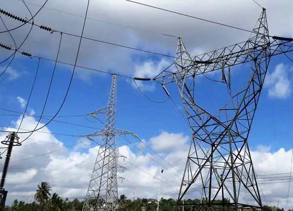
Power generation may come from coal plants, natural gas, hydroelectric stations, nuclear reactors, wind farms, solar facilities, and other technologies. Regardless of the source, the electricity produced must travel from remote generating stations to population centers. High-voltage transmission lines make this possible by carrying large amounts of energy efficiently over long distances. Constructed from aluminum or steel alloys, supported by towers, and engineered to survive severe weather, these lines allow regions to share resources and benefit from economies of scale.
The final stage of delivery occurs through the distribution system. Substations reduce voltage to safe, usable levels, transformers distribute energy across neighbourhoods, and distribution lines bring electricity directly to customers. Increasingly, homes and businesses also host small-scale generators such as rooftop solar or community wind installations. These sources feed power back into the distribution network or reduce local demand, creating a more adaptive and diverse system. For those new to supply technologies, overviews of how electricity is generated cover conventional and renewable pathways.
Increasing Electricity Grid Demand
As society's reliance on the electricity grid grows, the need to modernize it becomes more urgent. Smart grid technologies introduce sensors, digital communication, and analytical tools that improve visibility and control across the entire network. These systems allow utilities to detect problems quickly, respond to outages more efficiently, and integrate renewable resources that fluctuate with weather and daylight. Energy storage, whether in batteries or pumped hydro facilities, supports these changes by storing surplus energy and releasing it when supply dips or demand spikes.
Load balancing remains one of the most important responsibilities of electricity grid operators. Because electricity cannot be easily stockpiled without storage systems, production and consumption must stay aligned in real time. Forecasting tools, automated controls, and diversified generating sources all contribute to this balancing act. Markets and system operators coordinate schedules so that resources can be dispatched when needed, while maintaining strict voltage and frequency requirements.
The Eastern Interconnection links thousands of generating plants across the continent, forming one of the largest coordinated energy networks in the world. Its reach extends from the Atlantic coast toward the Rocky Mountain region, allowing electricity to flow across vast distances to support reliability, regional planning, and economic development.
Electricity grid reliability depends on more than technology. It requires strong engineering, maintenance practices, and robust emergency preparedness. Natural disasters, cyberattacks, equipment failures, and extreme weather can disrupt interconnected systems, so operators plan for contingencies and design redundancies to minimize impacts. Modernization efforts aim to increase system resilience while supporting growth in clean energy and electrification.
Frequently Asked Questions
What is an electricity grid, and how does it work?
A transmission and distribution system is a network that connects generating stations to end users and delivers electricity. High-voltage transmission lines carry energy across long distances, and substations reduce the voltage so distribution lines can safely deliver it to homes and businesses. The system must constantly match supply and demand, monitor equipment, and regulate voltage and frequency to maintain reliable service. For foundational clarity, a concise explainer on what electricity is helps connect basic concepts to electricity grid operations.
What is the difference between the transmission and distribution systems?
The transmission system moves large amounts of electrical energy over long distances using high-voltage systems designed for efficiency. The distribution system operates at lower voltages and delivers energy directly to consumers through local lines, transformers, and service equipment.
How is renewable energy integrated?
Wind, solar, and other renewable sources connect to the electricity grid through dedicated interconnection equipment at substations. Some resources are added to the system as distributed generation, producing electricity at or near the point of consumption. Operators manage variability using forecasting tools, energy storage, and flexible resource scheduling.
What are the challenges associated with maintaining the reliability and resilience of the T&D system?
Reliability depends on infrastructure strength, operational readiness, and rapid response capabilities. Severe weather, aging equipment, cyber risks, and variable output from renewable generation all pose challenges that require ongoing investment, monitoring, and planning.


What is a smart grid, and how does it differ from a traditional T&D system?
A smart electricity grid uses digital communication, sensors, and analytics to monitor conditions, automate decisions, and improve reliability. It enables two-way information flow between utilities and consumers, allowing more efficient energy use, faster restoration after outages, and better integration of renewables and storage.
How can energy storage be used to support the T&D system?
Storage can provide backup power, help regulate frequency and voltage, and store energy during periods of high generation for use when demand increases. It also supports renewable integration by smoothing fluctuations and supplying power when wind or sunlight is limited.
What is grid modernization, and why is it important for the future of the T&D system?
Electricity grid modernization upgrades infrastructure, communication networks, sensors, and control systems to support reliability, efficiency, sustainability, and resilience. These improvements prepare the system for growing electricity demand, renewable energy deployment, electrified transportation, and new technologies that depend on a stable, flexible grid.

