What is Impedance? Explained
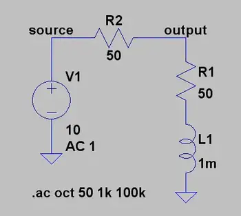

What is Impedance?

Impedance is the total opposition a cable or circuit offers to alternating current (AC). It combines resistance and reactance, measured in ohms (Ω), and determines how easily AC signals move through a circuit, affecting voltage, current, and power.


What is Impedance?

Impedance refers to the opposition that an electrical circuit presents to the flow of alternating current. It is a complex quantity that combines resistance and reactance, shaping how signals behave in AC systems.

✅ Combines resistance and reactance in AC circuits

✅ Measured in ohms and affects signal flow and power

✅ Essential in analyzing voltage, current, and circuit behavior


Understanding impedance (Z) is essential for anyone working with AC circuits. It influences how electrical energy flows, how efficiently components interact, and how systems handle varying frequencies. To understand how impedance interacts with voltage, explore our explanation of what is voltage and how it affects current flow in electrical circuits.

Electrical resistance is the opposition to direct current, while reactance opposes alternating current. Reactance arises from capacitors and inductors: capacitive reactance decreases with frequency, while inductive reactance increases. Together, these elements define the circuit’s impedance and its effect on current, voltage, and power transfer.

Impedance is crucial in AC circuit analysis because it enables engineers and technicians to calculate how voltage and current behave. This understanding facilitates efficient design, troubleshooting, and energy transfer, particularly when impedance matching is necessary for optimal performance. In AC systems, the behavior of inductors is described by inductance, which directly contributes to the reactive part of impedance.


Impedance Formula and Complex Representation

Impedance is defined mathematically by the formula:

Z = V / I

Where:

  • Z is impedance in ohms (Ω)

  • V is voltage (volts)

  • I is current (amperes)

This relationship is a natural extension of Ohm’s Law, which defines the link between voltage, current, and resistance in DC circuits. In AC analysis, impedance expands this concept by including reactance and phase angle.

In AC systems, impedance is expressed as a complex impedance:

Z = R + jX

Where:

  • R is resistance (real part)

  • X is reactance (imaginary part)

  • j is the imaginary unit

This representation accounts for both magnitude and phase angle, enabling the modelling of the interaction between voltage and current in AC circuits. Capacitors also play a key role, and understanding capacitance is essential to see how impedance decreases at higher frequencies.


Frequency, Phase Angle, and Reactance

Impedance depends on frequency. As frequency increases, reactance (especially inductive and capacitive) also changes, which shifts the phase angle between voltage and current.

  • Inductive reactance (XL = 2πfL) increases with frequency

  • Capacitive reactance (XC = 1 / 2πfC) decreases with frequency

As a result, the total impedance can change significantly depending on the signal. Engineers must consider this when analyzing harmonics or designing high-frequency systems. Learn how resistance contributes to impedance by reviewing what is electrical resistance and how it differs from reactance in AC systems.


Common Applications of Impedance

Understanding impedance is critical in many areas of electrical and electronic engineering:

  • Audio Systems: Proper impedance matching ensures maximum power transfer and sound clarity between amplifiers and speakers.

  • Radio Frequency (RF): Antenna design and transmission lines rely on precise impedance matching to minimize signal loss.

  • RLC Circuits: Impedance analysis enables tuning and resonance calculations in resistor-inductor-capacitor (RLC) networks.

  • Power Systems: Impedance affects fault current calculations, load flow, and harmonic analysis.

  • Phasor Analysis: Engineers use phasors to represent voltage and current in the frequency domain, relying on impedance to model AC behavior. For insights into the capacitive elements of impedance, see what is a capacitor and how it stores energy in electric fields.


Power System Impedance (Advanced)

At fundamental frequency, power systems are mostly inductive, and the equivalent impedance is often described as short-circuit reactance. While capacitive effects are typically minor in utility and industrial systems, they become significant in harmonic analysis. Short-circuit impedance, often derived from system studies, is a critical factor in these calculations.


Short-Circuit Reactance

If phase data is unavailable, engineers usually assume impedance is purely reactive—a reasonable approximation in many cases. However, transformer and line resistance may need to be considered for accurate harmonic modeling. The inductive reactance portion of impedance scales linearly with frequency, and engineers must carefully apply this when analyzing short-circuit conditions.


Transformer Resistance Effects

Resistance in transformers and conductors can change with frequency due to skin effect or eddy current losses. Large substation transformers, for example, may exhibit resistance that increases almost in proportion to frequency, which can help dampen resonance. In smaller transformers, winding resistance dominates and remains nearly constant until higher frequencies are reached. At utilization voltages, such as in industrial power systems, the service transformer’s impedance often accounts for more than 90% of total system impedance.

Transformer impedance in ohms can be estimated from the nameplate percentage impedance:

Z (Ω) = (Z% / 100) × (V² / kVA)

For instance, a 1,500 kVA transformer with a 6% impedance at 480 V has an equivalent impedance of approximately 9.22 Ω. This simplification is often sufficient to evaluate harmonic resonance risks and system behavior. For more on efficiency, review what the power factor is and its impact on AC systems.


Harmonic Considerations

One common mistake in harmonic analysis is neglecting to adjust reactance for frequency. The reactance at the h-th harmonic is determined from the fundamental reactance X1 by:

where h is the harmonic number and X1 is the fundamental reactance magnitude. (For capacitive branches specifically: XC,h = XC,1 / h, while inductive branches scale as XL,h = h × XL,1.)

In many power systems, resistance remains nearly unchanged up to the ninth harmonic. However, at higher frequencies, skin effect increases conductor resistance, and transformer eddy current losses further influence apparent resistance. These factors affect resonance conditions and can alter predictions of harmonic distortion.

Neglecting resistance generally yields a conservative, higher prediction of distortion. But when transformer effects dominate system behavior, resistance should be modeled more carefully. Impedance matching is especially important in such cases for ensuring stability and avoiding resonance issues in AC power systems. The impact of impedance extends to system-level issues like harmonic distortion, which can affect stability and power quality if not managed correctly.


Calculating Total Impedance

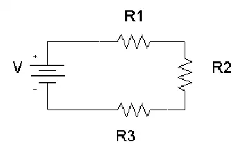
The total impedance (Z_total) of a circuit depends on how elements are connected:

Series circuits:

Z_total = √ (R_total² + (X_L – X_C)²)

Parallel circuits:

Z_total = 1 / (1/Z₁ + 1/Z₂ + …)

These calculations follow the same principles as Ohm’s Law, but are adapted for AC circuits where both resistance and reactance determine the current flow. By combining these components, engineers can predict circuit response, design filters, and ensure efficient energy transfer. Calculating impedance is a crucial part of power system analysis, where accurate models enable the prediction of current flow, voltage stability, and fault levels.


Impedance Matching and Spectroscopy

Impedance matching adjusts the source and load to the same impedance, maximizing power transfer and minimizing reflections. It is essential in audio systems, RF communications, and transmission line design.

Impedance spectroscopy extends the concept further, analyzing a material or device across a range of frequencies. This method reveals electrical properties such as conductivity, dielectric response, and electrochemical behavior, guiding the design of advanced materials and devices.


Conclusion

Impedance is a cornerstone of AC circuit analysis, uniting resistance and reactance into a single complex value that varies with frequency. From audio clarity to power system stability, impedance shapes how electricity flows and interacts in real-world systems. By mastering impedance—whether matching speaker loads, modeling harmonic resonance, or studying material properties—engineers and technicians can design more efficient, reliable, and safe electrical systems.


Related Articles


Related News

What is Electric Load

Electric load refers to the amount of electrical power consumed by devices in a system. It determines demand on the power supply and affects energy distribution, efficiency, and system design.


What is Electric Load?

✅ Measures the power consumed by electrical devices or systems

✅ Impacts system design, energy use, and load management

✅ Varies by time, usage patterns, and connected equipment

What is electric load? It refers to the total power demand placed on a circuit by connected devices. Electric load, such as lighting, motors, and appliances, impacts energy use, system sizing, and overall efficiency across residential, commercial, and industrial settings.

An electric load refers to any device or system that consumes electric power to perform work, such as an electric motor, lighting fixture, or household electrical appliances. These loads draw electrical energy from the power source, impacting both system efficiency and capacity planning. Accurate electrical load calculation is crucial for designing circuits, selecting the correct breakers, and ensuring safe operation in homes, businesses, and industrial facilities. Using real-time monitoring tools, engineers can assess load patterns, identify peak demand, and implement energy-saving strategies through smart load management systems.

An electric load can be anything that consumes power, such as lights, appliances, heating systems, motors, and computers. In electrical engineering, a load represents the demand that a device or installation places on the power source.

Electric load is closely influenced by regional consumption patterns, which can be explored in more detail in Electricity Demand in Canada, highlighting how climate and industry shape national power usage.

Different types of types exist, and they are classified based on their characteristics. Resistive loads include, for example, converting energy directly into heat, such as heaters or incandescent light bulbs. Inductive loads, however, require energy to create a magnetic field, such as motors or transformers. Capacitive loads, meanwhile, store and release energy, such as capacitors used in a powered circuit.


An electric load refers to any device or circuit that consumes energy in a system. A common example is a load that consists of appliances such as heaters or ovens, where the primary component is a heating element. This heating element converts energy into heat, providing warmth or cooking power. It consists of a heating mechanism that demands specific amounts of powered energy depending on the device’s power requirements, which is crucial for maintaining an efficient and balanced system. For readers new to electrical concepts, the Basic Electricity Handbook provides foundational knowledge that helps contextualize the meaning of electricity in power systems.


Types of Electrical Loads

Electric loads fall into three primary categories:

  • Resistive: Devices like incandescent light bulbs, heaters, and toasters. These convert energy directly into heat.

  • Inductive: Motors, transformers, and fans. Inductive loads create magnetic fields to operate, often resulting in a lagging power factor.

  • Capacitive: Capacitors are used in power factor correction equipment or some specialized electronic devices. They store energy temporarily.

Each load type interacts differently with the system, impacting both efficiency and stability.

Related: Understand how resistive loads behave in a circuit.


How to Calculate Electric Load

Accurately calculating electric load is important for selecting the correct wire size, circuit breakers, and transformer ratings.


For example:

  • If a device operates at 120 volts and draws 5 amps:

    • Load = 120 × 5 = 600 watts


Step-by-Step Example for a Household Circuit:

  1. Add up the wattage of all devices on the circuit.

  2. Divide the total wattage by the system voltage to find the total current load.

  3. Compare the load to the circuit breaker rating to ensure it is not overloaded.

Tip: Always design for 80% of breaker capacity for safety.


Why Understanding Electric Load Matters

Understanding electric load has real-world implications:

  • Energy Bills: Higher demand results in higher costs, particularly for businesses subject to demand charges.

  • System Design: Correct assessment ensures that wiring, transformers, and protection devices are appropriately sized.

  • Power Quality: Poor management can lead to low power factor, voltage drops, and even system instability.

  • Maintenance Planning: Predictable loads extend the life of equipment and reduce costly downtime.


Management Strategies

Smart load management can improve system efficiency and reduce costs:

  • Peak Shaving: Reducing consumption during periods of high demand.

  • Shifting: Moving heavy loads to off-peak hours.

  • Power Factor Correction: Installing capacitors to improve system efficiency and lower bills.


Electric load is a critical concept in both residential and industrial settings. By understanding the types of calculations used to determine total demand and the practical impacts on energy costs and system design, you can build safer, more efficient systems.

One critical aspect is the power factor. Power factor is the ratio of active power (measured in watts) to apparent power (measured in volt-amperes). In simpler terms, it is the efficiency of energy usage. A low power factor indicates that a device or system consumes energy more than necessary to perform a given task, leading to higher energy costs and increased strain on the power grid. The relationship between load, bill, and motor is especially evident in provincial models, such as Ontario’s Electricity Cost Allocation, which explains how peak demand affects consumer rates.

An electric load is a critical concept in the design and operation of the power grid. Understanding how it is measured, the different types, power factor, management strategies, peak, shedding, and demand response programs are essential for optimizing the use of the grid and ensuring its reliability. By balancing the demand for power with the grid's capacity, we can reduce energy costs, prevent blackouts, and create a more sustainable energy system. Management is a critical component of infrastructure planning, as discussed in the Transmission & Distribution Channel, which examines how levels affect grid design and performance.

In industrial environments, managing efficiently can lead to significant cost savings and operational stability. Explore these strategies in the Industrial Electric Power Channel.


View more

What is Electrical Resistance?

Electrical resistance is the measure of how much a material opposes the flow of electric current. Measured in ohms (Ω), it affects voltage, limits current, and plays a vital role in circuit function, energy loss, and power distribution.


What is Electrical Resistance?

Electrical resistance is a key concept in electronics that limits the flow of electricity through a conductor.

✅ Measured in ohms (Ω) to indicate opposition to current flow

✅ Affects voltage, current, and overall power efficiency

✅ Essential in designing safe and effective electrical circuits


Electrical Resistance is an electrical quantity that measures how a device or material reduces the flow of electric current through it. The resistance is measured in units of ohms (Ω). If we make an analogy to water flow in pipes, the resistance is greater when the pipe is thinner, so the water flow is decreased.

Electrical Resistance is a measure of the opposition that a circuit offers to the flow of electric current. You might compare it to the diameter of a hose. In fact, for metal wire, this is an excellent analogy: small-diameter wire has high resistance (a lot of opposition to current flow), while large-diameter wire has low resistance (relatively little opposition to electric currents). Of course, the type of metal makes a difference, too. Iron wire has higher resistance for a given diameter than copper wire. Nichrome wire has still more resistance.

Electrical resistance is the property of a material that opposes the flow of electric current. The resistance of a conductor depends on factors such as the conducting material and its cross-sectional area. A larger cross-sectional area allows more current to flow, reducing resistance, while a smaller area increases it. The unit of electrical resistance is the ohm (Ω), which measures the degree to which a material impedes the flow of electric charge. Conductors with low resistance are essential for efficient electrical systems.


What causes electrical resistance?

An electric current flows when electrons move through a conductor, such as a metal wire. The moving electrons can collide with the ions in the metal. This makes it more difficult for the current to flow, and causes resistance.


Why is electrical resistance important?

Therefore, it is sometimes useful to add components called resistors into an electrical circuit to restrict the flow of electricity and protect the components in the circuit. Resistance is also beneficial because it allows us to shield ourselves from the harmful effects of electricity.

The standard unit of resistance is the ohm. This is sometimes abbreviated by the upper-case Greek letter omega, resembling an upside-down capital U (Ω). In this article, we'll write it out as "ohm" or "ohms."

You'll sometimes hear about kilohms, where 1 kilohm = 1,000 ohms, or about megohms, where 1 megohm = 1,000 kilohms = 1,000,000 ohms.

Electric wire is sometimes rated for resistivity. The standard unit for this purpose is the ohm per foot (ohm/ft) or the ohm per meter (ohm/m). You may also encounter the unit of ohms per kilometre (ohm/km). 

When an IV is placed across 1 ohm of resistance, assuming the power supply can deliver an unlimited number of charge carriers, there will be a current of 1 A. If the re­sistance is doubled, the current is halved. If the resistance is cut in half, the current doubles. Therefore, the current flow, for a constant voltage, is inversely proportional to the resistance. 

Typically, four-terminal resistors are used to measure current by measuring the voltage drop between the voltage terminals with current flowing through the current terminals. These standards, designed for use with potentiometers for precision current measurement, correspond in structure to the shunts used with millivoltmeters for current measurement with indicating instruments. Current standards must be designed to dissipate the heat they develop at rated current, with only a small temperature rise. They may be oil- or air-cooled; the latter design has a much greater surface area, as heat transfer to still air is less efficient than to oil. An air-cooled current standard with a 20 μω resistance and 2000 A capacity has an accuracy of 0.04%. Very low-resistance oil-cooled standards are mounted in individual oil-filled containers, provided with copper coils through which cooling water is circulated and with propellers to provide continuous oil motion.

Related Articles


View more

Electricity How it Works

Electricity How It Works explains electron flow, voltage, current, resistance, and power in circuits, from generation to distribution, covering AC/DC systems, Ohm's law, conductors, semiconductors, transformers, and energy conversion efficiency and safety.


What Is Electricity How It Works?

Explains electron flow, voltage, current, resistance, and power conversion in AC/DC circuits and key components.

✅ Voltage drives current through resistance per Ohm's law (V=IR).

✅ AC/DC systems distribute power via transformers and rectifiers.

✅ Conductors, semiconductors, capacitors, inductors shape circuits.


Electricity How It Works - This is a very common question. It can best be explained by stating this way: Single-phase electricity is what you have in your house. You generally talk about household electrical service as single-phase, 120-volt AC service. If you use an oscilloscope and look at the power found at a normal wall-plate outlet in your house, what you will find is that the power at the wall plate looks like a sine wave, and that wave oscillates between -170 volts and 170 volts (the peaks are indeed at 170 volts; it is the effective (rms) voltage that is 120 volts). The rate of oscillation for the sine wave is 60 cycles per second. Oscillating power like this is generally referred to as AC, or alternating current. The alternative to AC is DC, or direct current. Batteries produce DC: A steady stream of electrons flows in one direction only, from the negative to the positive terminal of the battery.

For a refresher on fundamentals, the overview at what is electricity explains charge, current, and voltage in practical terms.

AC has at least three advantages over DC in an electricity power distribution grid:

1. Large electricity generators happen to generate AC naturally, so conversion to DC would involve an extra step.
2. Electrical Transformers must have alternating current to operate, and we will see that the power distribution grid depends on transformers. 
3. It is easy to convert AC to DC but expensive to convert DC to AC, so if you were going to pick one or the other AC would be the better choice.

To connect these advantages to real-world practice, the primer on basic electricity clarifies AC versus DC behavior, impedance, and safety basics.

The electricity generating plant, therefore, produces AC. For a deeper look at how rotating machines induce AC, see the overview of electricity generators and their role in utility-scale plants.


Electricity How it Works in The Power Plant: Three-phase Power

If you want a quick walkthrough from generation to loads, this guide on how electricity works ties the concepts together before we examine three-phase specifics.

The power plant produces three different phases of AC power simultaneously, and the three phases are offset 120 degrees from each other. There are four wires coming out of every power plant: the three phases plus a neutral or ground common to all three. If you were to look at the three phases on a graph, they would look like this relative to ground:

A concise visual explainer on three-phase electricity shows how 120-degree phase offsets create balanced currents in feeders.

Electricity How It Works - There is nothing magical about three-phase power. It is simply three single phases synchronized and offset by 120 degrees. For wiring diagrams and common configurations, explore 3-phase power examples used across industrial facilities.

Why three phases? Why not one or two or four? In 1-phase and 2-phase electricity, there are 120 moments per second when a sine wave is crossing zero volts. In 3-phase power, at any given moment one of the three phases is nearing a peak. High-power 3-phase motors (used in industrial applications) and things like 3-phase welding equipment therefore have even power output. Four phases would not significantly improve things but would add a fourth wire, so 3-phase is the natural settling point.

Practical comparisons of motor torque ripple and line loading in 3-phase electricity help illustrate why three conductors strike the best balance.

And what about this "ground," as mentioned above? The power company essentially uses the earth as one of the wires in the electricity system. The earth is a pretty good conductor and it is huge, so it makes a good return path for electrons. (Car manufacturers do something similar; they use the metal body of the car as one of the wires in the car's electrical system and attach the negative pole of the battery to the car's body.) "Ground" in the power distribution grid is literally "the ground" that's all around you when you are walking outside. It is the dirt, rocks, groundwater, etc., of the earth.


Related Articles

View more

What is Impedance? Explained

Impedance is the total opposition a cable or circuit offers to alternating current (AC). It combines resistance and reactance, measured in ohms (Ω), and determines how easily AC signals move through a circuit, affecting voltage, current, and power.


What is Impedance?

Impedance refers to the opposition that an electrical circuit presents to the flow of alternating current. It is a complex quantity that combines resistance and reactance, shaping how signals behave in AC systems.

✅ Combines resistance and reactance in AC circuits

✅ Measured in ohms and affects signal flow and power

✅ Essential in analyzing voltage, current, and circuit behavior


Understanding impedance (Z) is essential for anyone working with AC circuits. It influences how electrical energy flows, how efficiently components interact, and how systems handle varying frequencies. To understand how impedance interacts with voltage, explore our explanation of what is voltage and how it affects current flow in electrical circuits.

Electrical resistance is the opposition to direct current, while reactance opposes alternating current. Reactance arises from capacitors and inductors: capacitive reactance decreases with frequency, while inductive reactance increases. Together, these elements define the circuit’s impedance and its effect on current, voltage, and power transfer.

Impedance is crucial in AC circuit analysis because it enables engineers and technicians to calculate how voltage and current behave. This understanding facilitates efficient design, troubleshooting, and energy transfer, particularly when impedance matching is necessary for optimal performance. In AC systems, the behavior of inductors is described by inductance, which directly contributes to the reactive part of impedance.


Impedance Formula and Complex Representation

Impedance is defined mathematically by the formula:

Z = V / I

Where:

  • Z is impedance in ohms (Ω)

  • V is voltage (volts)

  • I is current (amperes)

This relationship is a natural extension of Ohm’s Law, which defines the link between voltage, current, and resistance in DC circuits. In AC analysis, impedance expands this concept by including reactance and phase angle.

In AC systems, impedance is expressed as a complex impedance:

Z = R + jX

Where:

  • R is resistance (real part)

  • X is reactance (imaginary part)

  • j is the imaginary unit

This representation accounts for both magnitude and phase angle, enabling the modelling of the interaction between voltage and current in AC circuits. Capacitors also play a key role, and understanding capacitance is essential to see how impedance decreases at higher frequencies.


Frequency, Phase Angle, and Reactance

Impedance depends on frequency. As frequency increases, reactance (especially inductive and capacitive) also changes, which shifts the phase angle between voltage and current.

  • Inductive reactance (XL = 2πfL) increases with frequency

  • Capacitive reactance (XC = 1 / 2πfC) decreases with frequency

As a result, the total impedance can change significantly depending on the signal. Engineers must consider this when analyzing harmonics or designing high-frequency systems. Learn how resistance contributes to impedance by reviewing what is electrical resistance and how it differs from reactance in AC systems.


Common Applications of Impedance

Understanding impedance is critical in many areas of electrical and electronic engineering:

  • Audio Systems: Proper impedance matching ensures maximum power transfer and sound clarity between amplifiers and speakers.

  • Radio Frequency (RF): Antenna design and transmission lines rely on precise impedance matching to minimize signal loss.

  • RLC Circuits: Impedance analysis enables tuning and resonance calculations in resistor-inductor-capacitor (RLC) networks.

  • Power Systems: Impedance affects fault current calculations, load flow, and harmonic analysis.

  • Phasor Analysis: Engineers use phasors to represent voltage and current in the frequency domain, relying on impedance to model AC behavior. For insights into the capacitive elements of impedance, see what is a capacitor and how it stores energy in electric fields.


Power System Impedance (Advanced)

At fundamental frequency, power systems are mostly inductive, and the equivalent impedance is often described as short-circuit reactance. While capacitive effects are typically minor in utility and industrial systems, they become significant in harmonic analysis. Short-circuit impedance, often derived from system studies, is a critical factor in these calculations.


Short-Circuit Reactance

If phase data is unavailable, engineers usually assume impedance is purely reactive—a reasonable approximation in many cases. However, transformer and line resistance may need to be considered for accurate harmonic modeling. The inductive reactance portion of impedance scales linearly with frequency, and engineers must carefully apply this when analyzing short-circuit conditions.


Transformer Resistance Effects

Resistance in transformers and conductors can change with frequency due to skin effect or eddy current losses. Large substation transformers, for example, may exhibit resistance that increases almost in proportion to frequency, which can help dampen resonance. In smaller transformers, winding resistance dominates and remains nearly constant until higher frequencies are reached. At utilization voltages, such as in industrial power systems, the service transformer’s impedance often accounts for more than 90% of total system impedance.

Transformer impedance in ohms can be estimated from the nameplate percentage impedance:

Z (Ω) = (Z% / 100) × (V² / kVA)

For instance, a 1,500 kVA transformer with a 6% impedance at 480 V has an equivalent impedance of approximately 9.22 Ω. This simplification is often sufficient to evaluate harmonic resonance risks and system behavior. For more on efficiency, review what the power factor is and its impact on AC systems.


Harmonic Considerations

One common mistake in harmonic analysis is neglecting to adjust reactance for frequency. The reactance at the h-th harmonic is determined from the fundamental reactance X1 by:

where h is the harmonic number and X1 is the fundamental reactance magnitude. (For capacitive branches specifically: XC,h = XC,1 / h, while inductive branches scale as XL,h = h × XL,1.)

In many power systems, resistance remains nearly unchanged up to the ninth harmonic. However, at higher frequencies, skin effect increases conductor resistance, and transformer eddy current losses further influence apparent resistance. These factors affect resonance conditions and can alter predictions of harmonic distortion.

Neglecting resistance generally yields a conservative, higher prediction of distortion. But when transformer effects dominate system behavior, resistance should be modeled more carefully. Impedance matching is especially important in such cases for ensuring stability and avoiding resonance issues in AC power systems. The impact of impedance extends to system-level issues like harmonic distortion, which can affect stability and power quality if not managed correctly.


Calculating Total Impedance

The total impedance (Z_total) of a circuit depends on how elements are connected:

Series circuits:

Z_total = √ (R_total² + (X_L – X_C)²)

Parallel circuits:

Z_total = 1 / (1/Z₁ + 1/Z₂ + …)

These calculations follow the same principles as Ohm’s Law, but are adapted for AC circuits where both resistance and reactance determine the current flow. By combining these components, engineers can predict circuit response, design filters, and ensure efficient energy transfer. Calculating impedance is a crucial part of power system analysis, where accurate models enable the prediction of current flow, voltage stability, and fault levels.


Impedance Matching and Spectroscopy

Impedance matching adjusts the source and load to the same impedance, maximizing power transfer and minimizing reflections. It is essential in audio systems, RF communications, and transmission line design.

Impedance spectroscopy extends the concept further, analyzing a material or device across a range of frequencies. This method reveals electrical properties such as conductivity, dielectric response, and electrochemical behavior, guiding the design of advanced materials and devices.


Conclusion

Impedance is a cornerstone of AC circuit analysis, uniting resistance and reactance into a single complex value that varies with frequency. From audio clarity to power system stability, impedance shapes how electricity flows and interacts in real-world systems. By mastering impedance—whether matching speaker loads, modeling harmonic resonance, or studying material properties—engineers and technicians can design more efficient, reliable, and safe electrical systems.


Related Articles


View more

Who Discovered Electricity

Who discovered electricity? Early pioneers including William Gilbert, Benjamin Franklin, Luigi Galvani, Alessandro Volta, and Michael Faraday advanced static electricity, circuits, and electromagnetism, laying the foundation for modern electrical science.


Who Discovered Electricity?

No single person discovered electricity; figures Gilbert, Franklin, Galvani, Volta and Faraday shaped the field.

✅ William Gilbert coined "electricus"; foundational studies of magnetism.

✅ Franklin's kite experiment linked lightning and electricity; charge theory.

✅ Volta's pile enabled current; Faraday unified electromagnetism.


Who Discovered Electricity ? From the writings of Thales of Miletus it appears that Westerners in their day knew as long ago as 600 B.C. that amber becomes charged by rubbing. But other than that, there was little real progress until the English scientist William Gilbert in 1600 described the electrification of many substances and coined the term "electricity" from the Greek word for amber. For a deeper look at how ideas about discovery versus invention evolved, see who invented electricity for historical perspective.

As a result, Gilbert is called the father of modern electric power. In 1660, Otto von Guericke invented a crude machine for producing static electricity. It was a ball of sulfur, rotated by a crank with one hand and rubbed with the other. Successors, such as Francis Hauksbee, made improvements that provided experimenters with a ready source of static electricity. Today's highly developed descendant of these early machines is the Van de Graaf generator, which is sometimes used as a particle accelerator. Robert Boyle realized that attraction and repulsion were mutual and that electric force was transmitted through a vacuum. Stephen Gray distinguished between conductors and nonconductors. C. F. Du Fay recognized two kinds of power, which Benjamin Franklin and Ebenezer Kinnersley of Philadelphia, peoples who later named positive and negative.

For a quick chronological overview of these pioneering advances, consult this timeline of electricity to trace developments across centuries.

Progress quickened after the Leyden jar was invented in 1745 by Pieter van Musschenbroek. The Leyden jar stored static electricity, which could be discharged all at once. In 1747 William Watson discharged a Leyden jar through a circuit, and comprehension of the current and circuit started a new field of experimentation. Henry Cavendish, by measuring the conductivity of materials (he compared the simultaneous shocks he received by discharging Leyden jars through the materials), and Charles A. Coulomb, by expressing mathematically the attraction of electrified bodies, began the quantitative study of electric power. For additional background on early experiments and theory, explore the history of electricity for context and sources.

Depite what you have learned, Benjamin Franklin did not "discover" electric power. In fact, electric power did not begin when Benjamin Franklin at when he flew his kite during a thunderstorm or when light bulbs were installed in houses all around the world. For details on why Franklin is often miscredited, read did Ben Franklin discover electricity for clarification.

The truth is that electric power has always been around because it naturally exists in the world. Lightning, for instance, is simply a flow of electrons between the ground and the clouds. When you touch something and get a shock, that is really static electricity moving toward you. If you are new to the core concepts, start with basic electricity to ground the fundamentals.

Power Personalities


Benjamin Franklin

Ben Franklin was an American writer, publisher, scientist and diplomat, who helped to draw up the famous Declaration of Independence and the US Constitution. In 1752 Franklin proved that lightning and the spark from amber were one and the same thing. The story of this famous milestone is a familiar one, in which Franklin fastened an iron spike to a silken kite, which he flew during a thunderstorm, while holding the end of the kite string by an iron key. When lightening flashed, a tiny spark jumped from the key to his wrist. The experiment proved Franklin's theory. For more about Franklin's experiments, see Ben Franklin and electricity for experiment notes and legacy.


Galvani and Volta

In 1786, Luigi Galvani, an Italian professor of medicine, found that when the leg of a dead frog was touched by a metal knife, the leg twitched violently. Galvani thought that the muscles of the frog must contain electric signals. By 1792 another Italian scientist, Alessandro Volta, disagreed: he realised that the main factors in Galvani's discovery were the two different metals - the steel knife and the tin plate - apon which the frog was lying. Volta showed that when moisture comes between two different metals, electric power is created. This led him to invent the first electric battery, the voltaic pile, which he made from thin sheets of copper and zinc separated by moist pasteboard.

In this way, a new kind of electric power was discovered, electric power that flowed steadily like a current of water instead of discharging itself in a single spark or shock. Volta showed that electric power could be made to travel from one place to another by wire, thereby making an important contribution to the science of electricity. The unit of electrical potential, the Volt, is named after Volta.


Michael Faraday

The credit for generating electric current on a practical scale goes to the famous English scientist, Michael Faraday. Faraday was greatly interested in the invention of the electromagnet, but his brilliant mind took earlier experiments still further. If electricity could produce magnetism, why couldn't magnetism produce electric power.

In 1831, Faraday found the solution. Electricity could be produced through magnetism by motion. He discovered that when a magnet was moved inside a coil of copper wire, a tiny electric current flows through the wire. Of course, by today's standards, Faraday's electric dynamo or electric generator was crude, and provided only a small electric current be he discovered the first method of generating electric power by means of motion in a magnetic field.


Thomas Edison and Joseph Swan

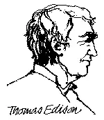
Nearly 40 years went by before a really practical DC (Direct Current) generator was built by Thomas Edison in America. Edison's many inventions included the phonograph and an improved printing telegraph. In 1878 Joseph Swan, a British scientist, invented the incandescent filament lamp and within twelve months Edison made a similar discovery in America. For a broader view of his role in power systems, visit Thomas Edison and electricity for projects and impact.

Swan and Edison later set up a joint company to produce the first practical filament lamp. Prior to this, electric lighting had been my crude arc lamps.

Edison used his DC generator to provide electricity to light his laboratory and later to illuminate the first New York street to be lit by electric lamps, in September 1882. Edison's successes were not without controversy, however - although he was convinced of the merits of DC for generating electricity, other scientists in Europe and America recognised that DC brought major disadvantages.


George Westinghouse and Nikola Tesl

Westinghouse was a famous American inventor and industrialist who purchased and developed Nikola Tesla's patented motor for generating alternating current. The work of Westinghouse, Tesla and others gradually persuaded American society that the future lay with AC rather than DC (Adoption of AC generation enabled the transmission of large blocks of electrical, power using higher voltages via transformers, which would have been impossible otherwise). Today the unit of measurement for magnetic fields commemorates Tesla's name.


James Watt

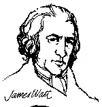
When Edison's generator was coupled with Watt's steam engine, large scale electricity generation became a practical proposition. James Watt, the Scottish inventor of the steam condensing engine, was born in 1736. His improvements to steam engines were patented over a period of 15 years, starting in 1769 and his name was given to the electric unit of power, the Watt.
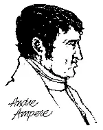
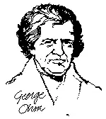
Watt's engines used the reciprocating piston, however, today's thermal power stations use steam turbines, following the Rankine cycle, worked out by another famous Scottish engineer, William J.M Rankine, in 1859.


Andre Ampere and George Ohm

Andre Marie Ampere, a French mathematician who devoted himself to the study of electricity and magnetism, was the first to explain the electro-dynamic theory. A permanent memorial to Ampere is the use of his name for the unit of electric current.

George Simon Ohm, a German mathematician and physicist, was a college teacher in Cologne when in 1827 he published, "The galvanic Circuit Investigated Mathematically". His theories were coldly received by German scientists but his research was recognised in Britain and he was awarded the Copley Medal in 1841. His name has been given to the unit of electrical resistance.

Go here to visit all of our Electrical Energy pages.


Related Articles

View more

Define Electromagnetism

Electromagnetism is the branch of physics that studies the interaction between electric currents and magnetic fields. It explains how electricity generates magnetism and powers devices such as motors, generators, and transformers in modern electrical systems.


How Should We Define Electromagnetism?

Here's a good way to define electromagnetism: Electromagnetism is a branch of physics involving the study of the electromagnetic force, a type of physical interaction that occurs between electrically charged particles.

✅ Explains the relationship between electricity and magnetism

✅ Governs the operation of motors, generators, and transformers

✅ Forms the basis for electromagnetic waves like light and radio

The electromagnetic force is carried by electromagnetic fields, which are composed of electric fields and magnetic fields, and it is responsible for electromagnetic radiation, such as light.


Who Discovered Electromagnetism?

In 1820, the Danish physicist, Hans Christian Oersted, discovered that the needle of a compass brought near a current-carrying conductor would be deflected. When the current flow stopped, the compass needle returned to its original position. This important discovery demonstrated a relationship between electricity and magnetism that led to the development of the electromagnet and to many of the inventions on which modern industry is based.

Oersted discovered that the magnetic field had no connection with the conductor in which the electrons were flowing, because the conductor was made of nonmagnetic copper. The electrons moving through the wire created the magnetic field around the conductor. Since a magnetic field accompanies a charged particle, the greater the current flow, the greater the magnetic field. Figure 1 illustrates the magnetic field around a current-carrying wire. A series of concentric circles around the conductor represents the field, which, if all the lines were shown, would appear more as a continuous cylinder of such circles around the conductor.


Fig. 1 - Magnetic field formed around a conductor in which current is flowing.


As long as current flows in the conductor, the lines of force remain around it. [Figure 2] If a small current flows through the conductor, there will be a line of force extending out to circle A. If the current flow is increased, the line of force will increase in size to circle B, and a further increase in current will expand it to circle C. As the original line (circle) of force expands from circle A to B, a new line of force will appear at circle A. As the current flow increases, the number of circles of force increases, expanding the outer circles farther from the surface of the current-carrying conductor.


Fig. 2 - Expansion of magnetic field as current increases.


If the current flow is a steady, nonvarying direct current, the magnetic field remains stationary. When the current stops, the magnetic field collapses, and the magnetism around the conductor disappears.

A compass needle is used to demonstrate the direction of the magnetic field around a current-carrying conductor. Figure 3 View A shows a compass needle positioned at right angles to, and approximately one inch from, a current-carrying conductor. If no current were flowing, the north-seeking end of the compass needle would point toward the Earth’s magnetic pole. When current flows, the needle lines itself up at right angles to a radius drawn from the conductor. Since the compass needle is a small magnet, with lines of force extending from south to north inside the metal, it will turn until the direction of these lines agrees with the direction of the lines of force around the conductor. As the compass needle is moved around the conductor, it will maintain itself in a position at right angles to the conductor, indicating that the magnetic field around a current-carrying conductor is circular. As shown in View B of Figure 3, when the direction of current flow through the conductor is reversed, the compass needle points in the opposite direction, indicating that the magnetic field has reversed its direction.


Fig.3 - Magnetic field around a current-carrying conductor.


A method for determining the direction of the lines of force when the direction of current flow is known is illustrated in Figure 4. If the conductor is grasped in the left hand, with the thumb pointing in the direction of current flow, the fingers will be wrapped around the conductor in the same direction as the lines of the magnetic field. This is called the left-hand rule.


Fig.4 - Left-hand rule.


Although it has been stated that the lines of force have direction, this should not be construed to mean that the lines have motion in a circular direction around the conductor. Although the lines of force tend to act in a clockwise or counterclockwise direction, they are not revolving around the conductor.

Since current flows from negative to positive, many illustrations indicate the current direction with a dot symbol on the end of the conductor when the electrons are flowing toward the observer and a plus sign when the current is flowing away from the observer. [Figure 5]


Fig. 5 - Direction of current flow in a conductor.


When a wire is bent into a loop and an electric current flows through it, the left-hand rule remains valid. [Figure 6]


Fig. 6 - Magnetic field around a looped conductor.


If the wire is coiled into two loops, many of the lines of force become large enough to include both loops. Lines of force go through the loops in the same direction, circle around the outside of the two coils, and come in at the opposite end. [Figure 7]


Fig. 7 - Magnetic field around a conductor with two loops.


When a wire contains many such loops, it is referred to as a coil. The lines of force form a pattern through all the loops, causing a high concentration of flux lines through the center of the coil. [Figure 8]


Fig. 8 - Magnetic field of a coil.


In a coil made from loops of a conductor, many of the lines of force are dissipated between the loops of the coil. By placing a soft iron bar inside the coil, the lines of force will be concentrated in the center of the coil, since soft iron has a greater permeability than air. [Figure 9] This combination of an iron core in a coil of wire loops, or turns, is called an electromagnet, since the poles (ends) of the coil possess the characteristics of a bar magnet.


Fig. 9 - Electromagnet.


The addition of the soft iron core does two things for the current-carrying coil. First, the magnetic flux increases, and second, the flux lines become more concentrated.

When direct current flows through the coil, the core becomes magnetized with the same polarity (north and south poles) as the coil would have without the core. If the current is reversed, the polarity will also be reversed.

The polarity of the electromagnet is determined by the left-hand rule in the same manner as the polarity of the coil without the core was determined. If the coil is grasped in the left hand in such a manner that the fingers curve around the coil in the direction of electron flow (minus to plus), the thumb will point in the direction of the north pole. [Figure 10]


Fig. 10 - Left-hand rule applied to a coil.

The strength of the magnetic field of the electromagnet can be increased by either increasing the flow of current or the number of loops in the wire. Doubling the current flow approximately doubles the strength of the field, and similarly, doubling the number of loops approximately doubles the magnetic field strength. Finally, the type of metal in the core is a factor in the field strength of the electromagnet.

A soft iron bar is attracted to either pole of a permanent magnet and, likewise, is attracted by a current-carrying coil. The lines of force extend through the soft iron, magnetizing it by induction and pulling the iron bar toward the coil. If the bar is free to move, it will be drawn into the coil to a position near the center where the field is strongest. [Figure 10-35]


Fig. 11 - Solenoid with iron core.


Electromagnets are utilized in various electrical instruments, including motors, generators, relays, and other devices. Some electromagnetic devices operate on the principle that an iron core, held away from the center of a coil, will be rapidly pulled into its center position when the coil is energized. This principle is utilized in the solenoid, also known as a solenoid switch or relay, where the iron core is spring-loaded off-center and moves to complete a circuit when the coil is energized. 


Related Articles


View more

Sign Up for Electricity Forum’s Newsletter

Stay informed with our FREE Newsletter — get the latest news, breakthrough technologies, and expert insights, delivered straight to your inbox.

Electricity Today T&D Magazine Subscribe for FREE

Stay informed with the latest T&D policies and technologies.
  • Timely insights from industry experts
  • Practical solutions T&D engineers
  • Free access to every issue

Download the 2025 Electrical Training Catalog

Explore 50+ live, expert-led electrical training courses –

  • Interactive
  • Flexible
  • CEU-cerified