Line Leakage Testing: Is It Right For Your Application
By Colin P. Hurst, Associate Publisher
By Colin P. Hurst, Associate Publisher
Line leakage testing evaluates unintended current paths under normal and single-fault conditions, ensuring electrical safety, touch current compliance, insulation integrity, and adherence to IEC 60990, IEC 60601, UL standards for equipment and medical devices.
The Line Leakage test (LLT for short) is most often specified to be performed as a type test in a design or engineering laboratory or as a routine production line test on medical devices right before they ship. Not as commonly performed as a Dielectric Withstand or Ground Bond test in a production environment, LLT can cause some confusion for engineers and technicians alike.
However, technological advancements have begun to lessen the outward complexity of the test. For a practical overview of modern platforms, the electrical safety testers directory highlights integrated features used to streamline LLT procedures in production.
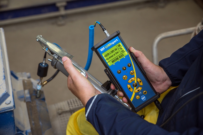
What used to be complicated set-ups and testing procedures has now been simplified with the use of multi-function testing instruments, all-in-one testing solutions equipped with the components and relay switching networks to perform leakage tests in an automated sequence with little or no input from the test operator. This makes for safer and more efficient testing.
Integrating such instruments into a broader quality program is easier when the electrical testing best practices are mapped to standardized workflows and record-keeping.
Electrical products including anything from appliances to handheld tools must be tested during the design and development phase in order to receive a safety agency listing. In these laboratory environments, the LLT is used to help ensure that the product’s manufacturing processes and assembly practices are satisfactory. Along with other common tests such as the Hipot and Ground Bond tests, the Line Leakage test is used in this situation primarily as an indicator of design quality. Design teams often cross-reference the dielectric voltage withstand test parameters to set conservative leakage screening limits during prototyping.

Some products, such as medical equipment, are designed with the intention of direct contact with a patient. Line Leakage tests should be performed on these products as a 100% routine production line test. Due to the sensitive nature of the applications for which this type of equipment is used, it is easy to see why rigorous testing must be performed as a routine test.
To establish safe baselines before patient-connected trials, a dedicated insulation resistance tester can verify insulation integrity under expected environmental conditions.
Whether the LLT is being performed as a type test or as a production test, the purpose of the test is the same: to determine if a product’s insulation has the integrity to prevent any current from reaching the operator. When current does find its way through or across any part of a product’s insulation system, it is known as leakage.
There are several methods manufacturers employ to prevent leakage, such as utilizing reinforced or double insulation systems and providing sufficient spacing between current-carrying conductors. Despite these measures, leakage current will be present in every product to some degree. Indeed, the electrical relationships between the very materials used in a product’s construction are what account for a substantial portion of any resulting leakage. While the resistance of the insulation will account for some leakage, using an insulating material in between conductors creates a certain amount of distributed capacitance which helps to facilitate leakage to ground. This current will look to travel through a product’s insulation system and return to ground by any means available, whether that is through a safety earth ground connection, or through an operator who is at ground potential.
For example, medical devices that run off of line power have components that are in direct contact with a patient. In this case a wall outlet, an almost unlimited power source, has a direct connection to a patient who could already be sick or frail. It is of vital importance in this scenario that the leakage current produced by the product be small enough so as not to be perceived by the individual to whom the device is connected. More importantly, the insulation of the device needs to have the integrity to prevent any current from reaching the patient.
A CLOSER LOOK AT THE LINE LEAKAGE TEST
The Dielectric Withstand (Hipot) test or Insulation Resistance (IR) test are common safety tests performed in both production line and lab environments. These tests do a good job of determining whether a product is manufactured correctly with good insulation, but they don’t tell us how much leakage current could be flowing through a product while it is running. Furthermore, these tests cannot tell us how that leakage current might change under different conditions. There is no way to determine what might happen if the product is connected to a power source incorrectly, if the operator plugs the product into an outlet that is wired incorrectly, or if the neutral side of the line opens up. The Line Leakage test was developed as a way of determining how leakage current would act conditions such as these. For context on how withstand testing complements LLT, the Hipot test overview outlines relationships between applied voltage levels and resulting leakage behavior during operation.
Stay informed with our FREE HV Testing & Maintenance Newsletter — get the latest news, breakthrough technologies, and expert insights, delivered straight to your inbox.
The Line Leakage test is actually a general term that is used to describe a series of tests. There are 4 different types of LLTs: Earth Leakage test, Enclosure Leakage test, Patient Leakage Current test, and Patient Auxiliary Current test. Each test is performed under nominal operating conditions as well as in a variety of fault conditions. These fault conditions provide us with valuable information about how a product’s leakage current will behave if operated incorrectly.
MEASURING DEVICES
Since the LLT is designed to measure the leakage current of a product while it is running, the way in which the current is measured is of vital importance. Therefore, Line Leakage tests incorporate measuring devices (MDs), which simulate the impedance of the human body. The placement of the measuring device is the factor that distinguishes one type of LLT from another. Measuring devices are specified by safety agencies depending on product classification and the standard to which the product is being tested. For the most part, MDs are resistive and capacitive networks designed to simulate the impedance of the human body in certain conditions. In most of today’s testers, these measuring devices are incorporated in the circuitry of the tester.
As a comparative benchmark to LLT readings, the electrical insulation resistance test helps quantify material condition and supports trending of insulation health over time.
FAULT CONDITIONS
The LLT is performed in both normal and single fault operating conditions. Measuring leakage current during fault conditions is important in order to determine if a product fails “safely”, if it fails at all. A product that fails safely will not produce excessive leakage current.
TEST TYPES
EARTH LEAKAGE TEST:
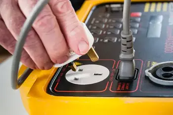
The Earth Leakage test places the MD from the earth ground pin of the DUT to the neutral side of the line (which is referenced to ground). Before running this check, confirming protective earth integrity with a ground tester ensures the reference path is valid for accurate measurements.
ENCLOSURE LEAKAGE TEST:
The Enclosure Leakage test places the MD from one or more points on a DUT’s chassis to the neutral side of the line.
PATIENT AUXILIARY LEAKAGE TEST:
The Patient Auxiliary Leakage test places the MD in between 2 different applied parts that come into contact with apatient’s body.
CONCLUSION
Although the Line Leakage test can seem somewhat confusing at times, it is an important test that should be given due consideration in any electrical safety testing routine. Technological advancements have made LLT much easier to perform and more manufacturers are performing LLT in both a lab and production environment. With some research and the right equipment, Line Leakage testing can be performed as quickly and easily as more common tests such as a Hipot or Ground Bond test. This means that the LLT can be added to a safety testing routine, without negatively impacting throughput and the addition of the LLT to any safety testing routine will help make electrical products safer and more reliable. This will save money in the long run.
From: Electrical Maintenance Handbook Vol. 10 - The Electricity Forum
Advantages To Instructor-Led Training – Instructor-Led Course, Customized Training, Multiple Locations, Economical, CEU Credits, Course Discounts.
Request For QuotationWhether you would prefer Live Online or In-Person instruction, our electrical training courses can be tailored to meet your company's specific requirements and delivered to your employees in one location or at various locations.