Ground Tester Section Criteria
Ground Tester Section Criteria is important to decide. The electrical grounding component of an electrical facility can be easily overlooked. It doesn’t appear to have an active role. It isn’t moving, doesn’t emit light or sound, or provide data. It’s largely out of sight. But the electrical ground is in fact dynamic. It gets challenged and stressed like any other part of the electrical system. It can deteriorate and lose effectiveness. It should be checked, tested, and maintained, just as visible, active equipment must be.
Factors that affect the Ground Tester Section Criteria include weather, corrosion, catastrophic events, soil properties, and the electrical plant itself. Weathering, especially the pressures caused by freezing and thawing, can break apart joints and welds and physically deteriorate a ground. Corrosion, promoted by electrical conductivity through moisture and dissolved salts in the soil, can eat away a grounding structure until virtually nothing remains below the surface. The massive energy of lightning strikes can cause the grounding structure to be sacrificed even while it is effectively diverting the strike from the electrical system. The basic condition of the soil itself can undergo long-term changes that may adversely affect electrical grounding capability. Surrounding industrial and residential expansion can lower the water table, placing a once-favorable ground in drier, less conductive soil.
And not to be overlooked are changes in the electrical demands of the facility itself. As sophisticated, sensitive electronic equipment is installed during the process of modernization, the original grounding requirement may no longer be adequate. The narrow voltage “windows” of computer and process control operations demand the maximum in ground efficiency if they are to function properly without noise interference. An older physical plant that was designed before electronics will most likely not meet this demand.
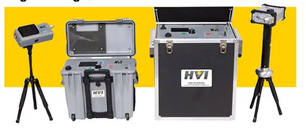
Evaluating the Ground Tester Section Criteria of a grounding electrode (the term includes rods, grids, ground beds, counterpoise systems, and similar variations) begins with the proper selection of a test instrument. The truly critical aspect of ground tester selection isn’t so much how to make the selection as it is simply to choose a ground tester in the first place! That is to say, the most common error is in the selection of a unit other than a ground tester to perform a ground tester’s function.
As the goal of evaluating Ground Tester Section Criteria is to measure ground resistance, it is reasoned, by a common application of what might be considered faulty logic, that any ohmmeter will do. Generic multimeters, VOMs, and insulation testers with continuity ranges are all frequently used. The consequences are lost time and the risk of incorrect or unreliable readings. Time spent traveling to a job site can be wasted when it is discovered that the test instrument is not capable of performing a required test or conforming to a mandated procedure. And measurements taken with a generic ohmmeter are subject to uncertainties that reduce their reliability to a matter of chance.
Generic ohmmeters are used to test ground electrodes by means of a method that is commonly referred to as a “Two- Point” or “Dead Earth” test. One lead of the tester is connected to the ground electrode being tested, and the other to a reference ground. The latter is most often the water-pipe system, but may also be a separately driven rod, metal fence post, or any convenient metallic connection to the soil. The resultant measurement is the series resistance of the entire loop, and its accuracy is contingent upon the reference ground (plus test leads) being of negligible resistance. The intervening soil is assumed to be contributing nearly all of the reading. The “two points” mentioned are the points of connection with the earth (electrode and reference ground), as distinguished from a Fall of Potential (three point) test and Wenner Method (four-point test). The term “dead earth” refers to the reference ground not being part of the electrical system.
There are three major limitations to this method:
- The assumption that the reference is of negligible resistance.
- The spacing of the contact points is arbitrary.
- Interference from voltage transients in the soil.
The IEEE, in its standard for ground resistance testing(#81) observes of the two-point method: “…This method is subject to large errors for low-valued driven grounds but is very useful and adequate where a ‘go, no-go’ type of test is all that is required.”
Use of a specialized ground tester readily overcomes these problems. Four-wire bridge measurement and dedicated test probes isolate the resistance of the ground under test as the only component of the reading. Separation of current and potential test circuits enables the operator to position the test probes outside of the electrical sphere of the tested ground, while movement of the potential probe in accordance with established procedures verifies that adequate spacing has been achieved. And the separate current circuit enables the use of an AC test signal that can be measured at frequencies distinct from those of any interfering transients. The use of a specific, dedicated ground tester enables the operator to control and monitor the conditions of the test in a way that no other type of instrumentation affords. The outcome of the test is reliable, repeatable, and free of chance. Test reports can be composed to assure clients that the measurement was made in accordance with a recognized, dependable method.
From: Power Quality & Electrical Grounding Handbook, Vol. 6 - The Electricity Forum
On-Site Training
Interested in cost effective, professional on-site electrical training?
We can present an Electrical Training Course to your electrical engineering and maintenance staff, on your premises, tailored to your specific equipment and requirements. Click on the link below to request a Free quotation.