
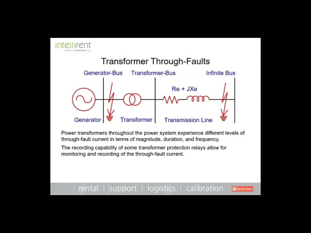
Transformer Protection methods vary widely, depending on the application and the importance of the electrical transformer. Transformers are protected mostly against internal faults and external overloads. The type of transformer protection used should minimize the time of disconnection for faults within the transformer and to reduce the risk of catastrophic failure to simplify eventual repair. Any extended operation of the transformer under abnormal condition such as faults or overloads compromises the life of the transformer, which means adequate protection should be provided for quicker isolation of the transformer under such conditions.
A transformer may be subjected to overcurrents ranging from just in excess of nameplate rating to as much as 10 or 20 times rating. Currents up to about twice rating normally result from overload conditions on the system, while higher currents are a consequence of system faults. When such overcurrents are of extended duration, they may produce either mechanical or thermal damage in a transformer, or possibly both. At current levels near the maximum design capability (worst-case through-fault), mechanical effects from electromagnetically generated forces are of primary concern. The pulsating forces tend to loosen the coils, conductors may be deformed or displaced, and insulation may be damaged. Lower levels of current principally produce thermal heating, with consequences as described later on loading practices. For all current levels, the extent of the damage is increased with time duration.
Power System Protection Courses
Short Circuit Study & Protective Device Coordination
Arc Flash Analysis/Study - IEEE 1584 Update
Protective Devices
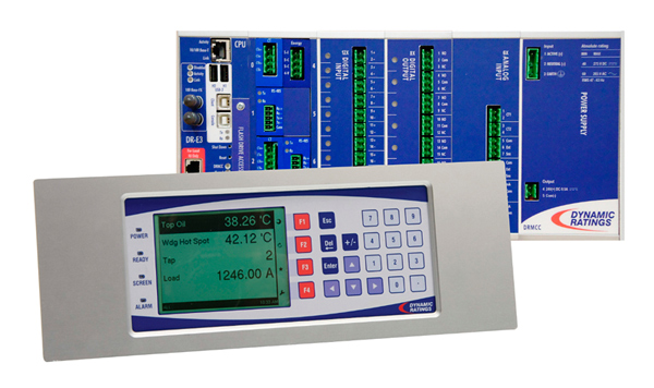
Whatever the cause, magnitude, or duration of the overcurrent, it is desirable that some component of the system recognize the abnormal condition and initiate action to protect the transformer. Fuses and protective relays are two forms of protective devices in common use. A fuse consists of a fusible conducting link which will be destroyed after it is subjected to an overcurrent for some period of time, thus opening the circuit. Typically, fuses are employed to protect distribution transformers and small power transformers up to 5000 to 10,000 kVA. Traditional relays are electromagnetic devices which operate on a 400 reduced current derived from a current transformer in the main transformer line to close or open control contacts, which can initiate the 200 operation of a circuit breaker in the transformer line circuit. Relays are used to protect all 100 medium and large power transformers.
Coordination
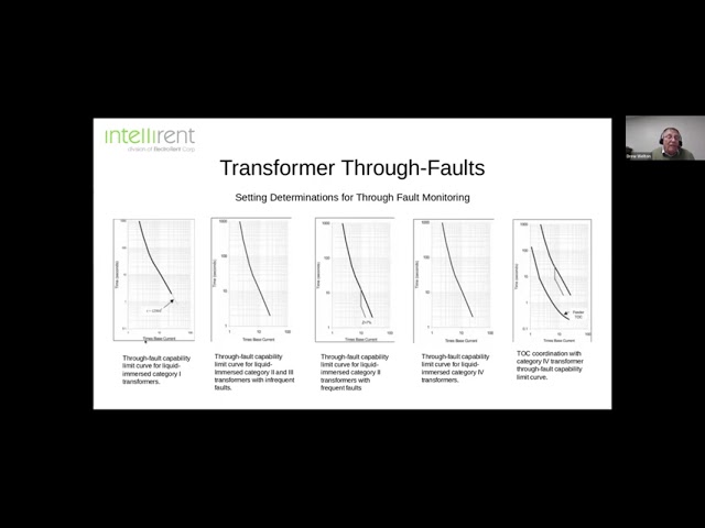
All protective devices, such as fuses and relays, have a defined operating characteristic in the current-time domain. This characteristic should be properly coordinated with the current-carrying capability of the transformer to avoid damage from prolonged overloads or through faults. Transformer capability is defined in general terms in a guide document, ANSI/IEEE C57.109, Transformer Through Fault Current Duration Guide. The format of the transformer capability curves is shown in Fig. 10-35. The solid curve, A, defines the thermal capability for all ratings, while the dashed curves, B (appropriate to the specific transformer impedance), define mechanical capability. For proper coordination on any power transformer, the protective-device characteristic should fall below both the mechanical and thermal portions of the transformer capability curve.
Fig. 1. Transformer through-fault protection curves
Read Other Electrical System Protection Articles
Maximum Fault Current Calculation


_1547716275.jpg)