Modern numerical relays have many new features that were not available in electromechanical or analog designs such as setting groups, programmable logic and adaptive schemes. Although these features make numerical relays very powerful, they also create a need for reviewing commissioning methods. It is common practice to make changes to commissioning tests and revised documentation of relay settings. There are very few standards covering commissioning, so most methods come from experience. There are many methods that give good results.
Commissioning protective relays requires three primary tasks the relay personnel should perform:
Calibrating the relays confirms that, when voltage and/or currents appear at the relay terminals, the relay will respond according to design and set-point. The functional test confirms that when the relay contacts close, the proper breakers trip or close according to the design. The functionality of all AC and DC schemes should also be checked.
To close the loop, in-service readings are taken as soon as the equipment is placed in service and has load current flowing. In-service readings confirm that, with a given load present, the proper voltages and currents appear at the relay terminals.
Calibrating relays and functional testing must be done before the equipment is put in service. In-service readings must be taken immediately after load is on the equipment.
The equipment is not released to the dispatcher or plant operator until the in-service readings are correct.
There are other commissioning tasks important to protective relays such as testing instrument transformers, meggering control cables, confirming transformer taps, and so on. However, this paper will concentrate on calibration, functional testing and in-service reading. These areas are most affected when using numerical relays.
Let's refer to electromechanical and solid-state relays as “traditional” and microprocessor based designs as “numerical”. Although there are significant differences in electromechanical and solid-state devices, the methods used for testing and commissioning are similar, whereas numerical relays must be approached differently.
COMMISSIONING TRADITIONAL RELAYS
Let’s discuss how we would commission this traditional relay. Relay calibration is performed using the manufacturer’s instruction manual and the relay setting sheets. In our simple overcurrent example, the setting sheet would include identifying information about the station name, the feeder number, and relay model numbers. The actual setting is: . CT ratio
This information will easily fit on one sheet of paper, and keeping copies of the setting in either hard copy or electronically is easy.
The settings are put on the relays by selecting taps, adjusting dials or setting switches.
Secondary current values are then injected into the relay using a test set. Pickup of the 50 and 51 elements is checked against the setting, and adjustments are made to bring the relay within calibration limits. Timing tests of the 51 element are also made to ensure the time dial and curve settings are correct. The output contacts are monitored during these tests with an ohmmeter or test set to indicate operation.
Functional Testing, also called trip checking, is another keystone activity of commissioning.
This is not the place to cut corners. Our intent is to confirm that the protection and controls work as intended and also that they have no unintended consequences.
Making checks to ensure the design works right is called a “positive” test. Making checks to see that the design doesn’t work incorrectly is called a “negative” test.
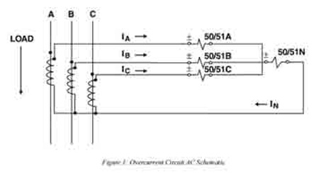
The phase overcurrent relays will trip the breaker directly. The ground relay has a cutout switch that must be closed to trip the breaker. Each overcurrent relay is operated one-at-a time to make certain each one works. The relay contact should be forced to close with the test set instead of applying a jumper across the contact.
Targets are confirmed after each trip. Open the ground cutout switch, then attempt to trip with the ground relay; the breaker should not trip. With the ground relay trip contact still closed, turn the ground cutout switch back on and confirm that the breaker trips. This proves the cutout switch prevented tripping and not something else. These are all “positive” tests.
From: Electrical Relays, Protection & Control Handbook, Vol 5, The Electricity Forum


_1547716275.jpg)