Electrical Protection
Protective Relay Testing: Verifying Protection Before It Matters
Download Our FREE Electrical Protection Handbook
Electrical Relays, Protection & Control Handbook Vol. 5
This more than 100 page handbook is an invaluable tool for the protection and control of your electrical systems.
In this edition, we delve into the latest advancements in relay technology, covering both conventional and digital protection relays, their applications, and the principles behind their operation. With a focus on practical strategies for system coordination, fault detection, and response, this volume provides a detailed understanding of how to design and implement effective protection schemes. Additionally, we explore the growing role of automation and smart control systems in enhancing system reliability, efficiency, and fault tolerance.
Throughout this handbook, you'll find a wealth of knowledge on key topics such as overcurrent protection, differential relays, distance protection, and fault analysis, with real-world case studies and troubleshooting advice to help you navigate complex electrical challenges. Volume 5 also addresses the integration of protection systems with modern communication networks, highlighting how technologies like IEC 61850 are transforming the way protection and control systems are configured and managed.
Whether you are an electrical engineer, technician, or systems operator, Electrical Relays, Protection & Control Handbook, Volume 5 provides you with the tools, best practices, and insights needed to optimize the protection and control of electrical systems, ensuring both safety and operational continuity in today's ever-evolving electrical landscape.
Latest Electrical Protection Articles
Improved Power System Reliability With Multifunction Relays
Feeder Protection Relay Decisions in Distribution Systems
How a Protective Relay Shapes Protection Outcomes
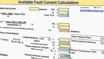
Maximum Fault Current Calculation Explained
Commissioning Numerical Relays Explained