Voltage Drop Calculator for Cable Sizing
By William Conklin, Associate Editor
Voltage Drop Calculator
Voltage Drop
--
% Drop
--
Voltage at Load
--
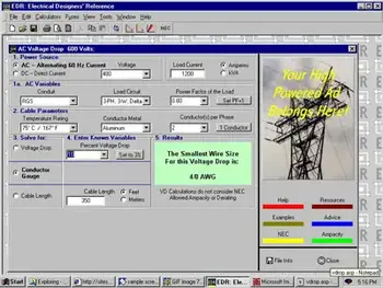
Voltage Drop Calculator Inputs and Outputs
Inputs: voltage, current, conductor length, material, wire size. Outputs: voltage drop, percentage drop, voltage at load.
Voltage Drop Calculator Use
Enter values and review results. Adjust conductor size or length if voltage drop is too high.

