What is a Watt? Electricity Explained
By William Conklin, Associate Editor
A watt is the SI unit of electrical power that measures the rate at which electrical energy is transferred or consumed.
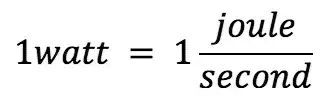
In electrical systems, power is measured as a rate rather than an accumulated quantity. While a watt measures power at a specific moment, the total amount of energy used over time is typically expressed in kilowatt-hours (kWh), which appear on electricity bills and energy meters. A watt is equivalent to one joule per second, making it a practical unit for relating electrical activity to real-world energy use across devices, circuits, and electrical systems.
Overview: What is a Watt?
In electrical systems, watts measure how much work electricity is doing at any given moment. Rather than measuring stored energy, wattage indicates the intensity of electrical activity and the degree to which a device or circuit is being loaded during operation.
A Watt provides a practical way to compare electrical equipment of all sizes, from small electronic components to large industrial machines. By expressing power as a rate, electricians and engineers can evaluate system capacity, balance loads, and ensure that conductors and protective devices are properly matched to real operating conditions. While watts describe instantaneous power, long-term energy usage is tracked using devices like a watt-hour meter, which records consumption over time.
Because wattage is directly tied to voltage and current, it sits at the center of electrical fundamentals. Since power increases with current, changes in current can significantly affect how many watts a device consumes under load.Any change in voltage or current affects a device's wattage, which is why power calculations are essential when designing circuits, selecting equipment, or managing energy use across buildings and the power grid. In practical installations, electricians often verify power levels using instruments such as wattmeters, which directly measure electrical power in operating systems.
Named after engineer James Watt, the unit remains a common reference point across electrical design, energy planning, and everyday appliance ratings, allowing power usage to be understood quickly and consistently. The relationship between watts, volts, and amperes is closely related to Ohm’s law, which helps explain how resistance influences power in real electrical circuits.
Power, Energy, and Electrical Flow
It is important to distinguish between power and energy. A watt measures power, which is the rate at which energy is used or produced. Energy, on the other hand, accounts for how long that power is applied. This is why utility bills are measured in kilowatt-hours rather than watts alone.
Electrical power can be calculated by multiplying voltage by current. When electrical current flows through a conductor or component, power is produced, and some of that power is inevitably converted into heat. Even highly efficient equipment releases heat because no electrical system operates at perfect efficiency.
Power does not appear only as heat. It can also take the form of light, motion, sound, or electromagnetic radiation. A light bulb converts electrical power into visible light and heat, while a motor converts electrical power into mechanical motion, with thermal losses. In AC systems, wattage must also be considered alongside power factor, since inefficient power use can increase current without delivering useful work.
Calculating Watts in Electrical Circuits
In electrical terms, a watt is calculated using a simple relationship between voltage and current:
W = V × A
This means that a device operating at 120 volts and drawing 10 amperes consumes 1,200 watts of power. If the voltage or current changes, the wattage changes accordingly. This relationship is fundamental to electrical design and is used to size conductors, select protective devices, and evaluate system loads.
For example, a small lamp operating at 3 volts and 0.1 amperes uses 0.3 watts of power. A household appliance operating at higher voltage and current will consume far more power, even if it runs for a shorter time. Because wattage depends directly on both voltage and current, understanding how voltage behaves in a circuit is essential when evaluating power demand and equipment ratings.
Understanding Power Levels and Prefixes
Electrical power is often expressed using metric prefixes to reflect scale. Milliwatts and microwatts are common in electronics, kilowatts are used for household and commercial equipment, and megawatts describe large-scale generation and industrial loads.
One kilowatt equals 1,000 watts, and one megawatt equals 1,000,000 watts. These prefixes make it easier to compare power levels across very different applications, from low-power sensors to power plants.
Why Watts Matter in Real-World Use
Watt ratings help determine how electrical systems are designed and how energy costs accumulate. Circuits must be sized to carry the expected wattage, and power supplies must be capable of delivering the required load without overheating or failure.
Understanding the watt also helps users make informed decisions about efficiency, energy consumption, and operating costs. Devices with lower wattage typically consume less energy over time, especially when used continuously.
Frequently Asked Questions
How does a watt relate to energy?
A watt measures how fast energy is being used or produced. One watt equals one joule per second, which describes the rate of energy flow rather than total energy consumed.
How is a watt different from a watt-hour?
A watt measures power, while a watt-hour measures energy over time. Using a 100-watt device for 10 hours results in 1,000 watt-hours of energy consumption.
What does a device’s watt rating mean?
The watt rating shows how much power a device draws during operation. Higher wattage generally means higher electrical demand and greater energy use over time.


How many watts do common appliances use?
Wattage varies widely. Laptops often use under 100 watts, while kitchen appliances and space heaters can draw over 1,000 watts depending on design and usage.
Related Articles

