Three Phase Electricity Explained


Three Phase Electricity

Three phase electricity delivers power using three alternating currents that are offset in phase. It provides consistent and efficient energy for industrial, commercial, and high-load applications, improving stability and reducing conductor size.


What is Three Phase Electricity?

Three phase electricity is a power system that uses three alternating currents, each offset by 120 degrees, to deliver constant power flow.

✅ Delivers more efficient and stable power than single-phase systems

✅ Ideal for large motors, commercial buildings, and industrial equipment

✅ Reduces conductor material and energy loss over long distances


Three phase voltage, frequency and number of wires

Three phase electricity is the dominant method of electrical power generation, transmission, and distribution across the industrialized world. Unlike single-phase systems, which rely on a single alternating current, three-phase systems use three separate currents, each 120 degrees out of phase with the others. This setup provides a consistent and balanced power flow, making it significantly more efficient for high-demand applications, such as motors, transformers, and large-scale infrastructure. Understanding the difference between alternating current and direct current is essential to grasp how three-phase systems deliver constant power using offset waveforms.


Understanding the Concept

At the heart of a three-phase system are three sinusoidal waveforms, evenly spaced to maintain a continuous flow of energy. When one phase reaches its peak, the others are in different parts of their cycle, ensuring that at any given moment, some power is being delivered. This creates what is known as constant power transfer, a major advantage over single-phase systems that experience power dips between cycles. Since three-phase systems rely heavily on accurate current flow measurement, it’s important to know what ammeters measure and how they help monitor system balance.

For industrial and commercial operations, this stability translates to increased energy efficiency, extended equipment lifespan, and reduced operating costs. Large electric motors, for example, run more smoothly on three-phase power, which avoids the surging and vibration commonly associated with single-phase inputs.


A Brief History

Three phase electricity wasn’t invented by a single person but emerged through the contributions of several pioneers in the late 19th century. Galileo Ferraris in Italy, Nikola Tesla in the United States, and Mikhail Dolivo-Dobrovolsky in Europe all played crucial roles in developing and refining the idea of three-phase alternating current. Tesla’s patents and Dolivo-Dobrovolsky’s practical systems laid the groundwork for what is now a global standard. Engineers use wattmeters to accurately measure real power in three-phase systems, while Watts Law helps calculate the relationships between voltage, current, and power.


Wye and Delta Configurations

Three-phase systems are typically wired in one of two configurations: the Wye (Y) or Delta (Δ) configuration. Each has specific advantages depending on the application:

  • In a Wye connection, each phase is tied to a central neutral point, allowing for multiple voltage levels within the same system. This is common in both commercial and residential applications, where both high and low voltages are required.

  • A Delta connection utilizes a closed loop with no neutral, a configuration commonly found in industrial setups. It delivers the same voltage between all phases and is ideal for running large motors without needing a neutral return path.

One of the most important relationships in these configurations is the √3 ratio between line voltage and phase voltage, a fundamental aspect that engineers use in calculating load, cable sizing, and protective device coordination.


Technical Benefits

Three-phase systems have built-in advantages that go beyond stability. Because the sum of the three phase currents is zero in a balanced load, a neutral wire is often unnecessary. This reduces the amount of conductor material needed, lowering costs and simplifying design. Additionally, three-phase motors naturally create a rotating magnetic field, eliminating the need for external circuitry to start or maintain rotation.

Another major benefit is that power output remains consistent. In single-phase systems, power drops to zero twice per cycle, but three-phase systems deliver non-pulsating power, which is especially important in sensitive or precision equipment. The function of a busbar is especially important in three-phase distribution panels, helping to manage multiple circuit connections efficiently.


Where and Why It’s Used

While most homes use single-phase electricity, three-phase is the standard in virtually all commercial and industrial environments. Factories, data centers, hospitals, and office buildings rely on it to power everything from HVAC systems and elevators to conveyor belts and industrial machines.

Three-phase is also common in electric vehicle (EV) charging stations and renewable energy systems, where efficient, high-capacity delivery is essential. If you're working with three-phase motors or transformers, knowing the role of a conductor and how electrical resistance affects current flow is fundamental to efficient design.

For sites that only have access to single-phase power, phase converters—whether rotary or digital—can simulate three-phase conditions, enabling them to operate three-phase equipment. This flexibility has made three-phase solutions accessible even in remote or rural areas. Three-phase systems often operate at medium voltage, especially in commercial settings, and their stability can reduce the risks of ground faults.


Voltage Levels and Color Codes

Depending on the region, the standard line and phase voltages vary. In North America, typical voltage values include 120/208 volts and 277/480 volts, whereas in Europe and much of Asia, 230/400 volts is more common. Wiring color codes also differ: red/yellow/blue in Europe, black/red/blue in North America, and other variations depending on the country's electrical code. These standards ensure safety, compatibility, and ease of troubleshooting.


The Global Standard for Power

Three-phase electricity is not just a technical solution; it is the foundation of modern electrical infrastructure. Its ability to deliver large amounts of power efficiently, safely, and reliably has made it the system of choice for more than a century. From powering the machines that build our world to the systems that keep us connected, three-phase electricity remains indispensable.


Related Articles


Related News

Thevenin's Theorem

Thevenin’s Theorem simplifies complex linear circuits into a single voltage source and series resistance, making circuit analysis easier for engineers. It helps calculate current, load behavior, and equivalent resistance in practical electrical systems.


What is Thevenin’s Theorem?

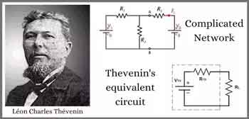
Thevenin’s Theorem is a method in circuit analysis that reduces any linear electrical network to an equivalent circuit with a voltage source (Vth) in series with a resistance (Rth).

✅ Simplifies circuit analysis for engineers and students

✅ Calculates load current and voltage with accuracy

✅ Models equivalent resistance for real-world applications

Thevenin’s Theorem allows any linear, two-terminal circuit to be represented by a single voltage source in series with a resistance.

  • Reduces complex circuits to a simple equivalent consisting of a voltage source and a resistor

  • Makes analyzing load response and network behavior straightforward, saving time and effort

  • Widely used for calculating current, voltage, or power across loads in electrical networks

To fully grasp why Thevenin’s Theorem matters, it helps to revisit the principles of basic electricity, where voltage, current, and resistance form the foundation of all circuit analysis.


Understanding Thevenin’s Theorem

Thevenin’s Theorem is a cornerstone of basic electrical engineering and circuit analysis. First introduced by French engineer Léon Charles Thévenin in the late 19th century, the theorem allows engineers and students alike to simplify a complex electrical network to a single voltage source (known as the Thevenin voltage, Vth) in series with a single resistor (known as the Thevenin resistance, Rth). This is particularly useful when analyzing how a circuit will behave when connected to different loads. Concepts such as Ohm’s Law and electrical resistance work in conjunction with Thevenin’s method, ensuring accurate load and network calculations.

Thevenin’s Theorem states that any linear electrical network can be simplified to an equivalent circuit consisting of a single voltage source in series with a resistance. By removing the load resistance, engineers can calculate the equivalent circuit voltage at the terminals, which represents how the circuit will behave when reconnected. This approach replaces multiple components and ideal voltage sources with one simplified model, making circuit analysis more efficient while preserving accuracy in predicting load behavior.


How Thevenin’s Theorem Works

According to Thevenin’s Theorem, no matter how complicated a linear circuit may be, with multiple sources and resistors, it can be replaced by an equivalent Thevenin circuit. This greatly simplifies the process when you’re only interested in the voltage, current, or power delivered to a specific part of the circuit. The steps typically followed when using Thevenin’s Theorem are:

  1. Identify the portion of the circuit for which you want to find the Thevenin equivalent (usually across two terminals where a load is or will be connected).

  2. Remove the load resistor and determine the open-circuit voltage across the terminals. This voltage is the Thevenin voltage (Vth).

  3. Calculate the Thevenin resistance (Rth) by deactivating all independent voltage sources (replace them with short circuits) and current sources (replace them with open circuits), then determining the resistance viewed from the terminals.

  4. Redraw the circuit as a single voltage source Vth in series with resistance Rth, with the load resistor reconnected.


Why Use Thevenin’s Theorem?

There are several reasons why Thevenin’s Theorem is so widely used in both academic and practical electrical engineering:

  • Simplification – Instead of solving a complex network repeatedly each time the load changes, engineers can just reconnect different loads to the Thevenin equivalent, saving time and reducing the potential for error.

  • Insight – By reducing a circuit to its essential characteristics, it’s easier to understand how changes will affect load voltage, current, or power.

  • Foundation for Further Analysis – Thevenin’s Theorem forms the basis for other network analysis techniques, such as Norton's Theorem, and is fundamental to understanding more advanced topics like maximum power transfer.


Example Application

Imagine a scenario where you need to analyze a circuit with multiple resistors and voltage sources connected in series, with a load resistor at the end. Without Thevenin’s Theorem, calculating the voltage across or current through the load each time you change its resistance would require solving complicated sets of equations. Thevenin’s Theorem allows you to do all the hard work once, finding Vth and Rth, and then quickly see how the load responds to different values.

Illustrative Case: A power supply circuit needs to be tested for its response to varying loads. Instead of recalculating the entire network for each load, the Thevenin equivalent makes these calculations swift and efficient. A deeper look at capacitance and inductance shows how energy storage elements influence circuit behavior when simplified through equivalent models.


Limitations and Conditions

While powerful, Thevenin’s Theorem has limitations:

  • It only applies to linear circuits, those with resistors, sources, and linear dependent sources.

  • It cannot directly simplify circuits containing nonlinear elements such as diodes or transistors in their nonlinear regions.

  • The theorem is most useful for “two-terminal” or “port” analysis; it doesn’t help as much with multiple output terminals simultaneously, though extensions exist.


Connections to Broader Electrical Concepts

Thevenin’s Theorem is closely related to other concepts, such as Norton’s Theorem, which prescribes an equivalent current source and parallel resistance. Both theorems are widely applied in real-world scenarios, including power distribution, signal analysis, and the design of electronic circuits. For example, it's relevant when considering how hydro rates impact load distribution in utility networks.

Thevenin’s Theorem is more than just a trick for simplifying homework—it is a core analytical tool that forms the backbone of practical circuit analysis. Whether you are a student learning circuit theory or an engineer designing power systems, understanding and applying Thevenin’s Theorem is essential.  Understanding current flow and the role of a conductor of electricity provides practical insight into why reducing networks to simple equivalents makes engineering analysis more efficient.


Related Articles


View more

Lenz's Law Explained

Lenz’s Law is a principle of electromagnetic induction stating that induced current flows in a direction that opposes the change in magnetic flux producing it. This rule ensures energy conservation and explains how circuits, coils, generators, and transformers behave in changing fields.


What is Lenz’s Law?

Lenz’s Law, rooted in Faraday’s Law of Induction, states that the direction of an induced current or electromotive force (emf) always opposes the change in magnetic flux that produced it. This principle safeguards conservation of energy in electromagnetic systems.

✅ Explains opposing force in induced current and magnetic fields

✅ Fundamental to understanding circuits, transformers, and generators

✅ Practical in energy conversion, electric motors, and induction device

Lenz's Law, named after the Russian physicist Heinrich Lenz (1804-1865), is a fundamental principle in electromagnetism. It states that the direction of the induced electromotive force (emf) in a closed conducting loop always opposes the change in magnetic flux that caused it. This means that the induced current creates a magnetic field that opposes the initial change in magnetic flux, following the principles of conservation of energy. A strong grounding in basic electricity concepts makes it easier to see why Lenz’s Law is central to modern circuit design.


Understanding Lenz's Law enables us to appreciate the science behind various everyday applications, including electric generators, motors, inductors, and transformers. By exploring the principles of Lenz's Law, we gain insight into the inner workings of the electromagnetic world that surrounds us. Engineers use this principle when designing three-phase electricity systems and 3-phase power networks to maintain energy balance.

Lenz's Law, named after the Russian physicist Heinrich Lenz (1804-1865), is a fundamental principle that governs electromagnetic induction. It states that the induced electromotive force (emf) in a closed conducting loop always opposes the change in magnetic flux that caused it. In simpler terms, the direction of the induced current creates a magnetic field that opposes the initial change in magnetic flux. 

Lenz's Law is a fundamental law of electromagnetism that states that the direction of an induced electromotive force (EMF) in a circuit is always such that it opposes the change that produced it. Mathematically, Lenz's Law can be expressed as:

EMF = -dΦ/dt

Where EMF is the electromotive force, Φ is the magnetic flux, and dt is the change in time. The negative sign in the equation indicates that the induced EMF is in the opposite direction to the change in flux.

Lenz's Law is closely related to Faraday's Law of electromagnetic induction, which states that a changing magnetic field induces an EMF in a circuit. Faraday's Law can be expressed mathematically as:

EMF = -dΦ/dt

where EMF is the electromotive force, Φ is the magnetic flux, and dt is the change in time.

Ampere's Law and the Biot-Savart Law are also related to Lenz's Law, as they describe the behaviour of electric and magnetic fields in the presence of currents and charges. Ampere's Law states that the magnetic field around a current-carrying wire is proportional to the current and the distance from the wire. The Biot-Savart Law describes the magnetic field produced by a current-carrying wire or a group of wires. Because Lenz’s Law governs the behavior of induced currents, it directly complements Ampere’s Law and the Biot-Savart Law in explaining magnetic fields.

Together, these laws provide a complete description of the behaviour of electric and magnetic fields in various situations. As a result, they are essential for understanding the operation of electric motors, generators, transformers, and other devices.

To better understand Lenz's Law, consider the scenario of a bar magnet moving toward a coil of wire. When the magnet moves closer to the coil, the number of magnetic field lines passing through the coil increases. According to Lenz's Law, the polarity of the induced emf in the coil is such that it opposes the increase in magnetic flux. This opposition creates an induced field that opposes the magnet's motion, ultimately slowing it down. Similarly, when the magnet is moved away from the coil, the induced emf opposes the decrease in magnetic flux, creating an induced field that tries to keep the magnet in place.

The induced field that opposes the change in magnetic flux follows the right-hand rule. If we hold our right hand around the coil such that our fingers point in the direction of the magnetic field lines, our thumb will point in the direction of the induced current. The direction of the induced current is such that it creates a magnetic field that opposes the change in the magnetic flux.

The pole of the magnet also plays a crucial role in Lenz's Law. When the magnet's north pole moves towards the coil, the induced current creates a magnetic field that opposes the north pole's approach. Conversely, when the magnet's south pole moves towards the coil, the induced current creates a magnetic field that opposes the south pole's approach. The direction of the induced current follows the right-hand rule, as we discussed earlier.

It is related to Faraday's Law of Electromagnetic Induction, which explains how a changing magnetic field can induce an electromotive force (emf) in a conductor. Faraday's Law mathematically describes the relationship between the induced electromotive force (emf) and the rate of change of magnetic flux. It follows Faraday's Law, as it governs the direction of the induced emf in response to the changing magnetic flux. To fully understand how electromagnetic induction works, it is helpful to see how Faraday’s discoveries laid the foundation for Lenz’s Law.

It is also related to the phenomenon of eddy currents. Eddy currents are loops of electric current induced within conductors by a changing magnetic field. The circulating flow of these currents generates their magnetic field, which opposes the initial magnetic field that created them. This effect is in line with Lenz's Law and has practical applications, such as in the braking systems of trains and induction cooktops.

Lenz's Law has numerous practical applications in our daily lives. For example, it plays a significant role in the design and function of electric generators, which convert mechanical energy into electrical energy. In a generator, a rotating coil experiences a changing magnetic field, resulting in the generation of an electromotive force (emf). The direction of this induced emf is determined by Lenz's Law, which ensures that the system conserves energy. Similarly, electric motors operate based on Lenz's Law. In an electric motor, the interaction between the magnetic fields and the induced electromotive force (emf) creates a torque that drives the motor. In transformers, including 3-phase padmounted transformers, Lenz’s Law explains why flux changes are controlled for efficiency and safety.

Lenz's Law is an essential concept in the design of inductors and transformers. Inductors are electronic components that store energy in their magnetic field when a current flows through them. They oppose any change in the current, following the principles of Lenz's Law. Transformers, which are used to transfer electrical energy between circuits, utilize the phenomenon of electromagnetic induction. By understanding it, engineers can design transformers.


Related Articles


View more

Biot Savart Law Explained

The Biot Savart Law describes how electric current generates magnetic fields, showing the relationship between current, distance, and field intensity. It is a key principle in physics, electromagnetism, and electrical engineering used to calculate magnetic effects in circuits.


What is Biot Savart Law?

The Biot Savart Law is a fundamental principle in electromagnetism that quantifies the magnetic field generated by an electric current.

✅ Relates magnetic field strength to current magnitude and distance.

✅ Provides a mathematical basis for calculating magnetic fields in circuits.

✅ Essential for understanding electromagnetism, physics, and engineering design.


Biot Savart Law and the study of electromagnetism have always been a fascinating field of science that deals with the interaction between electric and magnetic fields. One of the cornerstones in this domain is this law, named after the French scientists Jean-Baptiste Biot and Félix Savart. This law plays a vital role in understanding the behaviour of magnetic fields produced by electrical currents. The relationship between electricity and magnetism is at the heart of the Biot Savart Law, showing how moving charges generate magnetic effects.

Delving deeper into this fascinating concept, Biot Savart Law describes the magnetic field generated by a tiny current flowing through a conductor. The law states that the magnetic field at a point is directly proportional to the current and inversely proportional to the square of the distance between the point and the current-carrying conductor. Furthermore, the magnetic field's direction is perpendicular to the plane formed by the unit vector and the straight wire carrying the current. When studying current flow, it helps to compare this law with Ampere’s Law, which is often applied to symmetrical conductors and steady-state conditions.


Biot Savart Law Explained

It is a fundamental principle in electromagnetism that describes the magnetic field produced by a steady electric current. It is named after French physicists Jean-Baptiste Biot and Félix Savart, who formulated the law in 1820. It provides a means to calculate the magnetic field at any point in space due to a specific current distribution.

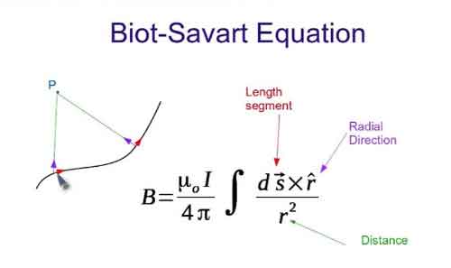
In mathematical terms, the Biot Savart Law can be expressed as:

dB = (μ₀ / 4π) * (Idl × r̂) / r²

Here,

  • dB represents the tiny magnetic field vector produced by an infinitesimal current element (Idl),

  • μ₀ is the permeability of free space (a constant with a value of 4π × 10^(-7) Tm/A),

  • I is the current flowing through the current element,

  • dl is the infinitesimal length vector of the current element,

  • r is the distance between the current element and the point in space where the magnetic field is being calculated,

  • r̂ is the unit vector pointing from the current element to the point of interest.

The Biot Savart Law states that the magnetic field produced by a small segment of a current-carrying conductor is proportional to the current, inversely proportional to the square of the distance from the point of interest, and depends on the angle between the current segment and the line connecting the segment to the point of interest.

To find the total magnetic field at a point in space due to an entire current distribution, you need to integrate the magnetic field contributions from each infinitesimal current element over the entire current-carrying conductor:

B = ∫dB

The Biot Savart Law is particularly useful for calculating the magnetic field in cases with complex current configurations or where symmetry is not apparent. In addition, it is often applied in situations where Ampere's Law would be difficult or impossible to use. Common applications include calculating magnetic fields due to straight wires, loops, and solenoids. A foundation in basic electricity concepts makes it easier to understand how current elements combine to produce magnetic fields.


Maxwell's Equations

One might wonder about the relationship between the Biot Savart Law and Maxwell's Equations, a set of fundamental equations that govern the behaviour of electric and magnetic fields. It can be derived from Maxwell's Equations, specifically Ampere's Law, which establishes a connection between an electric current and the magnetic field it generates.

While the Biot Savart Law and Ampere's Law address magnetic fields, their focus and applicability differ. For example, the Biot Savart Law is more useful for calculating magnetic fields due to current loops or irregular current-carrying conductors. In contrast, Ampere's Law best suits symmetrical geometries and steady-state currents.

The practical applications of the Biot Savart Law are abundant, ranging from designing and analyzing electromagnets and generators to determining the magnetic moment of a current loop, an essential parameter in magnetostatics. The law has also significantly advanced technologies such as magnetic resonance imaging (MRI), particle accelerators, and magnetic storage devices.

The versatility of the Biot Savart Law is exemplified by its ability to calculate magnetic fields of various geometries. From a straight wire or a solenoid to more complex configurations, such as toroidal or saddle-shaped coils, this law is a reliable tool for understanding the behaviour of magnetic fields in various scenarios.

Delving into the connections between different laws, the relationship between the Biot Savart Law and Faraday's Law is quite intriguing. While the Biot Savart Law is concerned with the magnetic field generated by a current, Faraday's Law deals with the electromotive force (EMF) induced in a conductor due to a changing magnetic field. Together, these laws form the basis of electromagnetic induction, which underpins the functioning of electric generators, transformers, and inductors.

The study of electromagnetism would only be complete by touching upon the concept of electric fields. Like magnetic fields, electric fields are fundamental aspects of electromagnetism, originating from electric charges. Coulomb's Law governs the interaction between electric charges, drawing parallels with the Biot Savart Law, which deals with magnetic fields generated by electric currents.

In the realm of vector calculus, the Biot Savart Law uses the cross product and the dot product to define the magnitude and direction of the magnetic field. These mathematical tools enable scientists and engineers to model and analyze the behaviour of magnetic fields in various applications.

One of the key parameters in the Biot Savart Law is the permeability of free space, denoted by the symbol μ₀. This constant defines the ease with which a magnetic field can permeate a vacuum and is crucial in determining the strength and range of the magnetic field generated by a current.

It is an essential concept in the study of electromagnetism. It provides a foundation for understanding magnetic fields generated by electric currents and connects with other fundamental laws, such as Ampere's Law, Faraday's Law, and Coulomb's Law. Moreover, the diverse applications of the Biot Savart Law, ranging from designing electromagnets to analyzing complex magnetic field geometries, showcase its versatility and importance.

As we continue to explore the world of electromagnetism, the Biot Savart Law will remain a crucial tool in our arsenal. Through rigorous research and innovative technologies, scientists and engineers will continue to unlock the mysteries of electric and magnetic fields, ultimately leading to groundbreaking discoveries and advancements that have the potential to transform our world.

From powering our homes with electricity to enabling cutting-edge technologies like MRI machines and particle accelerators, it plays a central role in shaping the science and engineering landscape. As we progress into the future, the Biot Savart law will undoubtedly continue to serve as a beacon of knowledge and understanding in the ever-evolving realm of electromagnetism. For a broader perspective on how energy sources shape our electrical systems, exploring alternative electricity provides useful context.


Related Articles


View more

Electricity Production

Electricity production converts primary energy into power via thermal, hydro, wind, and solar systems, optimizing efficiency, capacity factor, grid stability, transmission reliability, and emissions through turbines, generators, inverters, and advanced SCADA control.


What Is Electricity Production?

Electricity production converts energy to electric power, prioritizing efficiency, safety, and grid reliability.

✅ Conversion via turbines, generators, inverters, and transformers

✅ Control with SCADA, protective relays, and load-frequency regulation

✅ Optimization of efficiency, capacity factor, and emissions


Electricity Production continues to grow around the world, from a variety of energy power sources. In terms of world electricity generation, the US Department of Energy predicts advances strongly from 2004 to 2030. Global production increases by 2.4 percent per year over the projection period, from 16,424 billion kilowatthours in 2004 to 30,364 billion kilowatthours in 2030. Much of the growth in electric power demand is projected for nations outside the OECD. Although the non-OECD nations consumed 26 percent less electricity than the OECD nations in 2004, total generation in the non-OECD region in 2030 is projected to exceed generation in the OECD by 30 per cent. For context, the International Energy Outlook provides a concise overview of electricity generation trends worldwide today.

Total electricity demand in the non-OECD nations is expected to grow from 2004 to 2030 at an annual rate that is nearly triple the rate of growth for electricity demand in the OECD. The difference reflects the relative maturity of electricity infrastructure in the more developed OECD region, as well as the expectation that populations in the OECD countries generally will grow slowly or decline over the next 25 years. In addition, fast-paced growth in the developing non-OECD economies translates to rising standards of living and robust growth in consumer demand for lighting and appliances. Total electricity generation in the non-OECD region increases by an average of 3.5 percent per year in the IEO2007 reference case, as compared with a projected annual growth rate for OECD electricity generation that averages 1.3 per cent per year from 2004 to 2030. Among the energy end-use sectors, the most rapid growth in total world demand for electricity is projected for the buildings (residential and commercial) sectors.

Understanding the diversity of sources of electricity helps explain regional growth patterns in demand.

In Power plants, electricity Production involves the generation or creation of electric power, using rotating turbines attached to an energy generator. This mechanical manufacturing of electricity produces most commercially available electricity. Turbines are driven by a fluid which acts as an intermediate energy carrier. The fluids typically used are:

For readers new to plant design, this primer on how electricity is generated clarifies the roles of turbines, generators, and working fluids.

  • steam - Water is boiled by nuclear fission or the burning of fossil fuels (coal, natural gas, or petroleum). Some newer plants use the sun as the heat source: solar parabolic troughs and solar power towers concentrate sunlight to heat a heat transfer fluid, which is then used to produce steam. Another renewable source of heat used to drive a turbine is Geothermal power. Either steam under pressure emerges from the ground and drives a turbine or hot water evaporates a low boiling liquid to create vapour to drive a turbine.
  • water - Turbine blades are acted upon by flowing water, produced by hydroelectric dams or tidal forces,
  • wind - Most wind turbines generate electricity from naturally occurring wind. Solar updraft towers use wind that is artificially produced inside the chimney by heating it with sunlight.
  • hot gases - Turbines are driven directly by gases produced by the combustion of natural gas or oil. Combined cycle gas turbine plants are driven by both steam and gas. They generate power by burning natural gas in a gas turbine and use residual heat to generate additional electricity generation from steam. These plants offer efficiencies of up to 60%.

Hydropower and tidal technologies illustrate how water-based electricity remains a cornerstone in many regions.

Various other technologies have been studied and developed for power generation. Solid-state generation (without moving parts) is of particular interest in portable applications. This area is largely dominated by thermoelectric (TE) devices, though thermionic (TI) and thermophotovoltaic (TPV) systems have been developed as well. Typically, TE devices are used at lower temperatures than TI and TPV systems. Piezoelectric devices are used for power generation from mechanical strain, particularly in power harvesting. Betavoltaics are another type of solid-state power generator which produces electricity from radioactive decay. Beyond conventional turbines, a range of alternative electricity options are being explored for niche and distributed applications.

Fluid-based magnetohydrodynamic (MHD) electricity generation has been studied as a method for extracting electrical power from nuclear reactors and also from more conventional fuel combustion systems. These advanced concepts broaden our understanding of how we generate electricity under extreme conditions.

Electrochemical is also important in portable and mobile applications. Currently, most electrochemical power comes from closed electrochemical cells ("batteries"), which are arguably utilized more as storage systems than generation systems, but open electrochemical systems, known as fuel cells, have been undergoing a great deal of research and development in the last few years. Fuel cells can be used to extract power either from natural fuels or from synthesized fuels (mainly electrolytic hydrogen) and so can be viewed as either generation systems or storage systems depending on their use. In many systems the electricity generator ultimately interfaces with inverters and controls for grid integration.


Related Articles

View more

Voltage Drop Formula

The voltage drop formula is V = I × R, where V represents the voltage drop, I represents the current in amperes, and R represents the resistance in ohms. It calculates the amount of voltage lost through a conductor and is essential for designing safe and efficient electrical systems.


What is Voltage Drop Formula?

A voltage drop formula can help you manually calculate the voltage drop in cables under full load in branch circuits. It does not matter if you are working with copper or aluminum conductors. To accurately calculate the voltage drop for a given cable size, length, and current, you need to know the resistance of the type of cable you’re using. 

✅ V = I × R for DC circuits

✅ Accounts for impedance in AC circuits

✅ Helps ensure safe, efficient electrical design

Use our voltage drop calculator to quickly determine wire size, conductor efficiency, and line loss for safer, more reliable electrical installations.


Power Quality Analysis Training

Power Factor Training

Request a Free Power Quality Training Quotation

To determine voltage drop in an electrical system, engineers and electricians use a standard formula that accounts for conductor resistance, current, and circuit length. The National Electrical Code (NEC) provides guidelines for the maximum voltage drop allowed in various installations to ensure efficiency and safety. For both single-phase and three-phase circuits, excessive voltage drop can lead to poor equipment performance and energy loss. To simplify calculations, a voltage drop calculator can quickly assess whether a circuit meets NEC recommendations and optimize conductor sizing accordingly. You can learn more about how electrical resistance affects circuits in our detailed voltage drop guide, which explains causes, calculations, and solutions for safe, efficient power distribution.


DC / single phase calculation

The voltage drop V in volts (V) is equal to the wire current I in amps (A) times 2 times one way wire size length L in feet (ft) times the wire resistance per 1000 feet R in ohms (Ω/kft) divided by 1000:


Vdrop (V) = Iwire (A) × Rwire(Ω)

Iwire (A) × (2 × L(ft) × Rwire(Ω/kft) / 1000(ft/kft))


The voltage drop V in volts (V) is equal to the wire current I in amps (A) times 2 times one way wire length L in meters (m) times the wire resistance per 1000 meters R in ohms (Ω/km) divided by 1000:


Vdrop (V) = Iwire (A) × Rwire(Ω)

Iwire (A) × (2 × L(m) × Rwire (Ω/km) / 1000(m/km))


3 phase calculation

The line-to-line voltage drop V in volts (V) is equal to the square root of 3 times the wire current I in amps (A) times one-way wire length L in feet (ft) times the wire resistance per 1000 feet R in ohms (Ω/kft) divided by 1000:


Vdrop (V) = √3 × Iwire (A) × Rwire (Ω)

= 1.732 × Iwire (A) × (L(ft) × Rwire (Ω/kft) / 1000(ft/kft))


The line-to-line voltage drop V in volts (V) is equal to the square root of 3 times the wire current I in amps (A) times one-way wire length L in meters (m) times the wire resistance per 1000 meters R in ohms (Ω/km) divided by 1000:


Vdrop (V) = √3 × Iwire (A) × Rwire (Ω)

= 1.732 × Iwire (A) × (L(m) × Rwire (Ω/km) / 1000(m/km))


Wire diameter calculations

The n gauge wire diameter, dn in inches (in), is equal to 0.005in times 92 raised to the power of 36 minus gauge number n, divided by 39:


dn (in) = 0.005 in × 92(36-n)/39


The n gauge wire diameter dn in millimetres (mm) is equal to 0.127mm times 92 raised to the power of 36 minus gauge number n, divided by 39:


dn (mm) = 0.127 mm × 92(36-n)/39


Wire cross-sectional area calculations

The n gauge wire's cross-sectional area An in kilo-circular mils (kcmil) is equal to 1000 times the square wire diameter d in inches (in):


An (kcmil) = 1000×dn2 = 0.025 in2 × 92(36-n)/19.5


The n gauge wire's cross-sectional area An in square inches (in2), is equal to pi divided by 4 times the square wire diameter d in inches (in):


An (in2) = (π/4)×dn2 = 0.000019635 in2 × 92(36-n)/19.5


The n gauge wire's cross-sectional area, An, in square millimetres (mm2), is equal to pi divided by 4 times the square wire diameter d in millimetres (mm):


An (mm2) = (π/4)×dn2 = 0.012668 mm2 × 92(36-n)/19.5


Wire resistance calculations

The n gauge wire resistance R in ohms per kilofeet (Ω/kft) is equal to 0.3048×1000000000 times the wire's resistivity ρ in ohm-meters (Ω·m) divided by 25.42 times the cross-sectional area An in square inches (in2):


R(Ω/kft) = 0.3048 × 10⁹ × ρ(Ω·m) / (25.42 × An (in2))


The n gauge wire resistance R in ohms per kilometre (Ω/km) is equal to 1000000000 times the wire's resistivity ρ in ohm-meters (Ω·m) divided by the cross-sectional area An in square millimetres (mm2):


R(Ω/km) = 109 × ρ(Ω·m) / An (mm2)


Related Pages


View more

Power Factor Explained

Electrical systems depend on efficiency to operate safely and cost-effectively. One key indicator of that efficiency is power factor, which measures how effectively electrical energy is converted into useful work.

Power Quality Analysis Training

Power Factor Training

Request a Free Power Quality Training Quotation

Poor performance in this area leads to wasted energy, increased utility costs, and potential system stress. Managing it correctly can significantly improve overall reliability and lower expenses. To understand the foundation, see our detailed overview on what is power factor.


What is Power Factor?

In an AC circuit, managing efficiency often involves addressing issues caused by poor power factor. One common solution is to install capacitor banks, which help counteract the effects of inductive loads and improve the electrical system's power factor. However, when too much capacitance is introduced, it can result in a leading power factor, which may also create complications. Equipment that generates strong magnetic fields, such as motors and transformers, often disrupts the balance between real and apparent energy, reducing the ratio of power to apparent. Modern switched-mode supplies complicate matters further by introducing harmonic distortion into the energy supply, making it even more essential to monitor and correct the system regularly.


The Power Triangle visually represents the relationship between real power (kW), reactive power (kVAR), and apparent power (kVA) in an AC system. It highlights how a lower reactive component improves the overall system efficiency. In an AC circuit, real power (kW) performs useful work, reactive power (kVAR) supports magnetic fields, and apparent power (kVA) is the vector sum of the two.


How to Measure and Calculate Power Factor

Determining your system's performance begins with accurate measurement. Professionals use methods that involve real and apparent energy values, based on voltage and current readings.

To learn step-by-step techniques, visit our guide on how to calculate power factor. For the precise mathematical method, review the power factor formula.

You can also explore practical methods for finding power factor, which include using wattmeters, ammeters, and other field instruments.


Essential Tools for Performance Analysis

Accurately monitoring load conditions requires specialized equipment. Depending on the system's complexity, technicians may use portable meters, online analyzers, or built-in monitoring tools.

If you need a quick starting point, our power factor calculator simplifies the process.

For more detailed measurements, explore the capabilities of a power factor meter, designed for professional-grade accuracy.


Common Challenges in Electrical Systems

System inefficiencies often result from loads that are inductive or capacitive, creating phase shifts between voltage and current.

Inductive loads typically cause a lagging power factor, a frequent issue in industrial environments.

If you're dealing with capacitive loads or comparing system behaviors, you’ll find insights in leading vs lagging power factor.

Addressing these challenges early improves operational stability and reduces financial penalties from utilities.


Practical Methods to Improve Efficiency

Once a system's weaknesses are identified, targeted improvements can restore optimal conditions. Correction involves devices that realign the energy usage balance.

For an overview of different strategies, see power factor correction.

Installing a power factor correction capacitor is often the most straightforward method for load balancing.

For more dynamic systems, using an automatic power factor controller ensures continuous adjustments based on varying demands.


Why Unity Is the Ideal Goal

Achieving a unity rating, or a value of 1.0, means that all supplied energy is used effectively without waste.
Maintaining this condition ensures maximum cost savings, better equipment lifespan, and compliance with utility standards.

Discover the benefits and techniques by visiting unity power factor.


Measure, Monitor, and Manage for Long-Term Benefits

Improving the performance of your electrical system starts with regular monitoring, accurate measurement, and appropriate corrective action.
Whether you are troubleshooting existing problems or designing new systems, using the right tools and knowledge will keep operations running at peak power factor.


FAQ: Power Factor Questions


What causes a poor power factor?

Poor load balancing is typically caused by inductive loads like motors, transformers, and fluorescent lighting. These devices create magnetic fields that delay current flow, leading to a lagging power factor and wasted energy.


How much can a facility save by improving its power factor?

Improving system performance can reduce utility demand charges by 20% to 50% in some cases. It also decreases line losses, enhances system capacity, and extends equipment life, leading to significant operational savings.


What penalties apply for poor power factor?

Many utilities impose financial penalties if a facility’s reactive energy drops below a set threshold, often around 0.90. These charges can add thousands of dollars per year to an electric bill, making correction measures highly cost-effective.


What is a good power factor rating?

A good rating is typically above 0.95. The closer it is to 1.0, the more efficiently the system operates.


How often should I check my system's power factor?

It’s best to monitor it monthly, especially if your facility has changing load profiles throughout the year.


Can low power factor damage equipment?

While it may not cause direct damage, poor performance increases heating and losses, leading to premature wear and higher energy bills.


Are capacitors the only way to improve power factor?

No. Besides capacitors, active filters and automated correction devices like automatic power factor controllers offer flexible solutions.


What industries are most affected by poor load performance?

Industrial manufacturing, commercial buildings with heavy HVAC systems, and water treatment facilities are commonly impacted.


Related Articles


View more

Sign Up for Electricity Forum’s Newsletter

Stay informed with our FREE Newsletter — get the latest news, breakthrough technologies, and expert insights, delivered straight to your inbox.

Electricity Today T&D Magazine Subscribe for FREE

Stay informed with the latest T&D policies and technologies.
  • Timely insights from industry experts
  • Practical solutions T&D engineers
  • Free access to every issue

Live Online & In-person Group Training

Advantages To Instructor-Led Training – Instructor-Led Course, Customized Training, Multiple Locations, Economical, CEU Credits, Course Discounts.

Request For Quotation

Whether you would prefer Live Online or In-Person instruction, our electrical training courses can be tailored to meet your company's specific requirements and delivered to your employees in one location or at various locations.