Definition of a Rectifier

By R.W. Hurst, Editor


Definition of a rectifier explains AC to DC conversion using diodes, bridge or full-wave circuits, filters, and regulators to supply stable DC, reduce ripple, and power electronics, chargers, and DC motor drives.


What Is the Definition of a Rectifier?

An explanation of devices that convert AC to DC using diodes and filtering to deliver regulated, low-ripple DC power.

✅ Converts alternating current to direct current via diodes

✅ Topologies: half-wave, full-wave, bridge rectifier

✅ Uses filters and regulators to minimize ripple and stabilize DC


Understanding the definition of a rectifier is fundamental to grasping the complexities of power electronics and electrical engineering. Rectifiers are pivotal in converting AC power to DC power, a critical process for operating numerous electronic devices. By delving into the intricacies of half-wave, full-wave, and bridge rectifiers, as well as the silicon-controlled rectifier, it becomes clear that these devices are crucial in shaping the modern world of electronics. For readers new to the basics, an overview of the difference between AC and DC can clarify foundational concepts.


In electrical engineering, the definition encompasses a vital device that plays a crucial role in converting alternating current (AC) into direct current (DC). It  is an essential component in power electronics. It facilitates the conversion of AC power, commonly used in households and businesses, to DC power that electronic devices rely on. To contextualize this conversion, understanding alternating current behavior in typical distribution systems explains the need for rectification.

They come in various forms, such as diodes, mercury arc valves, and silicon-controlled rectifiers (SCRs). A diode, the most basic rectifying component, allows current to flow in only one direction. This feature helps convert AC power, which alternates direction, to DC power that flows in a single, continuous direction. For measurement and notation conventions, see how DC current is defined and applied in circuit analysis.

AC to DC conversion regulates voltage to create a steady and reliable energy supply. Throughout this conversion, rectifiers often assume different configurations depending on the specific application or requirement. Two popular configurations are the half-wave rectifier and the full-wave rectifier. Downstream stabilization is often handled by a voltage regulator that smooths residual ripple and safeguards loads.

A half-wave type allows only one half of the AC waveform to pass through while blocking the other half. This type is relatively simple and cost-effective but has a few downsides, such as lower efficiency and increased ripple voltage. Ripple voltage refers to the residual periodic variation of the DC output voltage. The result is an unsteady DC output, which might be undesirable in certain applications.

On the other hand, the full-wave type allows both halves of the AC waveform to pass through, effectively doubling the output frequency and reducing the ripple voltage. This configuration improves efficiency and provides a smoother, more consistent DC output voltage. The full-wave type has two primary forms: the center-tap configuration and the bridge rectifier.

The bridge rectifier is a highly efficient configuration that uses four diodes in a specific arrangement. This configuration eliminates the need for a center-tapped transformer, a key component in center-tap full-wave rectifiers, thus reducing overall size and cost. In addition, the bridge rectifier provides better voltage regulation and reduced harmonic distortion, making it ideal for various applications. For consistent terminology across datasheets, reviewing key electricity terms can prevent misinterpretation during design.

They serve numerous purposes in various fields. For instance, they are used in power supply circuits of electronic devices, battery chargers, and welding equipment. In addition, they help in voltage regulation for DC power supplies and extract radio signals from transmitted modulated signals. Many of these uses depend on stable direct current characteristics to ensure predictable device behavior.

Silicon-controlled rectifiers (SCRs) represent a more advanced type of rectifier. As silicon-based semiconductor switches, SCRs can control large amounts of current with a small input signal. This ability to manage current flow in a controlled manner sets SCRs apart from regular rectifiers, like diodes. As a result, SCRs are often used in power control applications, such as motor speed controllers, light dimmers, and temperature regulators.

Understanding how rectifiers play a pivotal role in industries and everyday applications is essential. One such application is in electric vehicles (EVs), where rectifiers contribute to charging systems by converting AC power from the grid to DC power for charging the battery. Additionally, they are utilized in renewable energy systems, like solar power and wind power, to convert the harvested energy into a stable and usable form for various applications. At a broader level, a concise electricity definition helps frame how conversion stages integrate with generation, storage, and loads.

Another application is in telecommunications equipment, where they help maintain a continuous and stable power supply. In the aviation and marine industries, rectifiers ensure sensitive equipment operates with minimal interference from fluctuating power sources. Moreover, they are employed in power supply units of medical devices, computers, and other critical equipment that demand stable power supplies.


How does it work in AC to DC conversion?

Its primary function is to convert AC voltage, which periodically reverses direction, into DC voltage, which flows in one direction. Its simplest form it consists of a diode, which allows current to pass in only one direction. When connected to an AC power source, the diode rectifies the current by blocking the negative half-cycles of the AC waveform. More advanced configurations, like full-wave rectifiers and bridge rectifiers, rectify both the positive and negative half-cycles, increasing efficiency and providing a smoother output.


What are the differences between half-wave and full-wave rectifiers?

The key difference between half-wave and full-wave rectifiers lies in their efficiency and output. A half-wave type only allows one-half of the AC waveform to pass through, blocking the other half. As a result, it has lower efficiency, increased ripple voltage, and produces an unsteady DC output.

On the other hand, a full-wave type allows both halves of the AC waveform to pass through, leading to increased efficiency and reduced ripple voltage. In addition, the full-wave type produces a smoother, more consistent DC output voltage, making it more suitable for applications that require a stable power supply. The full-wave type can be implemented using a center-tap or bridge rectifier configuration.


Related Articles

Related News

Ampere to Ampere Hour Calculator Explained

An ampere to ampere hour calculator converts electric current (amps) to electric charge (Ah) based on time. Multiply current by time in hours to get ampere hours. It's useful for battery capacity, energy storage, and electrical system design.


What is "Ampere to Ampere Hour Calculator"?

An ampere to ampere hour calculator helps convert current flow over time into stored electrical charge.

✅ Multiply current (A) by time (h) to calculate charge (Ah)
✅ Useful for battery sizing and energy storage systems
✅ Supports electrical load and backup power planning


The Ampere to Ampere-Hour Calculator is a useful tool that allows users to estimate the capacity of a battery by converting the current supplied by an electrical device into ampere-hours (Ah). This calculation is particularly important when working with batteries, as it helps determine how long a battery can power a device based on the current it supplies and the device's usage duration. By using this calculator, you can easily convert amps to Ah and estimate the run-time for a specific battery. Understanding how voltage affects battery performance is key, and our voltage guide explains the role voltage plays in ampere-hour calculations. When calculating ampere-hours, it's important to account for voltage drop across conductors, especially in longer circuits. Use our voltage drop calculator to estimate losses and adjust your amp-hour estimations more accurately.


Frequently Asked Questions


What is an Ampere to Ampere Hour calculator, and how does it work?

This calculator helps convert the current, measured in amperes, into Ah capacity, which indicates how long a battery can supply a given current. For instance, a 100ah battery will deliver 100 ampere-hours of charge, meaning it can supply 1 ampere of current for 100 hours, or 10 amperes for 10 hours. To calculate Ah, the formula involves multiplying the current (in amperes) by the time in hours. For example, if a device draws 5 amperes for 20 hours, the result would be 100 ampere-hours. Learn how a watthour meter measures energy over time, complementing ampere-hour readings in power systems.


How do you convert amperes to ampere-hours using a calculator?

To convert amps to Ah, simply multiply the number of amperes by the number of hours the current is expected to flow. This step-by-step method is straightforward:

Ampere Hour (Ah) = Amperes (A) × Time (hours)

For example, a device drawing 5 amps for 10 hours would result in a consumption of 50 Ah. In practical applications, a 100ah battery could theoretically supply 5 amps for 20 hours before running out of charge. By following these steps, users can easily convert Ah to ensure they select the right battery for their needs. A basic understanding of watts law helps you relate amps, volts, and watts to better interpret your battery’s output.


Why is converting amperes to ampere-hours important for battery capacity calculation?

Knowing how to convert amperes to Ah is crucial in determining the capacity of a battery. It enables users to estimate the battery life of a connected device based on its current draw. This information is crucial for selecting the appropriate battery type for various applications, including powering electronic devices, off-grid systems, and backup power sources. A 100 Ah battery might be suitable for low-power consumption devices, while larger systems might require batteries with higher capacities. Knowing what ammeters measure can help you determine current flow before calculating ampere-hours.


What factors should be considered when using an Ampere to Ampere Hour calculator?

When using an Ampere to Ampere Hour Calculator, several factors can affect the accuracy of the results. These include the hour rating of the battery, which defines its capacity over a specific time period, as well as the efficiency of the battery, which can vary depending on the battery type. Additionally, environmental conditions, such as temperature, may affect the battery’s performance. It is also important to avoid common input errors, such as the “error this field is required” message, which can result from incomplete or incorrect data entry.


What are common applications of Ampere to Ampere Hour conversion in electrical systems?

Ah conversions are widely used in battery-powered devices, such as 100ah batteries for solar power systems, electric vehicles, and portable electronics. Calculating the battery Ah capacity is essential for ensuring that a battery can provide sufficient power for the required period. These conversions also help in sizing the battery system correctly and ensuring optimal performance over time. Many industries rely on these calculations for designing and managing power systems.

The Ampere to Ampere Hour Calculator is a valuable tool for converting amperes to Ah and estimating the capacity of a battery. Understanding how to calculate Ah ensures that you select the right battery type for your application, whether it’s powering an electrical device or an entire off-grid system. By considering factors like the hour rating and potential errors, you can make more informed decisions when choosing batteries for long-term use. Explore the concept of what is an ampere to understand the foundation of converting current to amp-hours in any system.


Related Articles


View more

Watt’s Law - Power Triangle

Watt’s Law defines the relationship between power (watts), voltage (volts), and current (amps): Power = Voltage × Current. It’s used in electrical calculations to determine energy usage, system efficiency, and safe equipment ratings in both residential and industrial systems.


What is: Watt’s Law?

Watt’s Law is a fundamental principle in electrical engineering:

✅ Calculates electrical power as the product of voltage and current

✅ Helps design efficient and safe electrical systems

✅ Used in both residential and industrial applications

Watt’s Law is a fundamental principle in electrical engineering that defines the relationship between power, voltage, and current in an electrical circuit. James Watt invented the law. It states that the power (measured in watts) of an electrical device is equal to the product of the voltage (measured in volts) and the current (measured in amperes) flowing through it. In other words, the watt's law formula is expressed as: Power = Voltage × Current. This simple equation is essential for understanding how electrical components consume and distribute energy in a circuit. 

For example, consider a light bulb connected to an electrical circuit. The electrical potential (voltage) pushes the electric charge through the filament of the bulb, creating a flow of electrons (current). As the electrons flow, they generate heat and light, representing the bulb’s power in a circuit. By knowing the voltage and current, you can easily calculate the power output of the bulb. The wattage of the bulb indicates the energy consumed per second.

Practical applications of this formula are vast. This equation is especially useful in designing safe and efficient electrical systems. For instance, designing the wiring for both small devices and large power systems requires a thorough understanding of the relationship between voltage, current, and power. The formula helps ensure that systems are capable of delivering the required energy without causing failures or inefficiencies.

Ohm’s Law and this principle are often used together in electrical engineering. While power focuses on the relationship between voltage and current, Ohm’s Law deals with the relationship between voltage, current, and resistance (measured in ohms). Ohm’s Law states that voltage equals current multiplied by resistance (Voltage = Current × Resistance). By combining Ohm’s Law and this power equation, you can analyze an electrical system more comprehensively. For example, if you know the voltage and resistance in a circuit, you can calculate the current and then determine the power in the circuit. To fully understand Watt's Law, it helps to explore how voltage and current electricity interact in a typical electrical circuit.


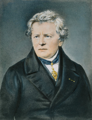
Georg Simon Ohm – German physicist and mathematician (1787–1854), known for Ohm's Law, relating voltage, current, and resistance.


What is Watt's Law and how is it used in electrical circuits?

Watt’s Law is a fundamental principle in electrical engineering that defines the relationship between power, voltage, and current in an electrical circuit. The formula is expressed as:

Power (Watts) = Voltage (Volts) × Current (Amperes)

In simpler terms, Watt’s Law states that the electrical power consumed by a device (measured in watts) is the product of the electrical potential difference (voltage) and the current flowing through the circuit. Accurate calculations using Watt’s Law often require a voltage-drop calculator to account for line losses in long-distance wiring. Comparing voltage drop and voltage sag conditions illustrates how slight changes in voltage can have a substantial impact on power output.


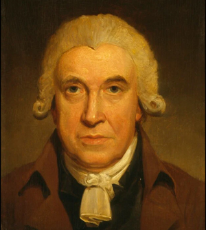
James Watt – Scottish inventor and mechanical engineer (1736–1819), whose improvements to the steam engine led to the naming of the watt (unit of power).


How is it used? Watt’s Law is widely used to determine the amount of power an electrical device or system consumes. This is especially important for designing electrical circuits, optimizing power distribution, and ensuring the efficiency of devices. Here are a few examples of how it’s applied:

  • Electrical Circuit Design: Engineers use it to calculate the power consumption of devices and ensure that circuits can handle the expected electrical load. This helps prevent overloads and ensures that the wiring is safe.

  • Power Output Calculations: Using this formula, you can calculate the power output of a generator, appliance, or device, enabling you to match the right components to your system's requirements.

  • Energy Efficiency: Understanding power consumption in appliances and devices helps consumers make informed choices, such as selecting energy-efficient options. Devices like wattmeters and watthour meters measure power and energy usage based directly on the principles of Watt’s Law. For a deeper look at how devices like ammeters help measure current, see how their readings plug directly into Watt’s Law calculations.


How is Watt's Law different from Ohm's Law?

Watt’s Law and Ohm’s Law are both fundamental principles in electrical engineering, but they deal with different aspects of electrical systems:

  • Watt’s Law defines the relationship between power, voltage, and current. It focuses on the amount of energy used by a device in a given circuit. The formula is:

           Power = Voltage × Current

  • Ohm’s Law defines the relationship between voltage, current, and resistance in a circuit. Ohm’s Law explains how the current is affected by the voltage and the resistance present in the circuit. The formula for Ohm’s Law is:

            Voltage = Current × Resistance


Key Differences:

  • Focus: It focuses on power, while Ohm’s Law focuses on the flow of electricity in a circuit, particularly how resistance affects current.

  • Watt’s Law is used to determine the amount of power a device is consuming. Ohm’s Law, on the other hand, is used to calculate current, voltage, or resistance in a circuit depending on the other known variables.

  • Applications: It is applied when designing systems that require power management, such as calculating the power output or efficiency of devices. Ohm’s Law is used more in analyzing how current behaves in a circuit when different resistive elements are present.

By combining both laws, electrical engineers can gain a comprehensive understanding of how electrical systems function, ensuring that devices operate efficiently and safely. When used with Ohm’s Law, Watt's Law enables engineers to analyze both energy consumption and electrical resistance.

One key area of application is in energy consumption. By understanding the voltage and current values for a specific device, engineers can monitor the amount of energy the device consumes. This is especially important for managing energy usage in homes, businesses, and power systems. By applying the formula, you can identify inefficient devices and make more informed decisions about energy efficiency.

In renewable energy systems, such as solar panels and wind turbines, this principle plays a critical role in optimizing energy output. Engineers use the formula to calculate how much electrical energy is being generated and distributed. This is crucial for ensuring that power systems operate efficiently and minimize excess energy loss.

Another practical application of this formula is in the automotive industry. It is used to design vehicle charging systems and battery technologies. For example, electric vehicle (EV) charging stations depend on understanding voltage, current, and power to ensure efficient charging times. Engineers use the equation to calculate the charging capacity required for EV batteries, helping to create optimal charging solutions.

In large facilities like data centers, this Watt’s Law formula is used to ensure power distribution is efficient. By applying the relationship between power, voltage, and current, engineers can effectively manage power systems, thereby reducing energy consumption and operational costs. Proper energy management in data centers is crucial, as high power usage can result in significant energy costs.

This power formula is indispensable for electrical engineers and technicians. The applications of Watt’s Law extend across various industries and are utilized in everything from designing power system wiring to developing renewable energy technologies. By combining Ohm’s Law and this principle, electrical engineers can optimize the performance of electrical components, ensuring energy efficiency and system reliability. Understanding the role of a resistor in a circuit can reveal how power is dissipated as heat, a key concept derived from Watt’s Law.

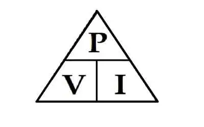
Finally, visual tools like the Watt's Law triangle are often used to simplify the application of this principle, helping both professionals and students understand how to apply the formula. As technology advances and energy demands grow, this formula remains a key element in electrical engineering, guiding the development of more efficient systems for the future.


Related Articles


View more

Nominal Voltage and AC and DC Standards

Nominal voltage is the standard voltage level assigned to electrical equipment or systems for identification. It helps ensure compatibility, performance, and safety across devices without indicating actual operating voltage, which may vary slightly.


What is Nominal Voltage?

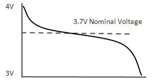
Nominal voltage refers to the labelled voltage value of an electrical system or device.

✅ Represents standard system voltage, not an  exact measurement

✅ Helps match equipment compatibility and safety standards

✅ Common in power distribution, residential, and industrial systems


Nominal voltage (NV) is a vital aspect of electrical systems, serving as a reference point for designing, manufacturing, and testing equipment. Additionally, it affects the performance, efficiency, and safety of electrical systems, with voltage regulation ensuring that voltage levels (V) remain within acceptable tolerances. Understanding the differences between nominal voltage, operating voltage (OV), and rated voltage (RV) is crucial for professionals and enthusiasts to ensure the effective operation and maintenance of electrical systems. To better understand how nominal voltage fits within broader system design, see our comprehensive overview on voltage.

It is vital to understand the definition and importance of nominal voltage in electrical systems. NV refers to the standard voltage value assigned to an electrical system, typically the voltage that electrical equipment is designed to operate under normal conditions. This value is crucial because it serves as a reference point for designing, manufacturing, and testing electrical equipment to ensure satisfactory performance. Maintaining voltage stability is essential—learn how voltage drop impacts performance and how to accurately calculate it.

Determining nominal voltage for electrical systems involves considering factors such as the type of equipment being used, the overall power requirements, and the voltage standards set by industry organizations. In some cases, the NV is set by the equipment manufacturer, while in others, it depends on the power grid's Voltage levels. Standard nominal voltages have been established to streamline equipment design and manufacturing processes. Use our voltage drop calculator to determine how wiring distance and load affect nominal voltage in real applications.

The terms NV, OV, and RV often appear in discussions about electrical systems. While they may seem interchangeable, each has a distinct meaning. As previously mentioned, nominal voltage is the standard voltage value designated for an electrical system. On the other hand, OV is the actual voltage at which equipment functions during operation. Similar to nominal voltage, RV refers to the maximum voltage at which equipment can operate continuously without sustaining damage. See how voltage regulators are used to maintain nominal levels and protect sensitive equipment.

Nominal voltage has a direct impact on the performance of electrical systems. Equipment designed for specific NVs operates safely within a particular voltage range. Operating outside this range can result in equipment damage, decreased efficiency, and even electrical fires. Therefore, it is essential to maintain the voltage levels as close as possible to the NV. Our guide to what is voltage explains the differences between nominal, operating, and actual voltage in power systems.

Electrical systems worldwide adhere to common national voltage (NV) standards for alternating (AC) and direct (DC) systems. For AC systems, NV  ranges include 110V, 220V, and 380V, while DC systems typically have NVs of 12V, 24V, or 48V. These standardized voltage levels enable the compatibility and interoperability of electrical equipment across various regions and industries. Learn how wattmeters and voltmeter tools help monitor nominal and real-time voltage values in field diagnostics.

Voltage regulation plays a critical role in controlling an electrical system's output voltage to ensure it remains within the acceptable voltage tolerance. Voltage regulation can be achieved through various means, including transformers, voltage regulators, and software algorithms in modern power systems. By maintaining NV, the electrical system The voltages more efficiently and safely, ensuring the longevity of the equipment.

The voltage tolerance is the range of voltage deviation from the nominal voltage value within which equipment can still operate effectively and safely. Different electrical systems have different voltage tolerances depending on the nature of the equipment and its intended use. For instance, a residential electrical system may have a voltage tolerance of +/- 5%, while an industrial system might tolerate a deviation of +/- 10%. Maintaining the acceptable V tolerance is crucial for the satisfactory operation of electrical equipment.


Nominal Voltage (NV) vs Operating Voltage (OV)

Nominal voltage and OV are two related yet distinct concepts in electrical engineering systems. Understanding the different essentials to ensure electrical systems' safe and efficient operation.

Nominal voltage refers to the standard or reference voltage level assigned to an electrical system, circuit, or device. It is the ideal voltage at which the equipment is designed to operate under normal conditions. NV is a baseline value that allows manufacturers, engineers, and technicians to design, test, and rate electrical equipment consistently.

Conversely, OV is the actual voltage level at which a particular electrical system, circuit, or device is functioning during real-time operation. Unlike nominal voltage, OV can fluctuate due to factors such as load changes, temperature variations, and power supply issues. Although electrical equipment is designed to operate optimally within a specified voltage range around the nominal voltage, slight variations in the operating V are often unavoidable.

In essence, NV serves as the benchmark or target voltage level, while OV reflects the real-world voltage conditions experienced by the electrical equipment. To ensure the efficient and safe operation of electrical systems, it is crucial to maintain the OV as close as possible to the NV. When the operating voltage falls within the acceptable voltage tolerance range, electrical equipment can function efficiently and safely without the risk of damage or performance degradation. Discover how alternating current systems rely on standardized nominal voltages like 120V or 240V for safe and consistent operation.


Nominal Voltage (NV) vs Rated Voltage (RV)

Nominal voltage and RV are related terms in electrical engineering but have distinct meanings and implications. Understanding the difference between the two is crucial for designing, operating, and maintaining electrical systems and devices properly. Differences between high voltage, medium voltage, and low voltage categories are based on standardized nominal values used in system classification.

It refers to the standard or reference voltage level assigned to an electrical system, circuit, or device. It is the ideal voltage at which the equipment is designed to operate under normal conditions. NV serves as a baseline value that enables manufacturers, engineers, and technicians to design, test, and rate electrical equipment consistently across various industries and applications.

On the other hand, RV is the maximum voltage at which an electrical device or component can operate continuously without incurring damage or experiencing a significant reduction in performance. RV is a critical parameter to ensure electrical equipment's safe and efficient functioning. Operating an electrical device within its RV range prevents excessive stress on the device, thereby reducing the risk of failure or shortened lifespan. Understanding the concept of electrical resistance is key to managing voltage drop and maintaining nominal voltage across circuits.

Nominal voltage is the target or reference Voltage level for the design and operation of electrical systems. In contrast, RV defines the maximum allowable Voltage for the continuous operation of electrical equipment. To ensure the efficient and safe performance of electrical systems, it is essential to maintain the operating voltage within the acceptable voltage tolerance range around the nominal voltage and not exceed the RV.  The relationship between power factor and nominal voltage affects system efficiency, especially in industrial electrical networks.


Related Articles


View more

Three Phase Electricity Explained

Three phase electricity delivers power using three alternating currents that are offset in phase. It provides consistent and efficient energy for industrial, commercial, and high-load applications, improving stability and reducing conductor size.


What is Three Phase Electricity?

Three phase electricity is a power system that uses three alternating currents, each offset by 120 degrees, to deliver constant power flow.

✅ Delivers more efficient and stable power than single-phase systems

✅ Ideal for large motors, commercial buildings, and industrial equipment

✅ Reduces conductor material and energy loss over long distances


Three phase voltage, frequency and number of wires

Three phase electricity is the dominant method of electrical power generation, transmission, and distribution across the industrialized world. Unlike single-phase systems, which rely on a single alternating current, three-phase systems use three separate currents, each 120 degrees out of phase with the others. This setup provides a consistent and balanced power flow, making it significantly more efficient for high-demand applications, such as motors, transformers, and large-scale infrastructure. Understanding the difference between alternating current and direct current is essential to grasp how three-phase systems deliver constant power using offset waveforms.


Understanding the Concept

At the heart of a three-phase system are three sinusoidal waveforms, evenly spaced to maintain a continuous flow of energy. When one phase reaches its peak, the others are in different parts of their cycle, ensuring that at any given moment, some power is being delivered. This creates what is known as constant power transfer, a major advantage over single-phase systems that experience power dips between cycles. Since three-phase systems rely heavily on accurate current flow measurement, it’s important to know what ammeters measure and how they help monitor system balance.

For industrial and commercial operations, this stability translates to increased energy efficiency, extended equipment lifespan, and reduced operating costs. Large electric motors, for example, run more smoothly on three-phase power, which avoids the surging and vibration commonly associated with single-phase inputs.


A Brief History

Three phase electricity wasn’t invented by a single person but emerged through the contributions of several pioneers in the late 19th century. Galileo Ferraris in Italy, Nikola Tesla in the United States, and Mikhail Dolivo-Dobrovolsky in Europe all played crucial roles in developing and refining the idea of three-phase alternating current. Tesla’s patents and Dolivo-Dobrovolsky’s practical systems laid the groundwork for what is now a global standard. Engineers use wattmeters to accurately measure real power in three-phase systems, while Watts Law helps calculate the relationships between voltage, current, and power.


Wye and Delta Configurations

Three-phase systems are typically wired in one of two configurations: the Wye (Y) or Delta (Δ) configuration. Each has specific advantages depending on the application:

  • In a Wye connection, each phase is tied to a central neutral point, allowing for multiple voltage levels within the same system. This is common in both commercial and residential applications, where both high and low voltages are required.

  • A Delta connection utilizes a closed loop with no neutral, a configuration commonly found in industrial setups. It delivers the same voltage between all phases and is ideal for running large motors without needing a neutral return path.

One of the most important relationships in these configurations is the √3 ratio between line voltage and phase voltage, a fundamental aspect that engineers use in calculating load, cable sizing, and protective device coordination.


Technical Benefits

Three-phase systems have built-in advantages that go beyond stability. Because the sum of the three phase currents is zero in a balanced load, a neutral wire is often unnecessary. This reduces the amount of conductor material needed, lowering costs and simplifying design. Additionally, three-phase motors naturally create a rotating magnetic field, eliminating the need for external circuitry to start or maintain rotation.

Another major benefit is that power output remains consistent. In single-phase systems, power drops to zero twice per cycle, but three-phase systems deliver non-pulsating power, which is especially important in sensitive or precision equipment. The function of a busbar is especially important in three-phase distribution panels, helping to manage multiple circuit connections efficiently.


Where and Why It’s Used

While most homes use single-phase electricity, three-phase is the standard in virtually all commercial and industrial environments. Factories, data centers, hospitals, and office buildings rely on it to power everything from HVAC systems and elevators to conveyor belts and industrial machines.

Three-phase is also common in electric vehicle (EV) charging stations and renewable energy systems, where efficient, high-capacity delivery is essential. If you're working with three-phase motors or transformers, knowing the role of a conductor and how electrical resistance affects current flow is fundamental to efficient design.

For sites that only have access to single-phase power, phase converters—whether rotary or digital—can simulate three-phase conditions, enabling them to operate three-phase equipment. This flexibility has made three-phase solutions accessible even in remote or rural areas. Three-phase systems often operate at medium voltage, especially in commercial settings, and their stability can reduce the risks of ground faults.


Voltage Levels and Color Codes

Depending on the region, the standard line and phase voltages vary. In North America, typical voltage values include 120/208 volts and 277/480 volts, whereas in Europe and much of Asia, 230/400 volts is more common. Wiring color codes also differ: red/yellow/blue in Europe, black/red/blue in North America, and other variations depending on the country's electrical code. These standards ensure safety, compatibility, and ease of troubleshooting.


The Global Standard for Power

Three-phase electricity is not just a technical solution; it is the foundation of modern electrical infrastructure. Its ability to deliver large amounts of power efficiently, safely, and reliably has made it the system of choice for more than a century. From powering the machines that build our world to the systems that keep us connected, three-phase electricity remains indispensable.


Related Articles


View more

3 PHASE ELECTRICITY

3 Phase Electricity supplies AC three-phase power via 120° phase-shifted sinusoidal waveforms, enabling balanced loads, higher power factor, efficient distribution, and smooth torque for industrial motors across commercial facilities and the electrical grid.


What Is 3 Phase Electricity?

An AC system with three sinusoidal phases delivering balanced, efficient power for distribution and industrial motors.

✅ Three 120° phase-shifted AC waveforms share balanced loads.

✅ Lower conductor size and losses than single-phase systems.

✅ Powers large motors with smoother torque and better efficiency.


3 phase electricity is referred to alternating current. It is best described as the timing of the electron movements. It is the most common delivery method worldwide because it is a cheaper and easier way to transmit power from one place to another. While this method of electrical transmission is popular in industrial, commercial and institutional power systems, most homes only use single-phase power. For a concise overview, see the three-phase electricity guide for context.


What does it mean?

If wires are in "phase", it means that timing of the electron movement, back and forth, is the same. The electrons are "in step" or "in time".

For newcomers, the basic electricity tutorial explains charge, current, and phase in simple terms.

To transmit and distribute alternating current, it is more efficient to use 3 circuits that are out of sequence. This idea was discovered by Nikola Tesla (1856 -1943). Much of its efficiency is because there is always voltage (electrons moving) in at least one wire.

You can review how alternating current behaves in circuits in the how electricity works resource to see why shifting phases improves continuity.

He found that it is an arrangement that fits in very nicely with generator design. The 120° phasing separation allows close to the optimum spacing and size of the copper conductors around the stator bore. The compatible generator is the cheapest form to make. Design notes for 3-phase power highlight how 120° spacing reduces copper and iron losses.

This type of power is designed especially for large electrical loads where the total electrical load is divided among the three separate phasing sequences. As a result, the wire and transformers will be less expensive than if these large loads were carried on a single system.

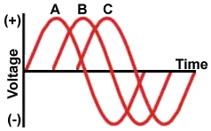
Generators usually have three separate windings, each producing its own separate single-phase voltage. Since these windings are staggered around the generator circumference, each of the voltages is "out of phase" with one another. That is, each of the three reaches the maximum and minimum points in the AC cycle at different times.

Definitions of "phase angle" and "phase sequence" are covered in the electricity terms glossary for reference.

Power is generated at electric utilities in this way. But, if this power is better than single phase, why not four, five or six phase? Theoretically, these would be even better, but equipment manufacturers would have to build motors to use it, and that just wouldn't be cost effective given the installed base of equipment that must continue to be powered. Utility practices for distribution are summarized in the electricity supply overview which also outlines standard voltage systems.

The word is often abbreviated using the Greek letter "phi" and is written as a zero with a slash mark through it.

The most important class of load is the electric motor. An induction motor has a simple design, inherently high starting torque, and high efficiency. Such motors are applied in industry for pumps, fans, blowers, compressors, conveyor drives, and many other kinds of motor-driven equipment. A motor will be more compact and less costly than a motor of the same voltage class and rating; and AC motors above 10 HP (7.5 kW) are uncommon. Three phase motors will also vibrate less and hence last longer than motor of the same power used under the same conditions.

Large air conditioning, etc. equipment use motors for reasons of efficiency, economy and longevity.

Resistance heating loads such as electric boilers or space heating may be connected to systems. Electric lighting may also be similarly connected. These types of loads do not require the revolving magnetic field characteristic of motors but take advantage of the higher voltage and power level usually associated with distribution. Fluorescent lighting systems also benefit from reduced flicker if adjacent fixtures are powered from different.

Large rectifier systems may have inputs; the resulting DC current is easier to filter (smooth) than the output of a rectifier. Such rectifiers may be used for battery charging, electrolysis processes such as aluminum production, or for operation of DC motors.

An interesting example of a load is the electric arc furnace used in steelmaking and in refining of ores.

In much of Europe stoves are designed to allow for a feed. Usually the individual heating units are connected between phase and neutral to allow for connection to a supply where this is all that is available.

For homeowners, the home electricity section explains single-phase panels, breakers, and typical loads.


Related Articles

View more

Power System Analysis Explained

Power System Analysis enables load flow studies, fault calculations, stability assessment, state estimation, and contingency analysis for grids, integrating SCADA data, protection coordination, and reliability planning to optimize transmission, distribution, and generation performance.


What Is Power System Analysis?

Power System Analysis models grid behavior to ensure stability, reliability, efficiency, and secure operation.

✅ Load flow, short-circuit, and transient stability studies

✅ State estimation, SCADA integration, and contingency analysis

✅ Protection coordination, reliability assessment, and optimization


Power system analysis (PSA) is an essential electrical system component. It helps to ensure that the electrical system operates efficiently, reliably, and safely. Power flow analysis, fault study, stability investigation, renewable energy integration, grid modernization, and optimization techniques are all essential concepts in PSA. As our society continues to rely heavily on electricity, PSA will remain a vital tool for ensuring the stability and reliability of the electrical system. For foundational context on how electricity underpins these studies, see this primer on what electricity is and how it behaves.

One of the critical concepts in PSA is power system modelling. Modelling is creating a mathematical model of the electrical system. This model includes all the system components, such as generators, transformers, transmission lines, and distribution networks. Modelling is essential as it provides a detailed understanding of the system's workings. Engineers commonly begin by drafting a single-line diagram to visualize component interconnections and power paths.

Another critical concept in PSA is power flow investigation, also known as load flow investigation. Power flow analysis calculates the electrical system's voltages, currents, and power flows under steady-state conditions. A power flow study helps determine whether the electrical system can deliver electricity to all the loads without overloading any system component. The results of the power flow investigation are used to plan the system's expansion and ensure that it operates efficiently and reliably. In practice, load-flow outputs are interpreted within the broader context of electric power systems to validate voltage profiles and thermal limits.

Fault study is another crucial component of PSA. A fault study is a process of analyzing the system's behaviour during a fault condition. This needs a short circuit analysis. A fault is abnormal when the system has a short or open circuit. A fault study helps to determine the fault's cause and develop strategies to prevent or mitigate the effects of faults in the future.

Stability investigation is also an important aspect of PSA. Stability investigation is the process of analyzing the system's behaviour under dynamic conditions. For example, the system is subject to dynamic disturbances, such as sudden load or generator output changes, which can cause instability. Stability investigation helps ensure the system can withstand these disturbances and operate reliably.

The transient investigation is another key concept in PSA. The transient study analyzes the electrical system's behaviour during transient conditions, such as switching operations or lightning strikes. A brief investigation helps ensure the system can withstand these transient conditions and operate reliably.

Renewable energy integration is an emerging concept in PSA. As more renewable energy sources, such as wind and solar power, are integrated into the energy system, PSA becomes increasingly essential to ensure the stability and reliability of the electrical system. Understanding how generation mixes are formed benefits from a primer on how electricity is generated across thermal, hydro, and renewable technologies.

Grid modernization is also a crucial aspect of PSA. As the system ages, it becomes increasingly important to modernize the grid to ensure that it can meet the demands of modern society. Therefore, PSA is used to develop strategies to modernize the grid and ensure it operates efficiently, reliably, and safely. Many modernization roadmaps align with the evolving architecture of the electricity grid as utilities adopt automation, advanced metering, and distributed resources.

Finally, protection coordination and optimization techniques are essential components of PSA. Protection coordination involves developing strategies to protect the electrical system from faults and other abnormal conditions. Optimization techniques involve developing strategies to optimize the system's operation and ensure it operates efficiently and reliably. Because reactive power and losses affect dispatch, monitoring and improving power factor can materially enhance system efficiency.


What is power system analysis, and why is it important?

PSA analyzes the electrical system to ensure it operates efficiently, reliably, and safely. Therefore, it is crucial to identify potential problems before they occur and develop strategies to prevent or mitigate the effects of these problems. In addition, PSA is important because it helps ensure that the electrical system can meet the demands of modern society, which relies heavily on electricity.


How is power flow analysis performed?

Power flow analysis, or load flow analysis, is performed using a mathematical model. The model includes all the power system components, such as generators, transformers, transmission lines, and distribution networks. A power flow study calculates the electrical system's voltages, currents, and power flows under steady-state conditions. The results of the power flow investigation are used to plan the electrical system's expansion and ensure that it operates efficiently and reliably. These studies also quantify reactive power behavior, making concepts like what power factor is directly applicable to planning and operations.


What is fault analysis, and how is it used?

Fault analysis is analyzing the system's behaviour during a fault condition. A fault is abnormal when the system has a short or open circuit. A fault study is used to determine the fault's cause and develop strategies to prevent or mitigate the effects of faults in the future. Fault analysis is crucial in ensuring the safety and reliability of the electrical system.


What are the different stability study techniques used?

Several stability investigation techniques are used in PSA to measure transient, small-signal, and voltage stability. Transient stability is used to analyze the behaviour of the distribution under dynamic conditions, such as sudden changes in load or generator output. Small-signal stability measurement analyzes the system's behaviour under small disturbances. Finally, voltage stability measurement is used to analyze the system's behaviour under steady-state conditions and determine the system's voltage limits.


How does renewable energy integration affect power system analysis?

Renewable energy integration is an emerging concept in PSA. As more renewable energy sources, such as wind and solar power, are integrated into the electrical system, PSA becomes increasingly essential to ensure the stability and reliability of the system. Renewable energy sources are intermittent, which can cause fluctuations in the system. PSA is used to develop strategies to integrate renewable energy sources into the system while ensuring its stability and reliability.


What are the challenges of grid modernization, and how does power system analysis help overcome them?

Grid modernization is a crucial aspect of PSA. As the system ages, it becomes increasingly important to modernize the grid to ensure that it can meet the demands of modern society. Grid modernization involves upgrading the system to incorporate new technologies, such as smart grid technologies and renewable energy sources. The challenges of grid modernization include the need for new infrastructure, the integration of new technologies, and new regulatory frameworks. PSA is used to develop strategies to overcome these challenges and to ensure that the electrical system operates efficiently, reliably, and safely.


How can optimization techniques improve system efficiency and reliability in power system analysis?

Optimization techniques can be used in PSA to improve system efficiency and reliability. These techniques involve developing strategies to optimize the system's operation and ensure it operates efficiently and reliably. For example, optimization techniques can determine the optimal generation and transmission of power, improve load forecasting, and develop strategies to reduce energy consumption. PSA is crucial in developing and implementing these optimization techniques, which help improve the electrical system's overall efficiency and reliability, leading to a more sustainable and cost-effective electrical power system.


Related Articles

View more

Sign Up for Electricity Forum’s Newsletter

Stay informed with our FREE Newsletter — get the latest news, breakthrough technologies, and expert insights, delivered straight to your inbox.

Electricity Today T&D Magazine Subscribe for FREE

Stay informed with the latest T&D policies and technologies.
  • Timely insights from industry experts
  • Practical solutions T&D engineers
  • Free access to every issue

Live Online & In-person Group Training

Advantages To Instructor-Led Training – Instructor-Led Course, Customized Training, Multiple Locations, Economical, CEU Credits, Course Discounts.

Request For Quotation

Whether you would prefer Live Online or In-Person instruction, our electrical training courses can be tailored to meet your company's specific requirements and delivered to your employees in one location or at various locations.