What is a Ground Fault? Hazard Explained

By R.W. Hurst, Editor


what is a ground fault

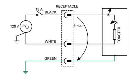
A ground fault occurs when electrical current unintentionally flows to the ground, often through a person or conductive surface. It poses serious shock and fire hazards and typically results from damaged wiring, insulation failure, or water intrusion in electrical systems.


What is a Ground Fault?

A ground fault is a potentially hazardous electrical event when an unintended electrical path forms between a live electrical conductor and a grounded surface.

✅ Occurs when electrical current flows to ground through an unintended path

✅ Commonly caused by damaged wires, insulation failure, or moisture

✅ Increases the risk of electrical shock and equipment failure

The flow of current through this unintended path, also known as earth leakage, can cause serious electrical shock hazards and damage to electrical systems. Let's examine the causes, dangers, and preventive measures associated with ground faults. Proper electrical grounding is essential to prevent ground faults, as it ensures that stray currents are safely diverted into the earth. 

There are common causes of ground faults. A ground fault occurs because of several factors, including damaged insulation, incorrect wiring, or moisture in the electrical system. Damaged insulation, for example, can expose the conductor of electricity, allowing it to come into contact with a grounded surface. Additionally, moisture can create a conductive path between live conductors and the earth, thereby increasing the risk. Moisture intrusion and damaged insulation can cause faults similar to arc faults, which are discussed further in our power quality troubleshooting resource.

One of the primary dangers associated with ground faults is the risk of electrical shock. When one occurs, it can create a path to the earth through a person, leading to serious injury or even death. Additionally, they can cause overheating, sparking, and fires in electrical systems, posing a significant risk to property and life.

Ground fault circuit interrupters (GFCIs) are essential devices designed to mitigate the risks associated with ground faults. GFCIs constantly monitor the flow of electrical current between the hot wire and the neutral wire. If an imbalance is detected, the GFCI quickly cuts power to the electrical circuit, preventing electrical shock and minimizing potential damage. GFCI outlets are commonly installed in areas where water is present, such as kitchens, bathrooms, and outdoor spaces, as these locations have a higher risk of ground faults. A grounding system should be regularly inspected to minimize the risk of fire and shock caused by unintentional current paths.


Preventing Ground Faults

Preventing and minimizing ground faults involves several steps. First, proper electrical grounding is critical in reducing the risk. A grounding wire connected to the electrical box creates a path for fault current to flow safely to the earth, reducing the likelihood of electrical shock. Regular inspection and maintenance of electrical systems can also help identify potential issues, such as damaged insulation or incorrect wiring, before they lead to ground faults. Additionally, using GFCI-protected outlets and circuit breakers in high-risk areas can help prevent ground faults and protect against shock hazards.

Understanding the differences between ground faults, short circuits, and arc faults is important, as they are all distinct electrical events with unique risks and causes. A short circuit occurs when a live conductor comes into contact with a neutral or grounded conductor, resulting in a sudden surge of current. This can lead to overheating, fires, or damage to electrical equipment. On the other hand, arc faults occur when an electrical arc forms between conductors, often due to damaged or frayed wiring. Arc faults can generate excessive heat and pose a fire risk.

Identifying one in an electrical system can be accomplished through visual inspection, testing, or the use of specialized equipment. For example, signs of a ground fault may include tripped GFCI outlets or circuit breakers, flickering lights, or a burning smell near electrical equipment. Additionally, testing outlets with a ground fault circuit interrupter tester or a multimeter can help determine if a ground fault is present.

Grounding is crucial in preventing ground faults and protecting against electrical shock. By providing a safe path for fault current to flow, earthing helps minimize the risk of injury and damage to electrical systems. Proper earthing involves connecting all electrical equipment, including outlets, switches, and metal boxes, to a grounding wire connected to the earth. This connection helps ensure that unintended electrical paths, such as those caused by ground faults, are safely grounded.


Understanding Ground Faults

Understanding what a ground fault is and how to prevent it is essential for ensuring electrical safety in residential and commercial settings. Proper earthing, regular inspection and maintenance of electrical systems, and the use of GFCI-protected outlets and circuit breakers are all crucial measures in reducing the risk of electrical hazards. By being aware of the dangers associated with ground faults and taking proactive steps to address them, we can help protect our homes, businesses, and loved ones from electrical hazards.

In addition to the precautions mentioned above, it's essential to exercise caution when using power tools and appliances. Many incidents occur when using power tools in damp environments. Always ensure that power tools are in good working condition, with no frayed cords or damaged insulation. Use GFCI-protected outlets or extension cords when operating them in potentially hazardous conditions.

Moreover, educating yourself and those around you about electrical safety is crucial. Understanding the risks associated with ground faults and knowing how to respond in an electrical emergency can save lives. Regularly reviewing safety procedures and ensuring that everyone in your home or workplace knows how to use GFCI outlets and reset buttons. Circuit breakers can significantly reduce the risk of injury or property damage.

Finally, don't hesitate to consult a licensed electrician if you suspect or encounter any electrical issues. Professional electricians have the knowledge and tools to diagnose and repair electrical problems safely and effectively. Attempting to resolve electrical issues without proper training can be dangerous and may lead to further complications.

By adopting a comprehensive approach to electrical safety, we can minimize risks and create a safer environment for ourselves and our communities. Awareness, preventive measures, and education are crucial in reducing the incidence of injuries and ensuring the well-being of everyone interacting with electrical systems.


Related Articles


Related News

What is a Voltmeter?

What is a voltmeter? A voltmeter is an electrical measuring instrument used to determine voltage across circuit points. Common in electronics, engineering, and power systems, it ensures accuracy, safety, and efficiency when monitoring current and diagnosing electrical performance.


What is a Voltmeter?

A Voltmeter provides a method to accurately measure voltage, which is the difference in electric potential between two points in a circuit, without changing the voltage in that circuit. It is an instrument used for measuring voltage drop.

✅ Ensures accurate voltage measurement for safety and performance

✅ Used in electrical engineering, electronics, and power systems

✅ Helps diagnose faults and maintain efficient operation

Electrical current consists of a flow of charge carriers. Voltage, also known as electromotive force (EMF) or potential difference, manifests as "electrical pressure" that enables current to flow. Given an electric circuit under test with a constant resistance, the current through the circuit varies directly in proportion to the voltage across the circuit. A voltmeter measures potential difference, which directly relates to Ohm’s Law, the fundamental equation connecting voltage, current, and resistance in circuits.

A voltmeter can take many forms, from the classic analog voltmeter with a moving needle to modern instruments like the digital voltmeter (DVM) or the versatile digital multimeter. These tools are essential for measuring electrical values in electronic devices, enabling technicians to measure voltage, current, and resistance with precision and accuracy. While analog units provide quick visual feedback, digital versions deliver more precise measurements across wider voltage ranges, making them indispensable for troubleshooting and maintaining today’s complex electrical systems.

A voltmeter can be tailored to have various full-scale ranges by switching different values of resistance in series with the microammeter, as shown in Fig. 3-6. A voltmeter exhibits high internal resistance because the resistors have large ohmic values. The greater the supply voltage, the larger the internal resistance of the voltmeter because the necessary series resistance increases as the voltage increases. To understand how a voltmeter works, it helps to first review basic electricity, as voltage, current, and resistance form the foundation of all electrical measurements.


Fig 3-6. A simple circuit using a microammeter (tA) to measure DC voltage.


A Voltmeter, whether digital or analog, should have high resistance, and the higher the better. You don't want the meter to draw a lot of current from the power source. (Ideally, it wouldn't draw any current at all.) The power-supply current should go, as much as possible, towards operating whatever circuit or system you want to use, not into getting a meter to tell you the voltage. A voltmeter is commonly used to measure voltage drop across conductors or devices, helping electricians ensure circuits operate efficiently and safely. For quick calculations, a voltage drop calculator provides accurate estimates of conductor losses based on length, size, and current. Understanding the voltage drop formula allows engineers and technicians to apply theoretical principles when designing or troubleshooting electrical systems.

Also, you might not want to keep the voltmeter constantly connected in parallel in the circuit. You may need the voltmeter for testing various circuits. You don't want the behavior of a circuit to be affected the moment you connect or disconnect the voltmeter. The less current a voltmeter draws, the less it affects the behavior of anything that operates from the power supply. Engineers often ask: What is a voltmeter?  They use a voltmeter in power system analysis, where accurate voltage readings are crucial for ensuring safety, reliability, and optimal performance.

Alternative types of voltmeters use electrostatic deflection, rather than electromagnetic deflection, to produce their readings. Remember that electric fields produce forces, just as magnetic fields do. Therefore, a pair of electrically charged plates attracts or repels each other. An electrostatic type utilizes the attractive force between two plates with opposite electric charges or a large potential difference. A voltmeter is used to measure the potential difference. Figure 3-7 portrays the functional mechanics of an electrostatic meter. It constitutes, in effect, a sensitive, calibrated electroscope. A voltmeter draws essentially no current from the power supply. Nothing but air exists between the plates, and air constitutes a nearly perfect electrical insulator. A properly designed electrostatic meter can measure both AC voltage and DC voltage. However, the meter construction tends to be fragile, and mechanical vibration can influence the reading.


Fig 3-7. Functional drawing of an electrostatic voltmeter movement.


It's always good when a voltmeter has a high internal resistance. The reason for this is that you don't want the voltmeter to draw a significant amount of current from the power source. This cur­rent should go, as much as possible, towards working whatever circuit is hooked up to the supply, and not just into getting a reading of the voltage. Additionally, you may not want or need to have the voltmeter constantly connected in the circuit; instead, you might need it for testing various circuits. You don't want the behavior of the circuit to be affected the instant you connect the voltmeter to the supply. The less current a voltmeter draws, the less it will affect the behavior of anything that is working from the power supply.

If you connect an ammeter directly across a source of voltage, a battery, the meter needle will deflect. In fact, a milliammeter needle will probably be "pinned" if you do this with it, and a microammeter might well be wrecked by the force of the needle striking the pin at the top of the scale. For this reason, you should never connect milli-ammeters or micro-ammeters directly across voltage sources. An ammeter, perhaps with a range of 0-10 A, may not deflect to full scale if it is placed across a battery; however, it's still a bad idea to do so, as it will rapidly drain the battery. Some batteries, such as automotive lead-acid cells, can explode under these conditions. This is because all ammeters have low internal resistance. They are designed that way deliberately. They are meant to be connected in series with other parts of a circuit, not right across the power supply. Because voltage is inseparable from current, learning what is current electricity provides deeper insight into why voltmeters are vital diagnostic tools.

But if you place a large resistor in series with an ammeter, and then connect the ammeter across a battery or other type of power supply, you no longer have a short cir­cuit. The ammeter will give an indication that is directly proportional to the voltage of the supply. The smaller the full-scale reading of the ammeter, the larger the resistance needed to get a meaningful indication on the meter. Using a microammeter and a very large resistor in series, it can be devised that draws only a small current from the source.

So, What is a Voltmeter? In summary, a voltmeter is a fundamental instrument for electrical work, allowing professionals and students to accurately measure voltage and understand circuit behaviour. Whether using an analog or digital design, voltmeters and multimeters provide precise insights that support safety, efficiency, and reliable performance in electrical systems.

Related Articles


View more

What is Electric Load

Electric load refers to the amount of electrical power consumed by devices in a system. It determines demand on the power supply and affects energy distribution, efficiency, and system design.


What is Electric Load?

✅ Measures the power consumed by electrical devices or systems

✅ Impacts system design, energy use, and load management

✅ Varies by time, usage patterns, and connected equipment

What is electric load? It refers to the total power demand placed on a circuit by connected devices. Electric load, such as lighting, motors, and appliances, impacts energy use, system sizing, and overall efficiency across residential, commercial, and industrial settings.

An electric load refers to any device or system that consumes electric power to perform work, such as an electric motor, lighting fixture, or household electrical appliances. These loads draw electrical energy from the power source, impacting both system efficiency and capacity planning. Accurate electrical load calculation is crucial for designing circuits, selecting the correct breakers, and ensuring safe operation in homes, businesses, and industrial facilities. Using real-time monitoring tools, engineers can assess load patterns, identify peak demand, and implement energy-saving strategies through smart load management systems.

An electric load can be anything that consumes power, such as lights, appliances, heating systems, motors, and computers. In electrical engineering, a load represents the demand that a device or installation places on the power source.

Electric load is closely influenced by regional consumption patterns, which can be explored in more detail in Electricity Demand in Canada, highlighting how climate and industry shape national power usage.

Different types of types exist, and they are classified based on their characteristics. Resistive loads include, for example, converting energy directly into heat, such as heaters or incandescent light bulbs. Inductive loads, however, require energy to create a magnetic field, such as motors or transformers. Capacitive loads, meanwhile, store and release energy, such as capacitors used in a powered circuit.


An electric load refers to any device or circuit that consumes energy in a system. A common example is a load that consists of appliances such as heaters or ovens, where the primary component is a heating element. This heating element converts energy into heat, providing warmth or cooking power. It consists of a heating mechanism that demands specific amounts of powered energy depending on the device’s power requirements, which is crucial for maintaining an efficient and balanced system. For readers new to electrical concepts, the Basic Electricity Handbook provides foundational knowledge that helps contextualize the meaning of electricity in power systems.


Types of Electrical Loads

Electric loads fall into three primary categories:

  • Resistive: Devices like incandescent light bulbs, heaters, and toasters. These convert energy directly into heat.

  • Inductive: Motors, transformers, and fans. Inductive loads create magnetic fields to operate, often resulting in a lagging power factor.

  • Capacitive: Capacitors are used in power factor correction equipment or some specialized electronic devices. They store energy temporarily.

Each load type interacts differently with the system, impacting both efficiency and stability.

Related: Understand how resistive loads behave in a circuit.


How to Calculate Electric Load

Accurately calculating electric load is important for selecting the correct wire size, circuit breakers, and transformer ratings.


For example:

  • If a device operates at 120 volts and draws 5 amps:

    • Load = 120 × 5 = 600 watts


Step-by-Step Example for a Household Circuit:

  1. Add up the wattage of all devices on the circuit.

  2. Divide the total wattage by the system voltage to find the total current load.

  3. Compare the load to the circuit breaker rating to ensure it is not overloaded.

Tip: Always design for 80% of breaker capacity for safety.


Why Understanding Electric Load Matters

Understanding electric load has real-world implications:

  • Energy Bills: Higher demand results in higher costs, particularly for businesses subject to demand charges.

  • System Design: Correct assessment ensures that wiring, transformers, and protection devices are appropriately sized.

  • Power Quality: Poor management can lead to low power factor, voltage drops, and even system instability.

  • Maintenance Planning: Predictable loads extend the life of equipment and reduce costly downtime.


Management Strategies

Smart load management can improve system efficiency and reduce costs:

  • Peak Shaving: Reducing consumption during periods of high demand.

  • Shifting: Moving heavy loads to off-peak hours.

  • Power Factor Correction: Installing capacitors to improve system efficiency and lower bills.


Electric load is a critical concept in both residential and industrial settings. By understanding the types of calculations used to determine total demand and the practical impacts on energy costs and system design, you can build safer, more efficient systems.

One critical aspect is the power factor. Power factor is the ratio of active power (measured in watts) to apparent power (measured in volt-amperes). In simpler terms, it is the efficiency of energy usage. A low power factor indicates that a device or system consumes energy more than necessary to perform a given task, leading to higher energy costs and increased strain on the power grid. The relationship between load, bill, and motor is especially evident in provincial models, such as Ontario’s Electricity Cost Allocation, which explains how peak demand affects consumer rates.

An electric load is a critical concept in the design and operation of the power grid. Understanding how it is measured, the different types, power factor, management strategies, peak, shedding, and demand response programs are essential for optimizing the use of the grid and ensuring its reliability. By balancing the demand for power with the grid's capacity, we can reduce energy costs, prevent blackouts, and create a more sustainable energy system. Management is a critical component of infrastructure planning, as discussed in the Transmission & Distribution Channel, which examines how levels affect grid design and performance.

In industrial environments, managing efficiently can lead to significant cost savings and operational stability. Explore these strategies in the Industrial Electric Power Channel.


View more

What is a Potentiometer?

A potentiometer is a variable resistor that adjusts voltage in a circuit. It’s used for controlling electrical devices like volume knobs, sensors, and dimmers. Potentiometers regulate current flow by varying resistance, making them essential in analog electronic applications.


What is a Potentiometer?

A potentiometer is a type of adjustable resistor used to control voltage or current in an electrical circuit.

✅ Adjusts resistance to control voltage in circuits

✅ Commonly used in audio controls and sensors

✅ Essential for analog signal tuning and regulation

At its core, a potentiometer functions as a variable resistor. By moving the wiper (a movable terminal) across a resistive element, the device varies the output voltage. Depending on the position of the wiper, varying amounts of resistance are introduced into the circuit, thereby adjusting the current flow.

When the wiper moves along the resistive track, it adjusts the total resistance in the circuit, which controls the flow of current. To learn more, see our guide on Electrical Resistance.

A potentiometer acts as an adjustable Voltage divider, splitting the input voltage proportionally between two output terminals based on the wiper’s position.

This relationship is governed by Ohm’s Law Formula, which states that voltage equals current multiplied by resistance (V = IR).

As shown in Figure 6-8, the basic construction of a potentiometer includes:

  • A resistive track (usually carbon, cermet, or wire wound)

  • A movable wiper

  • Three terminals (two fixed, one connected to the wiper)

This setup enables the potentiometer to function as both a voltage divider and a simple variable resistor.


Fig. 6-8 Construction geometry of a potentiometer


Types of Potentiometers

Potentiometers come in several forms, each designed for specific applications:

A potentiometer is considered a variable resistor, one of several important types covered in our guide to Types of Resistors.


Rotary Potentiometer

The most common type, rotary potentiometers, adjust resistance through the rotation of a knob. These are frequently found in volume controls, light dimmers, and measuring instruments. The resistive track inside a potentiometer is made from materials that partially conduct electricity, such as carbon or cermet. For more on conductive materials, see Conductor of Electricity.


Figure 6-9 illustrates the typical circuit symbol for a rotary potentiometer.


Linear Potentiometer (Slide Potentiometer)

Instead of rotating, a linear potentiometer, often referred to as a slide potentiometer, adjusts by sliding a control lever. These are widely used in audio mixers and precision instruments where fine, linear adjustments are needed.


Audio Taper Potentiometer

In audio equipment, human hearing sensitivity is non-linear. Audio taper potentiometers adjust resistance logarithmically to provide a natural, smooth volume change that matches human perception.

Note: If you use a linear-taper potentiometer for audio volume control, the sound may seem to jump suddenly instead of increasing smoothly.


Digital Potentiometer

Digital potentiometers, also known as "digipots," are electronically controlled rather than manually adjusted. They find use in automatic tuning circuits, programmable amplifiers, and microcontroller applications.


Rheostat (Variable Resistor)

Although technically a type of potentiometer, a rheostat uses only two terminals: one fixed terminal and the wiper. It is optimized to control current rather than voltage. Rheostats are commonly used in applications like motor speed control and light dimming.


Practical Applications of Potentiometers

Potentiometers are found in a wide range of everyday and industrial applications:

  • Audio Equipment: Volume and tone controls on stereos and guitars

  • Automobiles: Throttle position sensors, dashboard dimmers

  • Industrial Controls: Machinery speed adjustments

  • Consumer Electronics: Game controller joysticks

  • Laboratory Equipment: Calibration and fine adjustments

Potentiometers are versatile components used in both AC and DC electrical systems, from audio controls to automotive sensors.

Their ability to fine-tune voltage and resistance makes them essential in both analog and digital systems.


How to Test a Potentiometer

Testing a potentiometer is straightforward:

  1. Disconnect power to the circuit.

  2. Use a multimeter set to measure resistance (ohms).

  3. Connect the multimeter probes to the outer two terminals to measure total resistance.

  4. Measure between the wiper and one outer terminal; adjust the control and observe the changing resistance.

Consistent, smooth changes confirm proper operation. Jumps or dead spots may indicate a worn or faulty potentiometer.

A potentiometer is a simple but versatile component that provides adjustable control over voltage or resistance in a circuit. Whether used in audio systems, automotive sensors, or industrial machinery, its importance in electronic design and control systems is undeniable.

Understanding the various types and practical applications of potentiometers can help in selecting the appropriate device for a specific task.

For readers seeking a broader understanding of basic electrical principles, visit our overview of Electricity Fundamentals.


Frequently Asked Questions


What is the difference between a potentiometer and a rheostat?

A potentiometer typically acts as a voltage divider with three terminals, while a rheostat uses only two terminals to control current.


Where are potentiometers commonly used?

Potentiometers are used in volume controls, sensors, gaming controllers, industrial equipment, and calibration tools.


How does a potentiometer adjust voltage?

By moving the wiper across the resistive track, a potentiometer divides the input voltage proportionally between the two output terminals, adjusting the output voltage.


Related Articles


View more

What is a Busbar?

A busbar is a metallic strip or bar used in electrical systems to conduct electricity within switchgear, distribution panels, and substations. It distributes power efficiently and reduces resistance, enhancing safety and electrical performance.


What is a Busbar?

A busbar is a crucial electrical component used to conduct, distribute, and manage power in electrical systems. Found in commercial, industrial, and utility applications, it helps centralize connections and minimize wiring complexity.

✅ Provides efficient power distribution in electrical panels and substations

✅ Reduces resistance and improves system reliability

✅ Supports compact, organized electrical design for switchgear and distribution boards

A Busbar is an important component of electrical distribution systems, providing a central location for power to be distributed to multiple devices. It is an electrical conductor responsible for collecting electrical power from incoming feeders and distributing it to outgoing feeders. They are made of metal bars or metallic strips and have a large surface area to handle high currents.

How Does it Work?

It is a strip or bar made of copper, aluminum, or another conductive metal used to distribute electrical power in electrical systems. They have a large surface area to handle high currents, which reduces the current density and minimizes losses. They can be insulated or non-insulated, and they can be supported on insulators or wrapped in insulation. They are protected from accidental contact by either a metal earthed enclosure or elevation out of normal reach.

They collect electrical power from incoming feeders and distribute it to outgoing feeders. The bus bar system provides a common electrical junction for various types of electrical equipment, designed to handle high currents with minimal losses. They are often used in industrial applications, where they are installed in electrical panels or switchgear panels.


Different Types of Busbars

Different types of busbars are available on the market, including those made of copper or aluminum, as well as insulated or non-insulated, and segmented or solid busbars. Copper or brass busbars are used in low-voltage applications, while aluminum busbars are used in high-voltage applications. Insulated busbars are used in situations where accidental contact can occur, and segmented busbars are used to connect different types of equipment.

Busbars can also be classified based on their cross-section. A rectangular is the most common type and is often used in low-voltage applications. On the other hand, a tubular busbar is a hollow cylinder used in high-voltage applications. Finally, a circular one has a circular cross-section and is used in high-current applications.


Busbar Types and Characteristics

Attribute Copper Busbar Aluminum Busbar Laminated Busbar
Conductivity Excellent (≈100% IACS) Good (≈61% IACS) Varies (depends on internal conductor materials)
Weight Heavy Lightweight Moderate
Cost Higher Lower Higher (due to fabrication complexity)
Heat Dissipation Excellent Good Excellent (designed to reduce hot spots)
Applications Switchgear, substations, panels Bus ducts, high-rise buildings Compact power modules, UPS, power electronics
Mechanical Strength High Moderate Moderate to High
Corrosion Resistance High (especially tinned copper) Requires anodizing/coating Depends on encapsulation
Ease of Fabrication Good Excellent Complex


The Purpose of a Busbar in an Electrical System

The primary purpose of an electrical system is to distribute electrical power to different parts of the system. The busbar system collects electrical power from incoming feeders and distributes it to outgoing feeders. Busbars also provide a common electrical junction for different types of electrical equipment.


Busbar and Circuit Breakers

They are often used in conjunction with circuit breakers. Circuit breakers protect electrical circuits from damage caused by overload or short circuits. Additionally, they can be used to isolate the electrical supply in the event of a fault or overload. Circuit breakers are often installed in electrical or switchgear panels, which can be easily accessed and maintained.


Busbars and Electrical Distribution Equipment

They are an essential component of electrical distribution equipment, including electrical panels, switchgear panels, and distribution boards. Electrical panels distribute power to various parts of a building, while switchgear panels control the flow of electrical power in industrial applications. Distribution boards divide the electrical supply into separate circuits at a single location.


Busbar Installation

Installing a busbar involves several basic steps. First, the busbar system's design must be created, considering both the electrical load and the required current-carrying capacity. Then, it is installed in the electrical panel or switchgear panel. Finally, it is connected to the electrical equipment using either bolts, clamps, or welding.


Maintenance

Maintaining a busbar system involves regular inspections and cleaning. The system should be inspected for any damage or corrosion, and the connections should be tightened if they become loose. Regular cleaning of the system is also essential to prevent the buildup of dust or dirt, which can lead to a short circuit.


Safety Precautions

Working with busbars involves high voltage and current, so taking proper safety precautions is essential. The system must be isolated from the electrical system before any maintenance is performed. Personal protective equipment, such as gloves and safety glasses, should be worn while working with busbars. Working on a live system should only be done by trained personnel after ensuring that all necessary safety precautions are in place.


Accidents involving Busbars

Accidents can occur when working with busbars, and they can be dangerous if proper safety precautions are not taken. One common accident that can occur involves accidental contact with a live one. This can cause electrical shock, burns, and even death. Another accident involves short circuits, which can lead to equipment damage, fire, or explosions. These accidents can be prevented by following proper safety procedures and wearing personal protective equipment.

Arc flash accidents, including busbars, are a potential hazard when working with electrical equipment. An arc flash is an electrical explosion that can occur when a fault occurs in an electrical circuit, resulting in a short circuit or electrical discharge. Arc flash accidents can cause severe burns, hearing loss, and even death.

They can be a source of arc flash accidents if proper safety precautions are not taken. For example, if a live busbar comes into contact with an object, it can cause an arc flash. Proper insulation and guarding are necessary to prevent arc flash accidents involving busbars. They should also be installed in a way that minimizes the possibility of accidental contact.

Additionally, they should be designed to handle the expected current load, as overloading can lead to a fault and an arc flash. It is also essential to follow proper maintenance procedures, including regular system inspections and cleaning, to prevent damage or corrosion that can cause faults and arc flashes.

Overall, busbars are related to arc flash accidents as they can be a source of electrical faults that can lead to an arc flash. Therefore, following proper safety procedures, including proper insulation, guarding, and system maintenance, is crucial to prevent arc flash accidents.


Related Articles


View more

What is a Watt? Electricity Explained

A watt is the standard unit of power in the International System of Units (SI). It measures the rate of energy transfer, equal to one joule per second. Watts are commonly used to quantify electrical power in devices, circuits, and appliances.


What is a Watt?

A watt is a unit that measures how much power is used or produced in a system. It is central to understanding electricity and energy consumption.

✅ Measures the rate of energy transfer (1 joule per second)

✅ Commonly used in electrical systems and appliances

✅ Helps calculate power usage, efficiency, and energy costs

A watt is a unit of power, named after engineer James Watt, which measures the rate of energy transfer. A watt is a unit of power that measures the rate at which energy flows or is consumed. One watt is equivalent to one joule per second. In terms of electrical usage, 1,000 watt hours represent the amount of energy consumed by a device using 1,000 watts over one hour. This concept is important for understanding power consumption across devices on the electric grid. The watt symbol (W) is commonly used in electricity to quantify power, and watts measure power in various contexts, helping to track energy flow efficiently.


Frequently Asked Questions

How does a watt relate to energy?

A watt is a unit of power that measures the rate at which energy is consumed or produced. Specifically, one watt equals one joule per second, making it a crucial unit in understanding how energy flows.


How is a watt different from a watt-hour?

A watt measures power, while a watt-hour measures energy used over time. For instance, if you use a 100-watt bulb for 10 hours, you've consumed 1,000 watt-hours of energy.


How many watts does a typical household appliance use?

Wattage varies between appliances. For example, a microwave uses 800 to 1,500 watts, while a laptop typically uses between 50 to 100 watts. Understanding the wattage helps estimate overall power consumption.


What does it mean when a device is rated in watts?

A device’s watt rating indicates its power consumption when in use. A higher wattage means the device draws more power, leading to higher energy costs if used frequently.


How can I calculate power consumption in watts?

To calculate power in watts, multiply the voltage (volts) by the current (amperes). For example, a device using 120 volts and 10 amps will consume 1,200 watts. A watt, in electrical terms, is the rate at which electrical work is done when one ampere (A) of current flows through one volt (V). Formula:

W= A* V

Whenever current flows through a resistance, heat results. This is inevitable. The heat can be measured in watts, abbreviated W, and represents electrical power. Power can be manifested in many other ways, such as in the form of mechanical motion, or radio waves, or visible light, or noise. In fact, there are dozens of different ways that power can be dissipated. But heat is always present, in addition to any other form of power in an electrical or electronic device. This is because no equipment is 100-percent efficient. Some power always goes to waste, and this waste is almost all in the form of heat.

There is a certain voltage across the resistor, not specifically given in the diagram. There's also electricity flowing through the resis­tance, not quantified in the diagram, either. Suppose we call the voltage E and the cur­rent I, in volts and amperes, respectively. Then the power in watts dissipated by the resistance, call it P, is the product E X I. That is:

P (watts) = El

This power might all be heat. Or it might exist in several forms, such as heat, light and infrared. This would be the state of affairs if the resistor were an incandescent light bulb, for example. If it were a motor, some of the power would exist in the form of me­chanical work.

If the voltage across the resistance is caused by two flashlight cells in series, giving 3 V, and if the current through the resistance (a light bulb, perhaps) is 0.1 A, then E = 3 and I = 0.1, and we can calculate the power P, in watts, as:

P (watts) = El = 3 X 0.1 = 0.3 W

Suppose the voltage is 117 V, and the current is 855 mA. To calculate the power, we must convert the current into amperes; 855 mA = 855/1000 = 0.855 A. Then we have: 

P (watts) = 117 X 0.855 = 100 W

You will often hear about milliwatts (mW), microwatts (uW), kilowatts (kW) and megawatts (MW). You should, by now, be able to tell from the prefixes what these units represent. But in case you haven't gotten the idea yet, you can refer to Table 2- 2. This table gives the most commonly used prefix multipliers in electricity and electron­ics, and the fractions that; they represent. Thus, 1 mW = 0.001 W; 1 uW = 0.001 mW = 0.000001 W; 1 kW = 1-flOO W; and 1 MW = 1,000 kW = 1,000, 000 W.

Sometimes you need to use the power equation to find currents or voltages. Then you should use I = P/E to find current, or E = P/I to find power. It's easiest to remem­ber that P = El (watts equal volt-amperes), and derive the other equations from this by dividing through either by E (to get I) or by I (to get E).

A utility bill is measured in kilowatt hours, usually in 1,000 watt increments. A watt is a unit of electrical energy in which the units of measurement (watts and watt hours) are agreed to by an international system of units si called watts. The amout of energy is measured this way.


Related Articles


View more

What is Low Voltage?

Low voltage refers to electrical systems operating at 50 to 1000 volts AC or 120 to 1500 volts DC. Common in residential, commercial, and control circuits, it reduces shock risks while powering lighting, HVAC, security systems, and automation equipment safely.


What is Low Voltage?

Low voltage is a range of electrical power levels below high-voltage thresholds.

✅ Reduces risk of electrical shock in residential and commercial settings

✅ Powers lighting, security, HVAC, and control systems

✅ Common in telecommunications and automation applications


In today's technologically driven world, understanding the concept of low voltage (LV) is essential. Low voltage systems are widely used across industries, homes, and offices, making them an integral part of our daily lives. This article provides an overview of LV, its applications, safety measures, and regulations, incorporating the keywords provided. Low voltage systems are designed to operate below 600 volts, unlike high voltage systems that present increased shock hazards.

The low voltage definition is relatively simple: Any electrical system or equipment operating at a voltage level less than or equal to 600 volts. LV systems in the United States are generally categorized as those working between 50 and 600 volts. These systems are utilized in various applications due to their low power consumption and reduced risk of electric shock. Understanding the concept of voltage is essential when working with residential or industrial low voltage wiring.


Applications

Low voltage applications are diverse and include control rooms, distribution systems, lighting, communication systems, and security systems. LV wiring is often used in these applications, as it is designed for smaller currents and offers increased safety compared to regular wiring. This wiring type is also more cost-effective and easier to install. Voltage drop can significantly impact the performance of low voltage circuits, especially over long wiring runs.

Regarding LV safety, it is crucial to take necessary precautions as even LV electrical equipment can pose risks. For example, to minimize the chance of electric shock, one should always turn off the power supply before working on any electrical equipment and use insulated tools. Additionally, it is essential to adhere to local LV regulations and standards to ensure a safe working environment.


Devices

Low voltage devices are found in various settings, from residential to commercial and industrial. Some examples of low voltage devices include thermostats, doorbells, intercom systems, and landscape lighting. These devices usually require transformers to convert the higher voltage from the main power supply to a lower voltage suitable for operation.

Regulations and standards for LV installations vary by country and region. However, the National Electrical Code (NEC) provides guidelines and requirements for LV installations to ensure safety and reliability in the United States. Professionals working with low voltage systems must adhere to these guidelines and any additional local regulations.

Low voltage transformers and power supplies are critical in distributing low voltage electricity. Transformers are used to step down higher voltages from the main power supply to the required LV level. In contrast, power supplies regulate and distribute electrical energy to various devices. Low voltage distribution systems are designed to efficiently deliver electricity to low voltage equipment while maintaining safety and reliability.


Systems

While low voltage systems are generally safer than high voltage electrical systems, they still require proper handling and adherence to safety measures. High-voltage transmission systems are used to transport electricity over long distances from power plants to substations. High voltages range from 100 kV to 765 kV, while ultra-high voltages can reach above 800 kV. Large industrial facilities, such as factories that use medium-voltage systems, typically operate between 1 kV and 35 kV.

Understanding LV is crucial today, as these systems are widely used in various applications. With proper installation, adherence to regulations, and safety precautions, LV systems can provide numerous devices with an efficient and reliable power supply. As a result, low voltage systems play an essential role in our daily lives, whether for lighting, communication, or security. Key electrical components such as resistors and capacitors are frequently used in low voltage control systems.


Frequently Asked Questions


Is "low voltage" defined differently in 110V systems and 220V systems?

While the term "low voltage" describes electrical systems operating at a voltage level lower than a certain threshold, the specific voltage ranges considered low voltage can vary slightly between countries and regions due to differences in their electrical distribution systems. However, the general concept remains the same across 110V systems in North America and 220V systems in the EU. For efficient power distribution, low voltage systems rely on solid grounding practices, making ground faults and electrical faults important safety considerations.

In North America, low voltage typically refers to electrical systems operating between 50 and 600 volts. In contrast, in the EU, the term "LV" is defined by the Low Voltage Directive (LVD), which covers electrical equipment designed for use with a voltage rating of 50 to 1000 volts for alternating current (AC) and 75 to 1500 volts for direct current (DC).

Despite these minor differences in the defined voltage ranges, the reasons behind the classification of LV systems remain consistent. LV systems are generally considered safer than their high voltage counterparts, as the risk of electric shock is lower. Additionally, they consume less power, making them more energy-efficient and cost-effective for certain applications.

The main factor causing the difference in voltage levels between regions is the choice of electrical distribution systems. For example, 110-120V systems are more common in North America, while in Europe and many other parts of the world, 220-240V systems are standard. This difference is primarily due to historical reasons and the evolution of each region's electrical infrastructure over time.

Regardless of these regional differences in voltage levels, the fundamental principles and safety considerations for LV systems remain largely the same. Both 110V and 220V systems use LV electrical equipment and wiring to provide power for various applications while adhering to regional safety standards and regulations to ensure these systems' safe and efficient operation. The behavior of current in low voltage applications is best understood by applying Ohm’s Law, which explains the relationship between voltage, current, and resistance.


What are examples of low voltage systems?

Low voltage systems are widely used in various residential, commercial, and industrial applications due to their increased safety and energy efficiency. Here are some examples of LV systems:

Lighting systems: Low voltage lighting, such as LED lights and halogen lamps, is commonly used for residential and commercial purposes, including landscape lighting, recessed lighting, and track lighting. These systems often use transformers to step down the voltage from the main power supply to a suitable level for the lights.

Security systems: LV is used in security systems, including alarm systems, access control systems, and surveillance cameras. These systems require a stable and reliable power source with minimal risk of electrical hazards.

Communication systems: LV wiring is utilized in various communication systems, including intercoms, telephone lines, and data networks. It enables the reliable transmission of data and voice signals while minimizing energy consumption and interference.

Audio and video systems: LV components are used in home theatre systems, speakers, and AV equipment. The low voltage wiring ensures minimal signal loss and interference for better audio and video quality.

HVAC controls: Thermostats, sensors, and control panels for heating, ventilation, and air conditioning systems often use low voltage wiring and components to maintain efficient energy use and reliable control of the HVAC system.

Doorbells and chimes: LV systems are commonly used in doorbells and chime systems to ensure safe and reliable operation.

Fire alarm systems utilize LV wiring and components to provide a reliable means of detecting and responding to potential fire hazards while minimizing the risk of electrical hazards.

Home automation systems often utilize LV for controlling and automating various devices, including lighting, appliances, and security systems. This allows for the energy-efficient and safe operation of connected devices.

Solar power systems: In small-scale solar power installations, LV DC systems are used to store and distribute the electricity generated by solar panels. These systems typically include charge controllers, batteries, and inverters to efficiently manage the power supply.

Industrial control systems: LV is used in various industrial applications to control and monitor machinery and equipment. This includes programmable logic controllers (PLCs), motor controls, and sensor networks, which require stable and reliable power sources with minimal risk of electrical hazards. Devices like multimeters and voltmeters are essential tools for testing and maintaining low voltage installations.


Related Articles


View more

Sign Up for Electricity Forum’s Newsletter

Stay informed with our FREE Newsletter — get the latest news, breakthrough technologies, and expert insights, delivered straight to your inbox.

Electricity Today T&D Magazine Subscribe for FREE

Stay informed with the latest T&D policies and technologies.
  • Timely insights from industry experts
  • Practical solutions T&D engineers
  • Free access to every issue

Live Online & In-person Group Training

Advantages To Instructor-Led Training – Instructor-Led Course, Customized Training, Multiple Locations, Economical, CEU Credits, Course Discounts.

Request For Quotation

Whether you would prefer Live Online or In-Person instruction, our electrical training courses can be tailored to meet your company's specific requirements and delivered to your employees in one location or at various locations.