Voltage Drop Formula
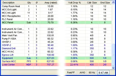

Voltage Drop Formula

The voltage drop formula is V = I × R, where V represents the voltage drop, I represents the current in amperes, and R represents the resistance in ohms. It calculates the amount of voltage lost through a conductor and is essential for designing safe and efficient electrical systems.


What is Voltage Drop Formula?

A voltage drop formula can help you manually calculate the voltage drop in cables under full load in branch circuits. It does not matter if you are working with copper or aluminum conductors. To accurately calculate the voltage drop for a given cable size, length, and current, you need to know the resistance of the type of cable you’re using. 

✅ V = I × R for DC circuits

✅ Accounts for impedance in AC circuits

✅ Helps ensure safe, efficient electrical design

Use our voltage drop calculator to quickly determine wire size, conductor efficiency, and line loss for safer, more reliable electrical installations.


Power Quality Analysis Training

Power Factor Training

Request a Free Power Quality Training Quotation

To determine voltage drop in an electrical system, engineers and electricians use a standard formula that accounts for conductor resistance, current, and circuit length. The National Electrical Code (NEC) provides guidelines for the maximum voltage drop allowed in various installations to ensure efficiency and safety. For both single-phase and three-phase circuits, excessive voltage drop can lead to poor equipment performance and energy loss. To simplify calculations, a voltage drop calculator can quickly assess whether a circuit meets NEC recommendations and optimize conductor sizing accordingly. You can learn more about how electrical resistance affects circuits in our detailed voltage drop guide, which explains causes, calculations, and solutions for safe, efficient power distribution.


DC / single phase calculation

The voltage drop V in volts (V) is equal to the wire current I in amps (A) times 2 times one way wire size length L in feet (ft) times the wire resistance per 1000 feet R in ohms (Ω/kft) divided by 1000:


Vdrop (V) = Iwire (A) × Rwire(Ω)

Iwire (A) × (2 × L(ft) × Rwire(Ω/kft) / 1000(ft/kft))


The voltage drop V in volts (V) is equal to the wire current I in amps (A) times 2 times one way wire length L in meters (m) times the wire resistance per 1000 meters R in ohms (Ω/km) divided by 1000:


Vdrop (V) = Iwire (A) × Rwire(Ω)

Iwire (A) × (2 × L(m) × Rwire (Ω/km) / 1000(m/km))


3 phase calculation

The line-to-line voltage drop V in volts (V) is equal to the square root of 3 times the wire current I in amps (A) times one-way wire length L in feet (ft) times the wire resistance per 1000 feet R in ohms (Ω/kft) divided by 1000:


Vdrop (V) = √3 × Iwire (A) × Rwire (Ω)

= 1.732 × Iwire (A) × (L(ft) × Rwire (Ω/kft) / 1000(ft/kft))


The line-to-line voltage drop V in volts (V) is equal to the square root of 3 times the wire current I in amps (A) times one-way wire length L in meters (m) times the wire resistance per 1000 meters R in ohms (Ω/km) divided by 1000:


Vdrop (V) = √3 × Iwire (A) × Rwire (Ω)

= 1.732 × Iwire (A) × (L(m) × Rwire (Ω/km) / 1000(m/km))


Wire diameter calculations

The n gauge wire diameter, dn in inches (in), is equal to 0.005in times 92 raised to the power of 36 minus gauge number n, divided by 39:


dn (in) = 0.005 in × 92(36-n)/39


The n gauge wire diameter dn in millimetres (mm) is equal to 0.127mm times 92 raised to the power of 36 minus gauge number n, divided by 39:


dn (mm) = 0.127 mm × 92(36-n)/39


Wire cross-sectional area calculations

The n gauge wire's cross-sectional area An in kilo-circular mils (kcmil) is equal to 1000 times the square wire diameter d in inches (in):


An (kcmil) = 1000×dn2 = 0.025 in2 × 92(36-n)/19.5


The n gauge wire's cross-sectional area An in square inches (in2), is equal to pi divided by 4 times the square wire diameter d in inches (in):


An (in2) = (π/4)×dn2 = 0.000019635 in2 × 92(36-n)/19.5


The n gauge wire's cross-sectional area, An, in square millimetres (mm2), is equal to pi divided by 4 times the square wire diameter d in millimetres (mm):


An (mm2) = (π/4)×dn2 = 0.012668 mm2 × 92(36-n)/19.5


Wire resistance calculations

The n gauge wire resistance R in ohms per kilofeet (Ω/kft) is equal to 0.3048×1000000000 times the wire's resistivity ρ in ohm-meters (Ω·m) divided by 25.42 times the cross-sectional area An in square inches (in2):


R(Ω/kft) = 0.3048 × 10⁹ × ρ(Ω·m) / (25.42 × An (in2))


The n gauge wire resistance R in ohms per kilometre (Ω/km) is equal to 1000000000 times the wire's resistivity ρ in ohm-meters (Ω·m) divided by the cross-sectional area An in square millimetres (mm2):


R(Ω/km) = 109 × ρ(Ω·m) / An (mm2)


Related Pages


Related News

Understanding Current

Current is the flow of electric charge in circuits, defined by amperage, driven by voltage, limited by resistance, described by Ohm’s law, and fundamental to AC/DC power systems, loads, conductors, and electronic components.


What Is Current?

Current is charge flow in a circuit, measured in amperes and governed by voltage and resistance.

✅ Measured in amperes; sensed with ammeters and shunts

✅ Defined by Ohm’s law: I = V/R in linear resistive circuits

✅ AC alternates; DC is steady; sets power transfer P = V*I


Current is best described as a flow of charge or that the charge is moving. Electrons in motion make up an electric current. This electric current is usually referred to as “current” or “current flow,” no matter how many electrons are moving. Current is a measurement of a rate at which a charge flows through some region of space or a conductor. The moving charges are the free electrons found in conductors, such as copper, silver, aluminum, and gold. The term “free electron” describes a condition in some atoms where the outer electrons are loosely bound to their parent atom. These loosely bound electrons can be easily motivated to move in a given direction when an external source, such as a battery, is applied to the circuit. These electrons are attracted to the positive terminal of the battery, while the negative terminal is the source of the electrons. The greater amount of charge moving through the conductor in a given amount of time translates into a current. For a concise overview of how moving charges create practical circuits, see this guide to current electricity for additional context.


The System International unit for current is the Ampere (A), where


That is, 1 ampere (A) of current is equivalent to 1 coulomb (C) of charge passing through a conductor in 1 second(s). One coulomb of charge equals 6.28 billion billion electrons. The symbol used to indicate current in formulas or on schematics is the capital letter “I.” To explore the formal definition, standards, and measurement practices, consult this explanation of the ampere for deeper detail.

When current flow is one direction, it is called direct current (DC). Later in the text, we will discuss the form of current that periodically oscillates back and forth within the circuit. The present discussion will only be concerned with the use of direct current. If you are working with batteries or electronic devices, you will encounter direct current (DC) in most basic circuits.

The velocity of the charge is actually an average velocity and is called drift velocity. To understand the idea of drift velocity, think of a conductor in which the charge carriers are free electrons. These electrons are always in a state of random motion similar to that of gas molecules. When a voltage is applied across the conductor, an electromotive force creates an electric field within the conductor and a current is established. The electrons do not move in a straight direction but undergo repeated collisions with other nearby atoms. These collisions usually knock other free electrons from their atoms, and these electrons move on toward the positive end of the conductor with an average velocity called the drift velocity, which is relatively a slow speed. To understand the nearly instantaneous speed of the effect of the current, it is helpful to visualize a long tube filled with steel balls as shown in Figure 10-37. It can be seen that a ball introduced in one end of the tube, which represents the conductor, will immediately cause a ball to be emitted at the opposite end of the tube. Thus, electric current can be viewed as instantaneous, even though it is the result of a relatively slow drift of electrons. For foundational concepts that connect drift velocity with circuit behavior, review this basic electricity primer to reinforce the fundamentals.

Current is also a physical quantity that can be measured and expressed numerically in amperes. Electric current can be compared to the flow of water in a pipe. It is measureda at the rate in which a charge flows past a certain point on a circuit. Current in a circuit can be measured if the quantity of charge "Q" passing through a cross section of a wire in a time "t" (time) can be measured. The current is simply the ratio of the quantity of charge and time. Understanding current and charge flow also clarifies how circuits deliver electrical energy to perform useful work.


Electrical current is essentially an electric charge in motion. It can take either the form of a sudden discharge of static electricity, such as a lightning bolt or a spark between your finger and a ground light switch plate. More commonly, though, when we speak of current, we mean the more controlled form of electricity from generators, batteries, solar cells or fuel cells.  A helpful overview of static, current, and related phenomena is available in this summary of electricity types for quick reference.

We can think of the flow of electrons in a wire as the flow of water in a pipe, except in this case, the pipe of water is always full. If the valve on the pipe is opened at one end to let water into the pipe, one doesn't have to wait for that water to make its way all the way to the other end of the pipe. We get water out the other end almost instantaneously because the incoming water pushes the water that's already in the pipe toward the end. This is what happens in the case of electrical current in a wire. The conduction electrons are already present in the wire; we just need to start pushing electrons in one end, and they start flowing at the other end instantly. In household power systems, that push on conduction electrons alternates in direction as alternating current (AC) drives the flow with a time-varying voltage.


Current Formula

Current is rate of flow of negatively-charged particles, called electrons, through a predetermined cross-sectional area in a conductor.

 Essentially, flow of electrons in an electric circuit leads to the establishment of current.

q = relatively charged electrons (C)

t = Time

Amp = C/sec

Often measured in milliamps, mA


Related Articles

View more

Home Electricity - Electrical Energy Information

Home electricity powers lighting, appliances, and electronics using energy from the grid or renewable sources like solar. Understanding usage, safety, and efficiency helps reduce costs and improve performance in daily life.


What is Home Electricity?

Home electricity refers to the power used to operate household systems and devices.

✅ Powers lights, appliances, HVAC, and electronics

✅ Supplied by utilities or solar energy systems

✅ Measured in kilowatt-hours and billed monthly


How Electricity Enters and Flows Through Your Home

Electricity originates from a distant power station, fueled by coal, natural gas, nuclear power, or renewable sources, and is transformed into high-voltage energy for long-distance transmission. Along the way, transformers step this voltage down to safe, usable levels. When it reaches your home, the electricity flows through a service line to a main panel, where circuit breakers distribute it to branch circuits that power every room and outlet.

In the United States, most residential circuits provide about 120 volts of alternating current (AC) at 60 Hz. Voltage measures the energy per unit charge: 120 volts means 120 joules of energy are transported by each coulomb of charge. One coulomb per second equals one ampere, so an appliance drawing 1 ampere at 120 volts consumes energy at 120 watts—120 joules per second.


How Appliances Use Electrical Energy

When you switch on an appliance, it allows 120 volts of potential to push current through the device—similar to using water pressure to move water through a pipe. As electric charge flows, energy is transformed into useful work like heating, lighting, or mechanical motion. Voltage gradually drops to nearly zero by the time the current exits the appliance.

This “spent” charge is carried back to your electrical panel via the neutral wire and ultimately to the ground through the grounding system. The ground serves as a vast reservoir, stabilizing voltages and protecting users in the event of a fault.


Understanding Home Wiring and Safety

In a standard polarized receptacle, the smaller prong connects to the hot wire (120 volts), and the wider prong to the neutral (0 volts). The hot wire delivers the current; the neutral completes the circuit back to the panel. A separate ground wire exists for safety—it’s not part of the working circuit but protects against electric shock if a fault occurs.

Most wall outlets contain two receptacles (a duplex) wired in parallel. This means two appliances plugged in will receive the same 120-volt supply but can draw different amounts of current. Parallel wiring is standard throughout the home, allowing consistent voltage distribution while accommodating various electrical loads.


Where the Energy Comes From and Where It Goes

Electricity used at home ultimately comes from generators that elevate the voltage of electric charge before it travels across the grid. After powering your home, the now low-energy charge returns to the ground. This closed-loop system—from the earth to the generator and back—enables efficient energy use and the safe disposal of spent charge.

Whether your electricity comes from traditional utilities or rooftop solar panels, the underlying principles remain the same: raise voltage at the source, deliver it efficiently, use it safely, and return it to ground. Understanding these concepts helps homeowners stay informed, reduce waste, and use electricity more safely and effectively.


Related Articles


View more

Inductive Load Explained

An inductive load is common in electrical systems and can significantly impact power quality. Understanding inductive and resistive loads, as well as their impact on the quality of your electricity, is essential for designing and operating an effective electrical system.


What is an Inductive Load?

An inductive load is an electrical device or component that consumes active power while storing energy in a magnetic field due to inductance.

✅ Common in motors, transformers, and relays

✅ Impacts power factor and reactive power demand

✅ Requires compensation with capacitors for efficiency


Power Quality Analysis Training

Power Factor Training

Request a Free Power Quality Training Quotation

In power systems, an inductive load affects the flow of electrical current through conductors, creating conditions that may necessitate careful monitoring. A hot wire and a neutral wire must be properly balanced to avoid hazards, while ground fault circuit interrupters play a vital role in protecting against dangerous faults. Recognizing early signs of a short circuit, such as tripped breakers or overheating, is essential for maintaining system reliability and preventing equipment damage.


How does it affect Power Quality?

Inductive load affects power quality by introducing reactive power into an electrical system. Reactive power is the power that an IL consumes but does not convert into useful work. This can cause a decrease in the overall PF of the system. A low power factor (PF) can result in increased losses, decreased efficiency, and increased power source costs. Additionally, inductive loads can cause voltage drops and fluctuations, which can affect the operation of other electrical devices. Because inductive devices consume reactive power, engineers often use the apparent power formula to calculate their influence on system demand.


What are the types of inductive load?

There are several types of inductive loads, including electric motors, transformers, and heating elements. Electric motors are used in a wide range of applications, from household appliances to industrial machinery. Transformers are used to step up or step down voltage in electrical systems. Heating elements, such as those used in ovens and stovetops, rely on the inductive heating effect to generate heat. One way to minimize the effect of inductive loads on power factor is by installing an automatic power factor controller.


Common examples include:

  • Electric motors: ILs are commonly found in electric motors used in various appliances, such as washing machines, refrigerators, and air conditioners. Electric motors require electrical energy to create a magnetic field that rotates the motor's shaft, resulting in a lagging current.

  • Transformers are devices used to transfer electrical energy from one circuit to another through electromagnetic induction. They are commonly used in distribution systems to step up or step down the voltage to the required level.

  • Fluorescent lights use a ballast to regulate the flow of electricity to the lamp. The ballast contains an IL that helps regulate the electrical current and voltage to the light.

  • Welding equipment: Welding equipment, such as arc welders, use ILs to create a strong magnetic field that is used to generate the heat required for welding.

  • Induction cooktops: Induction cooktops use magnetic fields to create heat, and this requires the use of ILs to generate the magnetic field.

  • Speakers: Speakers use ILs in their voice coils to create a magnetic field that moves the speaker cone and produces sound.

It's essential to understand the different types of electrical load in order to manage consumption and ensure the efficient operation of electrical systems. Different types of loads require different management strategies, and PF correction may be necessary to optimize energy efficiency. Accurate evaluation of an inductive circuit often requires an apparent power calculator to measure kVA, kVAR, and kW contributions.


Frequently Asked Questions

How can you measure the Power Factor of an inductive load?

The PF of an IL can be measured using a PF meter or a digital multimeter. These devices measure the PF by comparing the real power (the power that is actually converted into useful work) to the apparent power (the total power consumed by the load). The PF is then calculated as the ratio of the real power to the apparent power. Inductive devices are often compared with a resistive load, which converts all energy into heat or light without reactive power.


What is the difference between a resistive and an inductive load?

A resistive load is a type of electrical load that converts electrical energy into heat or light, such as an incandescent light bulb or a resistor. A resistive load has a PF of 1, meaning that all of the electricity consumed by the load is converted into useful work. In contrast, an IL stores energy in a magnetic field and has a PF of less than 1. This means that some of the electricity consumed by the load is not converted into useful work.


What are some common examples?

Some common examples of ILs include electric motors, transformers, and fluorescent lights. These loads are found in a wide range of applications, from household appliances to industrial machinery.


How can you reduce the impact of inductive load on a system?

There are several ways to reduce the impact of ILs on an electrical system. One way is to improve the PF of the system by adding PF correction capacitors. These capacitors can help offset the reactive electricity consumed by ILs, thereby increasing the PF of the system. Another approach is to utilize soft starters or variable frequency drives with electric motors, which can reduce inrush current and minimize voltage fluctuations. Finally, using a high-efficiency supply or reducing the number of ILs in a system can also help reduce the impact of ILs on PQ. To balance inductive and capacitive elements, engineers apply power factor correction techniques that restore efficiency and reduce system losses.

By understanding the different types, measuring the PF, and reducing its impact on a system, electrical engineers can design and operate systems that are more efficient, reliable, and cost-effective.

It's worth noting that they are not the only types of electrical loads that can impact PQ. Capacitive loads, such as capacitors and fluorescent lights, can also introduce reactive power into a system. Additionally, purely resistive loads, such as resistors and incandescent light bulbs, do not introduce reactive power but can still affect PQ in other ways, including the generation of heat.

Understanding the different types of electrical loads and their impact on PQ is essential for designing and operating efficient and reliable electrical systems. While they can introduce reactive power and affect PF, there are ways to minimize their impact and improve PQ. By taking a holistic approach to electrical system design and operation, engineers can create systems that meet the needs of their users while minimizing costs and maximizing efficiency. Since inductive loads influence reactive currents, using the reactive power formula helps quantify their effect on power system design and operation.


Related Articles


View more

Harmonic Distortion

Harmonic distortion is the deviation from the ideal electrical waveform caused by nonlinear loads. It impacts power quality, increases heat in equipment, and can lead to system inefficiencies. Monitoring and mitigation are essential in industrial electrical systems.


What is Harmonic Distortion?

Harmonic distortion is not a new phenomenon in power systems. Concern over distortion has fluctuated several times throughout the history of AC electric power systems.

✅ Reduces overall power quality and system reliability

✅ Can damage equipment and increase heat generation

✅ Requires monitoring to ensure system efficiency and safety

In the 1930s and 1940s, the primary sources were transformers, with the primary problem being inductive interference with open-wire telephone systems. Early arc lighting caused similar concern due to its harmonic content, just as today’s electronic power converters do.

Today, nonlinear devices like variable frequency drives (VFDs), arc furnaces, computer power supplies, and LED lighting introduce significant harmonic distortion into electrical systems. Nonlinear devices do not draw current in a linear relationship to voltage, which distorts the sinusoidal waveform and introduces harmonic currents. Harmonic distortion is one of the many issues covered in our comprehensive Power Quality resource channel, which explores causes, effects, and solutions.


Why It Matters

  • Harmonics degrade power quality

  • Increase energy losses and heat in conductors and transformers

  • Lead to premature failure of motors and sensitive electronics

  • Interfere with communication lines

In contrast, voltage sags and interruptions are nearly universal to every feeder and represent the most numerous and significant power quality deviations. The end-user sector suffers more from harmonic problems than the utility sector. Industrial users with adjustable speed drives, arc furnaces, induction furnaces, and similar equipment are significantly more susceptible to problems caused by harmonic distortion. To understand the relationship between harmonics and apparent energy flow, see our explanation of Apparent Power vs Real Power.

A good assumption for most utilities in the United States is that the sine wave voltage generated in central power stations is very good. In most areas, the voltage found on transmission systems typically has much less than 1% distortion. However, the distortion increases as the load approaches. At some loads, the current waveforms barely resemble a sine wave. Electronic power converters can chop the current into seemingly arbitrary waveforms. Managing nonlinear loads often requires Power Factor Correction to reduce harmonic effects and improve efficiency.


Industry Standards

  • IEEE 519: Sets recommended harmonic limits for both voltage and current.

  • IEC 61000-4-7: Defines methods of measuring harmonics and interharmonics.


Harmonic Distortion and Nonlinear Devices

Harmonic distortion is caused by nonlinear devices in the power system. A nonlinear device is one in which the current is not proportional to the applied voltage. Figure 1 illustrates this concept using the case of a sinusoidal voltage applied to a simple nonlinear resistor, where the voltage and current vary according to the curve shown. While the applied voltage is perfectly sinusoidal, the resulting current is distorted. Increasing the voltage by a few percent may cause the current to double and exhibit a different waveform. You can calculate your system’s power quality impact using our Apparent Power Calculator for precise performance metrics.

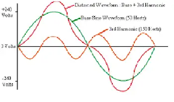
This is the source of most harmonic distortion in a power system. Figure 1 illustrates that any periodic, distorted waveform can be expressed as a sum of sinusoids. When a waveform is ideal from one cycle to the next, it can be represented as a sum of pure sine waves in which the frequency of each sinusoid is an integer multiple of the fundamental frequency of the distorted wave. This multiple is called a harmonic of the fundamental, hence the name of this subject matter. The sum of sinusoids is referred to as a Fourier series, named after the great mathematician who discovered the concept. Nonlinear loads like VFDs and arc furnaces can affect grounding; learn more in our guide to Electrical Grounding.


Fig. 1. Current distortion caused by nonlinear resistance


Voltage and Current Distortion

The term "harmonics" is often used by itself without further qualification. Generally, it could mean one of the following three:

  1. The harmonic voltages are too great (the voltage is too distorted) for the control to properly determine firing angles.

  2. The harmonic currents are too great for the capacity of some devices in the power supply system, such as transformers, and the machine must be operated at a lower than rated power.

  3. The harmonic voltages are too great because the harmonic currents produced by the device are too great for the given system condition.

Clearly, there are separate causes and effects for voltages and currents, as well as some relationship between them. Thus, the term harmonics by itself is inadequate to describe a problem definitively. Nonlinear loads appear to be sources of harmonic current, injecting harmonic currents into the power system. For nearly all analyses, it is sufficient to treat these harmonic-producing loads simply as current sources. There are exceptions to this as described later.


Fig 2. Harmonic currents flowing through the system impedance result in harmonic voltages at the load.

Voltage distortion is the result of distorted currents passing through the linear, series impedance of the power delivery system, as illustrated in Fig. 2. Although assuming that the source bus is ultimately a pure sinusoid, there is a nonlinear load that draws a distorted current. The harmonic currents passing through the system's impedance cause a voltage drop for each harmonic. This results in voltage harmonics appearing at the load bus. The amount of voltage distortion depends on the impedance and the current. Assuming the load bus distortion stays within reasonable limits (e.g., less than 5%), the amount of harmonic current produced by the load is generally constant.

While the load current harmonics ultimately cause voltage distortion, it is worth noting that the load has no control over the voltage distortion. The same load put in two different locations on the power system will result in two different voltage distortion values. Recognition of this fact is the basis for the division of responsibilities for harmonic control that is found in standards such as IEEE Std 519-1992.

  • Control over the amount of harmonic current injected into the system occurs at the end-use application.

  • Assuming the harmonic current injection is within reasonable limits, the control over voltage distortion is exercised by the entity that controls the system impedance, typically the utility.

One must be careful when describing harmonic distortion phenomena, as there are distinct differences between the causes and effects of harmonic voltages and currents. The use of the term harmonics should be qualified accordingly. By popular convention in the power industry, the term is used by itself most of the time when referring to load apparatus, indicating that the speaker is referring to the harmonic currents. When referring to the utility system, the voltages are generally the subject. For systems affected by harmonic-induced overheating, understanding Capacitor Bank applications is essential for voltage support and harmonic filtering. For in-depth harmonic analysis, explore our guide to using a Power Quality Analyzer to identify waveform distortion and power anomalies.


Related Articles


View more

What is the Electricity Demand In Canada?

Electricity demand Canada drives load forecasting, grid reliability, peak demand management, renewable integration, and capacity planning across provinces, informing energy consumption trends, transmission constraints, demand response programs, and ISO market operations.


What Is Electricity Demand Canada?

It is the national electrical load across sectors guiding forecasting, grid planning, and reliability.

✅ Provincial load profiles and peak diversity analysis

✅ Demand response and time-of-use optimizing peak loads

✅ Transmission constraints and capacity expansion planning


Electricity Demand in Canada will continue to put, in the longer term, upward pressure on prices for consumers in both regulated and restructured or deregulated markets. For context, market fundamentals and policy design both shape electricity prices across provinces today, influencing bills over time.

These dynamics play out within an integrated electric power system that balances reliability, affordability, and decarbonization goals.

These pricing impacts will be felt due to the cost of developing new generation and transmission facilities in order to replace ageing infrastructure and due to the increased use of renewable sources of generation (e.g., wind, solar, biomass). Continued strength of oil and gas prices are expected to keep electricity prices higher in regions that rely on natural gas and oil products as input fuels for power generation. Understanding the mix of hydro, wind, solar, nuclear, and gas requires a grasp of how electricity is generated across Canada’s grid components.

With the exception of Ontario (due to its large summer seasonal air conditioning requirement for electricity demand, Canada is a winter-peaking system and so the highest demand loads usually occur in the winter. However, for provinces that have competitive wholesale markets (e.g. Alberta and Ontario), near-term price pressures could result from the increase in summer cooling demand. Prices could also experience additional upward pressure from fuels used to generate electricity; namely, oil and natural gas. These pressures could be further supported by unusual weather events, unplanned generation outages and transmission system failures. If wholesale price pressures are to be passed on to consumers, the cost impact would likely not be felt immediately. Instead, such costs would need to go through a review process in all provinces and be approved by the energy regulatory board of that respective province. Tight reserve margins can constrain electricity supply during extreme temperature events, amplifying short-term price volatility.

Consumer prices or "rates" vary for several reasons:

In many jurisdictions, the total electricity cost combines generation, transmission, distribution, and rider charges that appear separately on bills.


  • variation in generation costs; prices in hydro-based provinces tend to be lower (e.g., British Columbia, Manitoba and Quebec);
  • customer class (e.g., residential, commercial, industrial);
  • residential rates tend to be higher than commercial and industrial rates;
  • amount of energy consumed in a given period (e.g., rates may vary based on customer consumption);
  • time-of-use pricing (e.g., some consumers have access to time of use meters that show lower charges for electricity during off peak periods);
  • and capability to switch to lower cost fuels (e.g. industrial customers)

Consumers in deregulated provinces can compare plans from an electricity supplier to align contract terms and risk with their usage profile.


Electricity demand Canada in peak periods typically occurs during the winter months, although, at times, Ontario and Quebec experience peak electricity demand in the summer months due to increased use of air conditioning units. Spring and fall tend to be shoulder seasons with lower demand. Seasonal patterns also influence maintenance schedules for electricity generation across provinces, which can tighten supply during cold snaps or heat waves.


Related Articles

View more

Power System Analysis Explained

Power System Analysis enables load flow studies, fault calculations, stability assessment, state estimation, and contingency analysis for grids, integrating SCADA data, protection coordination, and reliability planning to optimize transmission, distribution, and generation performance.


What Is Power System Analysis?

Power System Analysis models grid behavior to ensure stability, reliability, efficiency, and secure operation.

✅ Load flow, short-circuit, and transient stability studies

✅ State estimation, SCADA integration, and contingency analysis

✅ Protection coordination, reliability assessment, and optimization


Power system analysis (PSA) is an essential electrical system component. It helps to ensure that the electrical system operates efficiently, reliably, and safely. Power flow analysis, fault study, stability investigation, renewable energy integration, grid modernization, and optimization techniques are all essential concepts in PSA. As our society continues to rely heavily on electricity, PSA will remain a vital tool for ensuring the stability and reliability of the electrical system. For foundational context on how electricity underpins these studies, see this primer on what electricity is and how it behaves.

One of the critical concepts in PSA is power system modelling. Modelling is creating a mathematical model of the electrical system. This model includes all the system components, such as generators, transformers, transmission lines, and distribution networks. Modelling is essential as it provides a detailed understanding of the system's workings. Engineers commonly begin by drafting a single-line diagram to visualize component interconnections and power paths.

Another critical concept in PSA is power flow investigation, also known as load flow investigation. Power flow analysis calculates the electrical system's voltages, currents, and power flows under steady-state conditions. A power flow study helps determine whether the electrical system can deliver electricity to all the loads without overloading any system component. The results of the power flow investigation are used to plan the system's expansion and ensure that it operates efficiently and reliably. In practice, load-flow outputs are interpreted within the broader context of electric power systems to validate voltage profiles and thermal limits.

Fault study is another crucial component of PSA. A fault study is a process of analyzing the system's behaviour during a fault condition. This needs a short circuit analysis. A fault is abnormal when the system has a short or open circuit. A fault study helps to determine the fault's cause and develop strategies to prevent or mitigate the effects of faults in the future.

Stability investigation is also an important aspect of PSA. Stability investigation is the process of analyzing the system's behaviour under dynamic conditions. For example, the system is subject to dynamic disturbances, such as sudden load or generator output changes, which can cause instability. Stability investigation helps ensure the system can withstand these disturbances and operate reliably.

The transient investigation is another key concept in PSA. The transient study analyzes the electrical system's behaviour during transient conditions, such as switching operations or lightning strikes. A brief investigation helps ensure the system can withstand these transient conditions and operate reliably.

Renewable energy integration is an emerging concept in PSA. As more renewable energy sources, such as wind and solar power, are integrated into the energy system, PSA becomes increasingly essential to ensure the stability and reliability of the electrical system. Understanding how generation mixes are formed benefits from a primer on how electricity is generated across thermal, hydro, and renewable technologies.

Grid modernization is also a crucial aspect of PSA. As the system ages, it becomes increasingly important to modernize the grid to ensure that it can meet the demands of modern society. Therefore, PSA is used to develop strategies to modernize the grid and ensure it operates efficiently, reliably, and safely. Many modernization roadmaps align with the evolving architecture of the electricity grid as utilities adopt automation, advanced metering, and distributed resources.

Finally, protection coordination and optimization techniques are essential components of PSA. Protection coordination involves developing strategies to protect the electrical system from faults and other abnormal conditions. Optimization techniques involve developing strategies to optimize the system's operation and ensure it operates efficiently and reliably. Because reactive power and losses affect dispatch, monitoring and improving power factor can materially enhance system efficiency.


What is power system analysis, and why is it important?

PSA analyzes the electrical system to ensure it operates efficiently, reliably, and safely. Therefore, it is crucial to identify potential problems before they occur and develop strategies to prevent or mitigate the effects of these problems. In addition, PSA is important because it helps ensure that the electrical system can meet the demands of modern society, which relies heavily on electricity.


How is power flow analysis performed?

Power flow analysis, or load flow analysis, is performed using a mathematical model. The model includes all the power system components, such as generators, transformers, transmission lines, and distribution networks. A power flow study calculates the electrical system's voltages, currents, and power flows under steady-state conditions. The results of the power flow investigation are used to plan the electrical system's expansion and ensure that it operates efficiently and reliably. These studies also quantify reactive power behavior, making concepts like what power factor is directly applicable to planning and operations.


What is fault analysis, and how is it used?

Fault analysis is analyzing the system's behaviour during a fault condition. A fault is abnormal when the system has a short or open circuit. A fault study is used to determine the fault's cause and develop strategies to prevent or mitigate the effects of faults in the future. Fault analysis is crucial in ensuring the safety and reliability of the electrical system.


What are the different stability study techniques used?

Several stability investigation techniques are used in PSA to measure transient, small-signal, and voltage stability. Transient stability is used to analyze the behaviour of the distribution under dynamic conditions, such as sudden changes in load or generator output. Small-signal stability measurement analyzes the system's behaviour under small disturbances. Finally, voltage stability measurement is used to analyze the system's behaviour under steady-state conditions and determine the system's voltage limits.


How does renewable energy integration affect power system analysis?

Renewable energy integration is an emerging concept in PSA. As more renewable energy sources, such as wind and solar power, are integrated into the electrical system, PSA becomes increasingly essential to ensure the stability and reliability of the system. Renewable energy sources are intermittent, which can cause fluctuations in the system. PSA is used to develop strategies to integrate renewable energy sources into the system while ensuring its stability and reliability.


What are the challenges of grid modernization, and how does power system analysis help overcome them?

Grid modernization is a crucial aspect of PSA. As the system ages, it becomes increasingly important to modernize the grid to ensure that it can meet the demands of modern society. Grid modernization involves upgrading the system to incorporate new technologies, such as smart grid technologies and renewable energy sources. The challenges of grid modernization include the need for new infrastructure, the integration of new technologies, and new regulatory frameworks. PSA is used to develop strategies to overcome these challenges and to ensure that the electrical system operates efficiently, reliably, and safely.


How can optimization techniques improve system efficiency and reliability in power system analysis?

Optimization techniques can be used in PSA to improve system efficiency and reliability. These techniques involve developing strategies to optimize the system's operation and ensure it operates efficiently and reliably. For example, optimization techniques can determine the optimal generation and transmission of power, improve load forecasting, and develop strategies to reduce energy consumption. PSA is crucial in developing and implementing these optimization techniques, which help improve the electrical system's overall efficiency and reliability, leading to a more sustainable and cost-effective electrical power system.


Related Articles

View more

Sign Up for Electricity Forum’s Newsletter

Stay informed with our FREE Newsletter — get the latest news, breakthrough technologies, and expert insights, delivered straight to your inbox.

Electricity Today T&D Magazine Subscribe for FREE

Stay informed with the latest T&D policies and technologies.
  • Timely insights from industry experts
  • Practical solutions T&D engineers
  • Free access to every issue

Live Online & In-person Group Training

Advantages To Instructor-Led Training – Instructor-Led Course, Customized Training, Multiple Locations, Economical, CEU Credits, Course Discounts.

Request For Quotation

Whether you would prefer Live Online or In-Person instruction, our electrical training courses can be tailored to meet your company's specific requirements and delivered to your employees in one location or at various locations.