Types of Electricity - Static and Current


Types of electricity include static electricity and current electricity, which flows as direct current (DC) or alternating current (AC). Electricity can be generated from various sources, including solar, wind, and hydro, but all supply either static or current electricity.


What are the Types of Electricity?

There are two types of electricity: Static Electricity and Current Electricity.

Static electricity results from the buildup of electric charges.

✅ Current electricity includes alternating (AC) and direct (DC) flow.

Static Electricity is made by rubbing together two or more objects, creating friction, while Current electricity is the flow of electric charge across an electrical field.


Static Electricity

Static electricity is when electrical charges build up on the surface of a material. It is usually caused by rubbing materials together. The result of a build-up of static electricity is that objects may be attracted to each other or may even cause a spark to jump from one to the other. For Example, rub a balloon on a wool and hold it up to the wall.

Before rubbing, like all materials, the balloons and the wool sweater have a neutral charge. This is because they each have an equal number of positively charged subatomic particles (protons) and negatively charged subatomic particles (electrons). When you rub the balloon with the wool sweater, electrons are transferred from the wool to the rubber because of differences in the attraction of the two materials for electrons. The balloon becomes negatively charged because it gains electrons from the wool, and the wool becomes positively charged because it loses electrons.


Current Electricity

Current is the rate of flow of electrons. The movement of electrons produces it, and it is measured in amperes. Unlike static electricity, current electricity must flow through a conductor, usually copper wire. Electricity is similar to the flow of water in a river. The river flows from one spot to another, and the speed of the current determines the speed at which it moves. With electricity, current is a measure of the amount of energy transferred over a period of time. That energy is referred to as an electron flow. One of the results of the current is the heating of the conductor. When an electric stove heats up, it's because of the flow of current.

There are various sources of current electricity, including the chemical reactions that occur in a battery. The most common source is the generator. A simple generator produces electricity when a coil of copper turns inside a magnetic field. In a power plant, electromagnets spinning inside many coils of copper wire generate vast quantities of electricity.

There are two main kinds of electric current. Direct (DC) and Alternating (AC). It's easy to remember. Direct current is similar to the energy you obtain from a battery. Alternating current is like the plugs in the wall. The big difference between the two is that DC is a flow of energy, while AC can turn on and off. AC reverses the direction of the electrons.


Related Articles


Related News

Watthour Meter Explained

A watthour meter measures electrical energy consumption in kilowatt-hours (kWh) for residential, commercial, and industrial applications, ensuring accurate billing, energy management, and compliance with utility standards.


What is a Watthour Meter?

✅ Measures total electrical energy in kilowatt-hours (kWh) over time

✅ Supports accurate billing, energy monitoring, and demand analysis

✅ Used in residential, commercial, and industrial revenue metering


Advancements in Watthour Meter Technology and Energy Measurement

Watthour meter technology plays a crucial role in modern electrical engineering and maintenance by providing accurate measurement and monitoring of energy consumption. These devices are indispensable for managing energy efficiency, optimizing power distribution, and ensuring compliance with regulatory standards. For electrical professionals, understanding how they operate and are maintained is essential to minimize energy losses and enhance the reliability of electrical systems. With the growing demand for precise energy data in both residential and industrial applications, staying informed about advancements in watthour meter technology is more important than ever. Understanding how a watthour is calculated helps clarify how a watthour meter tracks total energy usage for accurate billing. 


How Induction Type Single Phase Watt Hour Meters Work

Induction type meters, commonly used as single phase watt hour meters, provide accurate measurement of electrical energy consumption in residential and small commercial installations.

Your electric utility is not too interested in how much power you're consuming for one ap­pliance or even how much power a single household is drawing at any given time. By far the greater concern is the total energy that is used over a day, a week, a month or a year. Electrical energy is measured in watt-hours or, more commonly for utility pur­poses, in kilowatt-hours (kWh). The device that measures this consumption is the watt-hour meter or kilowatt-hour meter. For a deeper understanding of the units used in metering, see our guide on electrical energy and how it is measured in kilowatt-hours.

The most common method for measuring electrical energy is by using a small elec­tric motor device, whose speed depends on the current, and thereby on the power at a constant voltage. The number of turns of the motor shaft, in a given length of time, is di­rectly proportional to the number of watt hours consumed. The motor is placed at the point where the utility wires enter the house, apartment or building. This is usually at a point where the voltage is 234 V. This is split into some circuits with 234 V, for heavy-duty appliances such as the oven, washer and dryer, and the general household circuits for lamps, clock radios and television sets. The principles behind watthour meters are closely tied to basic electricity and the relationship between active power and time.


Understanding the Spinning Disk in Electromechanical Watthour Meters

You've surely seen the little disk in the utility meter going around and around, sometimes fast, other times slowly. Its speed depends on the power you're using. The total number of turns of this little disk, every month, determines the size of the bill you will get, as a function also, of course, of the cost per kilowatt hour for electricity.

Kilo-watt-hour meters count the number of disk turns by means of geared, rotary drums or pointers. The drum-type meter gives a direct digital readout. The pointer type has several scales calibrated from 0 to 9 in circles, some going clockwise and others go­ing counterclockwise. Mechanical and electronic meters both rely on the concepts of electrical resistance and current to provide precise readings.


How to Read a Pointer-Type Watthour Meter Accurately

Reading a pointer-type utility meter is a little tricky because you must think in whatever direction (clockwise or counterclockwise) the scale goes. An example of a pointer-type utility meter is shown in Fig. 3-11. Read from left to right. For each little meter, take down the number that the pointer has most recently passed. Write down the rest as you go. The meter in the figure reads 3875 kWh. If you want to be really pre­cise, you can say it reads 3875-1/2 kWh. To place watt hour metering in historical context, explore our history of electricity page and learn how early meters evolved into today’s advanced devices.


Fig. 3-11 An example of a utility kilo-watthour meter. The reading is a little more than 3875 kWh.


Related Articles


View more

Electrical Units Explained

Electrical units measure various aspects of electricity, such as voltage (volts), current (amperes), resistance (ohms), and power (watts). These standard units are crucial in electrical engineering, circuit design, energy monitoring, and ensuring the safe operation of electrical systems.


What are Electrical Units?

Electrical units are standardized measures used to quantify electrical properties in circuits and systems.

✅ Measure voltage, current, resistance, power, and energy

✅ Used in electrical engineering, testing, and design

✅ Support safe and efficient electrical system operations

Electrical units are standardized measurements that describe various aspects of electricity, such as current, voltage, resistance, and power. These units, like amperes for current and volts for voltage, help quantify the behavior and interaction of systems. By understanding electrical units, professionals can assess performance, design circuits, and ensure safety across different applications. These electrical units play a crucial role in the functioning of everything from household appliances to industrial machinery, making them fundamental in engineering and everyday technology.

In common electricity systems, various electrical units of measure, such as magnetic field, are used to describe how electricity flows in the circuit. For example, the unit of resistance is the ohm, while the unit of time is the second. These measurements, often based on SI units, help define the phase angle, which describes the phase difference between current and voltage in AC circuits. Understanding these electrical units is critical for accurately analyzing performance in both residential and industrial applications, ensuring proper function and safety.


Ampere

The ampere is the unit of electric current in the SI, used by both scientists and technologists. Since 1948, the ampere has been defined as the constant current that, if maintained in two straight, parallel conductors of infinite length and negligible circular cross-section, and placed one meter apart in a vacuum, would produce between these conductors a force equal to 2 × 10^7 newtons per meter of length. Named for the 19th-century French physicist André-Marie Ampere, it represents a flow of one coulomb of electricity per second. A flow of one ampere is produced in a resistance of one ohm by a potential difference of one volt. The ampere is the standard unit of electric current, playing a central role in the flow of electricity through electrical circuits.


Coulomb

The coulomb is the unit of electric charge in the metre-kilogram—second-ampere system, the basis of the SI system of physical electrical units. The coulomb is defined as the quantity of electricity transported in one second by a current of one ampere. Named for the I8th—I9th-century French physicist.


Electron Volt

A unit of energy commonly used in atomic and nuclear physics, the electron volt is equal to the energy gained by an electron (a charged particle carrying one unit of electronic charge when the potential at the electron increases by one volt. The electron volt equals 1.602 x IO2 erg. The abbreviation MeV indicates 10 to the 6th (1,000,000) electron volts, and GeV, 10 to the 9th (1,000,000,000). For those managing voltage drop in long circuits, we provide a helpful voltage drop calculator and related formulas to ensure system efficiency.


Faraday

The Faraday (also known as the Faraday constant) is used in the study of electrochemical reactions and represents the amount of electric charge that liberates one gram equivalent of any ion from an electrolytic solution. It was named in honour of the 19th-century English scientist Michael Faraday and equals 6.02214179 × 10^23 coulombs, or 1.60217662 × 10^-19 electrons.


Henry

The henry is a unit of either self-inductance or mutual inductance, abbreviated h (or hy), and named for the American physicist Joseph Henry. One henry is the value of self-inductance in a closed circuit or coil in which one volt is produced by a variation of the inducing current of one ampere per second. One henry is also the value of the mutual inductance of two coils arranged such that an electromotive force of one volt is induced in one if the current in the other is changing at a rate of one ampere per second.


Ohm

The unit of resistance in the metre-kilogram-second system is the ohm, named in honour of the 19th-century German physicist Georg Simon Ohm. It is equal to the resistance of a circuit in which a potential difference of one volt produces a current of one ampere (1 ohm = 1 V/A); or, the resistance in which one watt of power is dissipated when one ampere flows through it. Ohm's law states that resistance equals the ratio of the potential difference to current, and the ohm, volt, and ampere are the respective fundamental electrical units used universally for expressing quantities. Impedance, the apparent resistance to an alternating current, and reactance, the part of impedance resulting from capacitance or inductance, are circuit characteristics that are measured in ohms. The acoustic ohm and the mechanical ohm are analogous units sometimes used in the study of acoustic and mechanical systems, respectively. Resistance, measured in ohms, determines how much a circuit resists current, as explained in our page on Ohm’s Law.


Siemens

The siemens (S) is the unit of conductance. In the case of direct current (DC), the conductance in siemens is the reciprocal of the resistance in ohms (S = amperes per volt); in the case of alternating current (AC), it is the reciprocal of the impedance in ohms. A former term for the reciprocal of the ohm is the mho (ohm spelled backward). It is disputed whether Siemens was named after the German-born engineer-inventor Sir William Siemens(1823-83) or his brother, the engineer Werner von Siemens (1816-92).


Volt

The unit of electrical potential, potential difference, and electromotive force in the metre—kilogram—second system (SI) is the volt; it is equal to the difference in potential between two points in a conductor carrying one ampere of current when the power dissipated between the points is one watt. An equivalent is the potential difference across a resistance of one ohm when one ampere of current flows through it. The volt is named in honour of the I8th—I9th-century Italian physicist Alessandro Volta. Ohm's law defines these electrical units, where resistance equals the ratio of potential to current, and the respective units of ohm, volt, and ampere are used universally for expressing electrical quantities. Energy consumption is measured in kWh, or kilowatt-hours. Explore how devices like ammeters and voltmeters are used to measure current and voltage across components. To better understand how voltage is measured and expressed in volts, see our guide on what is voltage.


Watt

The watt is the unit of power in the SI equal to one joule of work performed per second, or to 1/746 horsepower. An equivalent is the power dissipated in a conductor carrying one ampere of current between points at a one-volt potential difference. It is named in honour of James Watt, British engineer and inventor. One thousand watts equals one kilowatt. Most electrical devices are rated in watts. Learn how a watt defines power in electrical systems and its relationship to volts and amperes through Watts' Law.


Weber

The weber is the unit of magnetic flux in the SI, defined as the amount of flux that, linking a circuit of one turn (one loop of wire), produces in it an electromotive force of one volt as the flux is reduced to zero at a uniform rate in one second. It was named in honour of the 19th-century German physicist Wilhelm Eduard Weber and equals 10 to the 8th maxwells, the unit used in the centimetre—gram—second system.

Related Articles


View more

Electricity Grid - T&D

Electricity grid infrastructure delivers power through transmission lines, substations, and smart grid controls, balancing voltage and frequency, integrating renewable energy, enabling demand response, improving reliability, and supporting utilities with real-time monitoring and load management.


What Is the Electricity Grid?

A network of transmission, distribution, and control systems that delivers reliable electrical power to consumers.

✅ Transmits high-voltage power from plants to local networks

✅ Steps down voltage at substations for safe distribution

✅ Integrates renewables with smart grid and demand response


The electricity grid is a complex and essential component of modern society. It provides the power necessary to operate homes, businesses, and industries, and it is constantly evolving to meet the demands of a changing world. From power generation to distribution, transmission lines to load balancing and renewable energy integration, every component is critical in ensuring we can access reliable and affordable energy whenever needed. For a broader primer, resources such as electric power systems outline how these elements interconnect in practice.

At its core, the grid is a system that connects power generation facilities to consumers through transmission lines and distribution systems. It is designed to move electricity from where it is generated to where it is needed, whether in a residential home or a large industrial facility. The term "grid" refers to the interconnectedness of these systems, which allows power to flow from one location to another as needed. The federal energy regulatory commission ferc regulates the grid.

In North America, the transmission and distribution (T&D) grid is managed by federal, state, provincial, and territorial agencies. The grid is divided into various regions, each with its grid operator responsible for ensuring reliable and efficient operation within their respective jurisdiction. For instance, Canada's power delivery network is divided into four main regions: Western Canada, Ontario, Quebec, and the Atlantic region. Similarly, the United States' electricity grid is divided into three major interconnected systems: the Eastern Interconnection, Western Interconnection, and the Electric Reliability Council of Texas (ERCOT) system. Each region's grid operator works closely with neighbouring grid operators to ensure a seamless flow of electrical power across the interconnected grid, even during periods of high demand or unexpected outages.

The power delivery network can be broken down into three main components: power generation, transmission, and distribution. Power generation facilities can take many forms, including coal-fired, natural gas, nuclear, and renewable energy sources such as wind and solar. These facilities generate electrical power transmitted over high-voltage transmission lines to substations, where the voltage is lowered for distribution to homes and businesses through a network of distribution lines. For those new to supply technologies, overviews of how electricity is generated cover conventional and renewable pathways.

Transmission lines are a critical component of the T&D system, which deliver and produce electricity at higher voltages. T&D provides the means to move large amounts of electrical power over long distances. These lines are typically made of high-strength steel or aluminum and span hundreds of miles. They are also designed to be highly resilient to extreme weather events such as hurricanes, tornadoes, and ice storms. Understanding ratings, capacity, and losses draws on electricity power fundamentals that inform planning and operations.

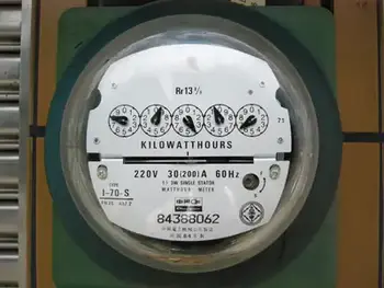
The distribution system is the final component of the power grid, responsible for delivering electrical power directly to homes and businesses. This system includes transformers, power lines, and meters, which work together to regulate power flow to individual consumers. The distribution system also includes local power generation facilities, such as rooftop solar panels and small-scale wind turbines, which can supplement the power provided by the grid. To see how fuel mixes influence local grids, summaries of sources of electricity highlight regional differences.

As the world increasingly relies on electrical power, there is a growing need to modernize and upgrade the power delivery network to meet the demands of the 21st century. One approach to this is the development of a smart grid, which uses advanced sensors, communication networks, and analytics to optimize the flow of power and improve reliability. Another approach is the integration of renewable energy sources such as wind and solar into the grid, which can reduce greenhouse gas emissions and improve grid resilience. Advanced planning and forecasting increasingly leverage power system analysis to evaluate contingencies and optimize investments.

Load balancing is another critical function, ensuring that real-time power generation and consumption are matched. This is accomplished through a combination of forecasting, automated control systems, and energy storage facilities such as batteries and pumped hydroelectric storage. In flexible markets, insights into electricity generation help operators schedule resources effectively.

Reliability and resilience are also crucial factors in its overall performance. The grid must be designed to withstand extreme weather events and other disruptions, such as cyberattacks or equipment failures. This requires a combination of robust engineering and effective emergency response planning.


What is an electricity grid, and how does it work?

A T&D system is a complex network of power generation facilities, transmission lines, and distribution systems that work together to ensure reliable and affordable energy is available to consumers. At its core, the grid is a system that connects power generation facilities to consumers through transmission lines and distribution systems. It is designed to move electrical power from where it is generated to where it is needed, whether in a residential home or a large industrial facility. The grid uses high-voltage transmission lines to move electrical power over long distances, then lowers the voltage through transformers for distribution to homes and businesses. For foundational clarity, a concise explainer on what electricity is helps connect basic concepts to grid operations.


What is the difference between the transmission and distribution systems?

The transmission system is responsible for moving large amounts of electrical power over long distances at high voltages. This is accomplished through a network of high-voltage transmission lines and substations spanning hundreds of miles. The distribution system delivers electrical power directly to homes and businesses at lower voltages. This system includes transformers, power lines, and meters, which work together to regulate the flow of electricity to individual consumers.


How is renewable energy integrated?

Renewable energy sources such as wind and solar are integrated into the T&D system through a process called interconnection. This involves connecting the renewable energy source to the grid through a substation and transformer, ensuring that the energy generated can be transmitted to consumers. Renewable energy sources can also be connected to the grid through distributed generation, where energy is generated on-site at the point of consumption, such as through rooftop solar panels.


What are the challenges associated with maintaining the reliability and resilience of the T&D system?

Maintaining reliability and resilience is a complex task requiring robust engineering and effective emergency response planning. Some of the challenges associated with this include extreme weather events, cyberattacks, equipment failures, and natural disasters. In addition, as the grid becomes more reliant on renewable energy sources, new challenges may arise related to load balancing and energy storage.


What is a smart grid, and how does it differ from a traditional T&D system?

A smart grid is a modernized version of the traditional T&D system that uses advanced sensors, communication networks, and analytics to optimize the flow of electrical power and improve reliability. Unlike a traditional T&D system, designed to move electrical power from power plants to consumers, a smart grid enables two-way communication between consumers and the grid. This allows for greater control and flexibility in managing energy usage and improved efficiency and reliability.


How can energy storage be used to support the T&D system?

Energy storage can be used to support the T&D system in several ways. One essential function is to provide backup power in the event of a blackout or other disruption to the grid. Energy storage can also help balance the load on the grid, ensuring that power generation and consumption are matched in real-time. In addition, energy storage can help integrate renewable energy sources into the grid by storing excess energy for use during times of low generation.


What is grid modernization, and why is it important for the future of the T&D system?

Grid modernization refers to upgrading and improving the T&D system to meet the demands of a changing world. This may involve the development of a smart grid, the integration of renewable energy sources, and the deployment of advanced sensors and control systems. Grid modernization is important for the future of the T&D system because it will enable greater efficiency, reliability, and sustainability while ensuring that the grid is resilient to emerging threats and challenges.


Related Articles

View more

Electricity Power Explained

Electricity power underpins voltage, current, and wattage in generation, transmission, and distribution across the grid, integrating AC/DC systems, transformers, generators, load management, power factor correction, and renewable energy for efficient, reliable supply.


What Is Electricity Power?

Electricity power is energy transfer rate: voltage times current, yielding watts in AC/DC systems.

✅ P = V * I; apparent, real, reactive power relationships

✅ Power factor improves efficiency and reduces I^2R losses

✅ Transformers step voltage for transmission efficiency


The make up of the electricity power sector has been in transition over recent history. In most provinces, there has been a transition from traditional electric utilities (which are mostly provincially-owned crown corporations) to private generation, transmission and distribution assets. For context, industry overviews such as electricity generation in Canada outline how policy and market structures influence capacity additions today.

In 2014, Canadian eutilities and industrials generators produced more than 639 terawatt hours of electricity. When it comes to hydroelectric power, Canada is the world's second largest producer. Hydroelectricity accounts for 59.3 per cent of Canada’s supply. Other energy sources that contribute to the transfer of energy include: coal, uranium, natural gas, petroleum and non-hydro renewable energy sources. About 67 per cent of Canada’s energy comes from renewable sources like wind, solar and hydroelectric power stations and 82% from non-greenhouse gas emitting sources. A breakdown of major fuels is available through sources of electricity for readers comparing provincial mixes.

Hydropower output is intrinsically linked to water availability and operations, and resources on water and electricity explain how hydrology and infrastructure shape generation profiles.

In 2014, almost 59 terawatt hours of electricity exported to the USA, while about 13 terawatt hours was imported from the United States. These trade patterns reflect how provinces balance load and generation portfolios, as noted in discussions of electricity supply dynamics under varying market conditions.

Canada's industrial sector is responsible for the largest share of electricity demand because there are a number of energy-intensive industrial activities like mining, oil and gas production, pulp and paper production, and other primary industry uses. Residential and commercial sectors consume much smaller quantities of electricity for lighting (light bulb), heating, and communications. Detailed consumption patterns can be explored in Canada's electricity demand by sector and region.

R&D programs aimed at maintaining the operating capability of the nation’s existing nuclear power plants and developing the next generation of nuclear technologies. Nuclear energy is the world’s largest source of emission-free electricity power. The Nuclear Energy program is working to develop cost-efficient technologies that further enhance nuclear safety, minimize the generation of nuclear waste, and further reduce the risk of proliferation. Within the broader generation portfolio, resources like nuclear are profiled in guides on how electricity is generated across different technologies.

To meet the rising demand of the 21st century, significant improvements in America’s electric system are necessary. Blackouts serve as a powerful reminder of the critical role electricity plays in the everyday lives of people.


Voltages, currents, power energy

When it comes to electric current, electrical voltage, electric circuit dynamics and energy powers, all rely on the flow of the electron. What this means is that power voltage feeds loads, solid state power load devices, and other loads that need electric power. Electric power is the rate at which that power is measured in watts or voltage in volts. There are various forms of energy measured in si unit: apparent power, reactive power, ac power, real power in watts, etc. For a refresher on fundamental concepts and terminology, see what is electricity to connect these quantities with practical applications.

Electrical Engineers and Scientists alike seek common views in order to develop new technologies for the storage of energy and the transmission of electric potential through power circuits that will contribute to energy efficiency of the electric industry. For instance, the copper wires used in typical transmission lines lose a percentage of the electricity passing through them because of resistance over long distances, which causes the wires to heat up. But "superconducting" materials have no resistance, and if they are used to transmit electricity in the future, very little of the electricity will be lost.


Related Articles

View more

Inductive Load Explained

An inductive load is common in electrical systems and can significantly impact power quality. Understanding inductive and resistive loads, as well as their impact on the quality of your electricity, is essential for designing and operating an effective electrical system.


What is an Inductive Load?

An inductive load is an electrical device or component that consumes active power while storing energy in a magnetic field due to inductance.

✅ Common in motors, transformers, and relays

✅ Impacts power factor and reactive power demand

✅ Requires compensation with capacitors for efficiency


Power Quality Analysis Training

Power Factor Training

Request a Free Power Quality Training Quotation

In power systems, an inductive load affects the flow of electrical current through conductors, creating conditions that may necessitate careful monitoring. A hot wire and a neutral wire must be properly balanced to avoid hazards, while ground fault circuit interrupters play a vital role in protecting against dangerous faults. Recognizing early signs of a short circuit, such as tripped breakers or overheating, is essential for maintaining system reliability and preventing equipment damage.


How does it affect Power Quality?

Inductive load affects power quality by introducing reactive power into an electrical system. Reactive power is the power that an IL consumes but does not convert into useful work. This can cause a decrease in the overall PF of the system. A low power factor (PF) can result in increased losses, decreased efficiency, and increased power source costs. Additionally, inductive loads can cause voltage drops and fluctuations, which can affect the operation of other electrical devices. Because inductive devices consume reactive power, engineers often use the apparent power formula to calculate their influence on system demand.


What are the types of inductive load?

There are several types of inductive loads, including electric motors, transformers, and heating elements. Electric motors are used in a wide range of applications, from household appliances to industrial machinery. Transformers are used to step up or step down voltage in electrical systems. Heating elements, such as those used in ovens and stovetops, rely on the inductive heating effect to generate heat. One way to minimize the effect of inductive loads on power factor is by installing an automatic power factor controller.


Common examples include:

  • Electric motors: ILs are commonly found in electric motors used in various appliances, such as washing machines, refrigerators, and air conditioners. Electric motors require electrical energy to create a magnetic field that rotates the motor's shaft, resulting in a lagging current.

  • Transformers are devices used to transfer electrical energy from one circuit to another through electromagnetic induction. They are commonly used in distribution systems to step up or step down the voltage to the required level.

  • Fluorescent lights use a ballast to regulate the flow of electricity to the lamp. The ballast contains an IL that helps regulate the electrical current and voltage to the light.

  • Welding equipment: Welding equipment, such as arc welders, use ILs to create a strong magnetic field that is used to generate the heat required for welding.

  • Induction cooktops: Induction cooktops use magnetic fields to create heat, and this requires the use of ILs to generate the magnetic field.

  • Speakers: Speakers use ILs in their voice coils to create a magnetic field that moves the speaker cone and produces sound.

It's essential to understand the different types of electrical load in order to manage consumption and ensure the efficient operation of electrical systems. Different types of loads require different management strategies, and PF correction may be necessary to optimize energy efficiency. Accurate evaluation of an inductive circuit often requires an apparent power calculator to measure kVA, kVAR, and kW contributions.


Frequently Asked Questions

How can you measure the Power Factor of an inductive load?

The PF of an IL can be measured using a PF meter or a digital multimeter. These devices measure the PF by comparing the real power (the power that is actually converted into useful work) to the apparent power (the total power consumed by the load). The PF is then calculated as the ratio of the real power to the apparent power. Inductive devices are often compared with a resistive load, which converts all energy into heat or light without reactive power.


What is the difference between a resistive and an inductive load?

A resistive load is a type of electrical load that converts electrical energy into heat or light, such as an incandescent light bulb or a resistor. A resistive load has a PF of 1, meaning that all of the electricity consumed by the load is converted into useful work. In contrast, an IL stores energy in a magnetic field and has a PF of less than 1. This means that some of the electricity consumed by the load is not converted into useful work.


What are some common examples?

Some common examples of ILs include electric motors, transformers, and fluorescent lights. These loads are found in a wide range of applications, from household appliances to industrial machinery.


How can you reduce the impact of inductive load on a system?

There are several ways to reduce the impact of ILs on an electrical system. One way is to improve the PF of the system by adding PF correction capacitors. These capacitors can help offset the reactive electricity consumed by ILs, thereby increasing the PF of the system. Another approach is to utilize soft starters or variable frequency drives with electric motors, which can reduce inrush current and minimize voltage fluctuations. Finally, using a high-efficiency supply or reducing the number of ILs in a system can also help reduce the impact of ILs on PQ. To balance inductive and capacitive elements, engineers apply power factor correction techniques that restore efficiency and reduce system losses.

By understanding the different types, measuring the PF, and reducing its impact on a system, electrical engineers can design and operate systems that are more efficient, reliable, and cost-effective.

It's worth noting that they are not the only types of electrical loads that can impact PQ. Capacitive loads, such as capacitors and fluorescent lights, can also introduce reactive power into a system. Additionally, purely resistive loads, such as resistors and incandescent light bulbs, do not introduce reactive power but can still affect PQ in other ways, including the generation of heat.

Understanding the different types of electrical loads and their impact on PQ is essential for designing and operating efficient and reliable electrical systems. While they can introduce reactive power and affect PF, there are ways to minimize their impact and improve PQ. By taking a holistic approach to electrical system design and operation, engineers can create systems that meet the needs of their users while minimizing costs and maximizing efficiency. Since inductive loads influence reactive currents, using the reactive power formula helps quantify their effect on power system design and operation.


Related Articles


View more

Tidal Electricity From Wave Action

Tidal electricity converts predictable ocean tides into renewable energy using tidal turbines, barrages, and lagoons, delivering stable baseload marine power, efficient grid integration, low carbon emissions, and robust reliability through advanced hydrodynamics and power electronics.


What Is Tidal Electricity?

Tidal electricity generates grid power from ocean tides via turbines or barrages, providing predictable, low-carbon output.

✅ Uses tidal stream turbines, barrages, and lagoons

✅ Predictable output enhances grid stability and capacity planning

✅ Power electronics enable efficient conversion and grid integration


Tidal electricity is obtained by utilizing the recurring rise and fall of coastal waters. Marginal marine basins are enclosed with dams, making it possible to create differences in the water level between the ocean and the basins. The oscillatory flow of water filling or emptying the basins is used to drive hydraulic turbines which propel wave generators. As a specialized branch of hydroelectricity, tidal schemes convert predictable water level differences into dispatchable power.

The cyclical movement of seawater exemplifies how water electricity systems depend on fluid dynamics and site geometry.

Large amounts of wave generation could be developed in the world's coastal regions having tides of sufficient range, although even if fully developed this would amount to only a small percentage of the world's potential hydroelectric power. In global electricity production portfolios, tidal energy typically plays a niche role alongside other renewables.

Because installations are coastal and infrastructure-intensive, they can contribute to regional green electricity targets with long service lives.

It is produced by turbines operated by tidal flow. Many ideas for harnessing the tides were put forward in the first half of the 20th century, but no scheme proved technically and economically feasible until the development by French engineers of the plan for the Rance power plant in the Gulf of Saint-Malo, Brittany, built 1961–67. A dam equipped with reversible turbines (a series of fixed and moving blades, the latter of which are rotated) permits the tidal flow to work in both directions, from the sea to the tidal basin on the flood and on the ebb from the basin to the sea. The Rance plant has 24 power units of 10,000 kilowatts each; about seven-eighths of the power is produced on the more controllable ebb flow. The sluices fill the basin while the tide is coming in and are closed at high tide. Emptying does not begin until the ebb tide has left enough depth of fall to operate the turbines. Conversely, the turbines are worked by the incoming tide to the basin. With reversible bulb turbines, both ebb and flood flows generate electricity with high capacity factors during spring tides.

Compared with windmills for electricity, tidal turbines benefit from dense water flow that yields steadier torque.

The Soviet Union completed construction in 1969 of a plant of about 1,000 kilowatts on the White Sea. Other sites of interest for tidal power plants include the Bay of Fundy in Canada, where the tidal range reaches more than 15 m (49 feet). Although large amounts of power are available from the tides in favourable locations, this power is intermittent and varies with the seasons. Grid planners often pair tidal plants with storage and flexible resources used in electricity windmill operations to smooth variability.


Related Articles

View more

Sign Up for Electricity Forum’s Newsletter

Stay informed with our FREE Newsletter — get the latest news, breakthrough technologies, and expert insights, delivered straight to your inbox.

Electricity Today T&D Magazine Subscribe for FREE

Stay informed with the latest T&D policies and technologies.
  • Timely insights from industry experts
  • Practical solutions T&D engineers
  • Free access to every issue

Live Online & In-person Group Training

Advantages To Instructor-Led Training – Instructor-Led Course, Customized Training, Multiple Locations, Economical, CEU Credits, Course Discounts.

Request For Quotation

Whether you would prefer Live Online or In-Person instruction, our electrical training courses can be tailored to meet your company's specific requirements and delivered to your employees in one location or at various locations.