Powerline Transformer Reliability at the Distribution Edge
By Howard Williams, Associate Editor
By Howard Williams, Associate Editor
Our customized live online or in‑person group training can be delivered to your staff at your location.

A powerline transformer governs how reliably electricity reaches end users. When thermal limits, losses, or phase imbalance are misjudged, degradation occurs gradually, leading to voltage instability, overheating, and insulation aging.
Once installed, a powerline transformer operates at the point where grid design assumptions meet unpredictable demand. Load diversity that appears orderly in planning models becomes irregular in service, shaped by seasonal consumption, uneven phase loading, and environmental exposure, which steadily erode operating margins.
Residential feeders introduce sharp peaks and long idle periods. Rural networks amplify cycling stress. Weather, sun exposure, and cooling conditions further influence internal temperature in ways ratings alone do not capture. These factors accumulate quietly, narrowing tolerance long before any visible fault appears.
For utilities, this is why a powerline transformer is not treated as a simple step-down device. It is treated as a reliability boundary—one where small errors in loading assumptions, loss evaluation, or imbalance tolerance compound over decades into service complaints, nuisance interruptions, and shortened asset life.
In service, losses are not abstract efficiency metrics. Core losses are constant regardless of load, while copper losses rise sharply during peak demand. The interaction between these two mechanisms determines internal temperature, which in turn determines insulation life. A unit that appears conservatively sized on paper can still age prematurely if it experiences aggressive cycling.
This behavior is often missed because nameplate ratings imply steady operation, which rarely occurs at the edge of the grid. The mechanisms behind this process are examined in transformer losses, which explain why insulation degradation accelerates long before external damage becomes visible.
Download our FREE Electrical Training Catalog and explore a full range of expert-led electrical training courses.

Once oil temperature routinely exceeds design assumptions, remaining life shortens exponentially. By the time external symptoms appear, the degradation is usually irreversible.
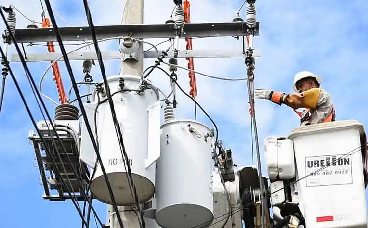
Although the powerline transformer is often described in simple terms, its physical configuration directly influences reliability. Units connected to distribution lines must withstand high voltages on the primary side and deliver a stable output through secondary windings, often under uneven single-phase demand.
Whether pole-mounted on a utility pole or pad-mounted at ground level, cooling performance depends on enclosure design, airflow, and the insulating medium—commonly mineral oil or, in some cases, dry-type construction. Voltage stability is further shaped by tap-changer settings and by how effectively the transformer adjusts voltage as load fluctuates along power lines.
These physical attributes are not neutral details; they determine how well the transformer manages thermal rise, phase imbalance, and long-term voltage regulation within the distribution system.
Whether a transformer is pole-mounted or ground-mounted matters less than how its environment interacts with load. Sun exposure, wind cooling, restricted airflow, soil moisture, and enclosure design all influence heat dissipation. Two identical units installed a few blocks apart can age very differently under the same electrical demand.
These factors are rarely reflected in initial capacity decisions. Engineers who rely solely on kVA ratings often miss how installation context erodes usable margin. Viewing the powerline unit within the broader class of electrical transformers clarifies why identical designs perform inconsistently once deployed.
Transformers rarely fail because they are poorly built. They fail because they are asked to operate for decades in conditions their insulation systems were never sized to endure continuously.
Powerline transformers are especially vulnerable to asymmetry. Residential and mixed-use feeders introduce uneven single-phase loading that can quietly overload one leg while total demand appears acceptable. Voltage instability often originates here, not from insufficient capacity.
Connection configuration determines how forgiving the system is under imbalance. Certain arrangements distribute stress more evenly, while others magnify asymmetry. The practical implications of these choices are described in delta vs wye configurations, which explains why some secondaries tolerate imbalance far better than others.
Ignoring this relationship increases losses, destabilizes voltage, and accelerates aging without triggering immediate protective action.
Powerline transformers almost never fail without warning, but the warnings are subtle. Oil temperature trends, dissolved gas evolution, and infrared hot spots must be interpreted together and over time. A single snapshot rarely tells the truth.
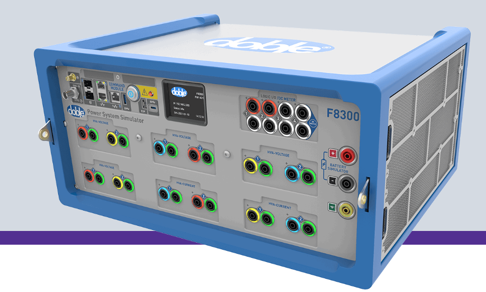
Approaches described in transformer testing emphasize trend analysis rather than pass-fail thresholds. When interpreted correctly, these signals allow intervention years before failure becomes unavoidable.
Equally important is whether the transformer was ever matched to its real duty cycle. Proper transformer sizing aligns thermal limits with actual load behavior, not conservative arithmetic or worst-case assumptions.
At the distribution edge, visibility often comes from surrounding instrumentation rather than the transformer itself. Load imbalance, harmonic contributions, and fault behavior are inferred from external measurements rather than internal sensors.
This is where devices described under current transformers become essential, revealing operating conditions that explain why stress accumulates long before the powerline transformer appears compromised.
Understanding this measurement ecosystem explains why transformer problems are frequently diagnosed indirectly—through feeder instability and customer voltage complaints—rather than at the transformer terminals.
Think you know Utility Transformers? Take our quick, interactive quiz and test your knowledge in minutes.
Explore 50+ live, expert-led electrical training courses –