What is a Transformer?
By William Conklin, Technical Editor
By William Conklin, Technical Editor
Our customized live online or in‑person group training can be delivered to your staff at your location.

A transformer is an electrical device that transfers energy between circuits using electromagnetic induction. By stepping the voltage up or down, it enables efficient transmission across long distances and safe distribution for homes, industries, and businesses.
Transformers are indispensable to modern power systems. They enable the transmission of electricity from generating stations to regional grids, then reduce it again for safe use in industrial, commercial, and residential applications. From power transformers handling bulk transmission, to control transformers in automation, to instrument transformers that ensure accurate metering, every type contributes to the stability and safety of the electrical grid.
Electrical Transformer Maintenance Training
Substation Maintenance Training
Request a Free Training Quotation
Transformers are the backbone of electrical networks. By matching voltage levels between generation, transmission, and end-use, they minimize losses and ensure a safe, controlled energy flow. They are present in every corner of the system—from power transformers handling bulk transmission, to control transformers in automation panels, to instrument transformers that provide accurate measurements for protection relays.
For an overview of industrial transformer applications, visit our main Electrical Transformers Channel.
Transformers are far more than simple voltage converters — they are the foundation of modern electrical infrastructure. Without them, it would be impossible to transmit energy efficiently from centralized power plants to cities, factories, and communities. Their role has evolved alongside the grid, from early designs in the 1880s to today’s advanced dry-type and instrument transformers that support smart grids, renewable integration, and digital monitoring. Whether regulating voltage in heavy industry or ensuring safe distribution to households, transformers remain indispensable for energy reliability, efficiency, and global electrification.
Stay informed with our FREE Electrical Transformers Newsletter — get the latest news, breakthrough technologies, and expert insights, delivered straight to your inbox.
The history of transformers begins with Michael Faraday’s discovery of electromagnetic induction in 1831, which laid the foundation for modern electrical engineering. By the 1880s, practical transformer designs powered the first alternating current (AC) distribution systems, enabling large-scale electrification. Over time, innovations in insulation, core materials, and monitoring technology led to today’s high-efficiency dry-type units, instrument transformers for substation applications, and smart grid solutions that support renewable integration and digital monitoring.
Transformers come in many designs, each built to meet a specific role in the electrical system. Classifying them by function, application, or construction helps engineers select the most suitable unit for optimal efficiency, safety, and reliability. For example, bulk transmission requires high-voltage power transformers, while automation panels rely on compact control transformers. Isolation units provide electrical separation for sensitive equipment, and instrument transformers ensure accurate measurements in substations. Understanding these classifications is essential for optimizing voltage regulation, energy efficiency, and protection across residential, commercial, industrial, and utility networks.
Transformers can be classified by function, application, or construction, and each type plays a unique role in industrial and utility systems.
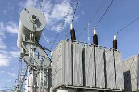
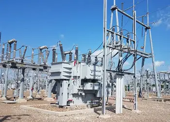
Power Transformers – Handle high voltages and operate near full load in transmission networks. They step up the voltage at generating stations and down at substations for distribution. Learn more at Electrical Power Transformers.
Distribution Transformers – Deliver safe, usable voltages to communities, buildings, and light industry. See our overview at Transformer Types.
Control Transformers – Provide stable secondary voltages for relays, PLCs, and machine tools. Details at Control Transformer.
Isolation Transformers – Decouple circuits to prevent shock hazards, eliminate ground loops, and protect sensitive equipment. More at Isolation Transformer.
Instrument Transformers – Critical for metering and protection.
Current Transformers scale high current levels for safe measurement.
Potential Transformers reduce high voltages for use in relays and meters.
Combined, they form the family of Instrument Transformers.
Dry-Type Transformers – Use air or cast resin insulation, often chosen for indoor installations and fire-safe environments. See Dry-Type Transformers.
Single-Phase Transformers – Used in residential and light commercial service, with specialized winding arrangements covered in Single-Phase Transformer Connections.
Together, these types form the industrial transformer ecosystem, each supporting the safe and efficient transfer of energy.
| Transformer Type | Primary Function | Typical Application |
|---|---|---|
| Power Transformer | Step up or step down high voltage | Transmission networks, substations |
| Distribution Transformer | Reduce voltage to usable levels | Residential, commercial, and light industrial |
| Step-Down Transformer | Convert transmission voltage to safe service | Consumer loads, small-scale distribution |
| Step-Up Transformer | Increase generator voltage | Power plants feeding the grid |
| Control Transformer | Provide stable voltage to control circuits | Machine tools, CNC, automation systems |
| Current Transformer | Scale current for measurement/protection | Relays, metering, protection systems |
| Potential Transformer | Step down voltage for measurement | Substations, monitoring instruments |
| Isolation Transformer | Electrically isolate circuits for safety | Medical devices, sensitive electronics |
| Instrument Transformer | Ensure safe, accurate metering and protection | Substations, utility monitoring |
| Dry-Type Transformer | Use air/resin cooling, fire-safe | Indoor facilities, buildings, campuses |
| Single-Phase Transformer | Operate with one primary and one secondary | Homes, small businesses, rural systems |
| Three-Phase Transformer | Deliver balanced load across three phases | Utilities, industrial power systems |
Transformers work on the principle of Faraday’s Law of Electromagnetic Induction. When alternating current flows through the primary winding, it creates a changing magnetic field in the core. This induces a voltage in the secondary winding, proportional to the turns ratio of the coil.
A step-up transformer increases voltage for efficient transmission.
A step-down transformer reduces voltage for safe local distribution.
This process happens with no moving parts, providing galvanic isolation between circuits. To explore how turns ratio affects voltage, see our guide on Step-Down Transformers.
The ability of a transformer to regulate voltage comes down to its turns ratio — the relationship between the number of windings in the primary coil versus the secondary coil. This simple but powerful principle governs whether a unit steps up the voltage for efficient transmission or steps it down for safe, usable delivery. Engineers calculate turns ratios carefully to match system requirements, maintain stable kVA ratings, and ensure energy efficiency across generation, transmission, and substation applications. By adjusting voltage without changing frequency, transformers provide electrical isolation, protect equipment, and maintain power system balance.

At the heart of every transformer is the turns ratio—the proportion of coil turns in the primary winding compared to the secondary. This ratio determines how voltage is increased or decreased between circuits.
Step-up transformers have more turns in the secondary, raising voltage for efficient long-distance transmission.
Step-down transformers have fewer turns in the secondary, which lowers the voltage for safe distribution in homes, businesses, and factories.
The long-term reliability of a transformer begins with its design. Every element — from the magnetic core to the outer bushings — must be engineered to withstand decades of electrical stress, provide stable voltage regulation, and maintain thermal performance under demanding load conditions. High-quality design reduces energy losses, extends service life, and ensures safe operation in everything from industrial control systems to utility substations. Choices in materials, insulation systems, and cooling methods directly influence efficiency, dielectric strength, and maintenance requirements.
Core: Built from laminated silicon steel or ferrite, the transformer core channels magnetic flux while minimizing eddy current losses.
Windings: Copper or aluminum transformer windings define the voltage ratio. Proper winding insulation prevents breakdown under load.
Insulation: Oil, resin, or paper-based transformer insulation provides dielectric strength and thermal stability.
Cooling: Transformer oil serves as a coolant and insulator in liquid-filled units. Dry-types rely on air or cast resin.
Components: Transformer components, such as bushings and tap changers, adapt performance to load conditions.
For a full overview of how these elements are assembled, refer to the Construction of a Transformer.
![]()
The efficiency of a transformer is one of the most important measures of its performance. Since transformers operate continuously in industrial, commercial, and substation applications, even small inefficiencies can add up to significant energy losses over time. Engineers design units to achieve high energy efficiency, maintain stable power factor, and minimize heat dissipation, but no transformer is completely loss-free. Loss reduction strategies — from better core materials to advanced insulation and cooling — directly improve operational reliability and reduce lifetime costs.
No transformer is 100% efficient. Losses occur in two main categories:
No-load losses: Core hysteresis and eddy currents.
Load losses: Resistance heating (I²R), leakage flux, and stray eddy currents in conductors.
Well-designed units can achieve efficiencies above 98%, but application and loading conditions are crucial. Explore strategies for minimizing losses in our dedicated guide on Transformer Losses.
Every transformer must be carefully matched to the system it serves, and that begins with proper ratings, sizing, and routine testing. Engineers consider the kVA rating, input and output voltage levels, frequency, and impedance to ensure each unit can safely deliver power under expected operating conditions. Ratings also determine how effectively a transformer maintains voltage regulation across varying loads, which is crucial in both utility networks and industrial control systems.
Correct transformer sizing ensures efficiency and prevents premature failure. Oversized units waste energy through unnecessary no-load losses, while undersized units risk overheating and poor reliability under sustained demand. Load calculations, cooling capacity, and fault-level analysis are all integral to the sizing process, enabling operators to balance energy efficiency with loss reduction.
Testing is the final safeguard for reliability and safety. Industry standards require a range of procedures, including dielectric strength and polarity checks, as well as turns ratio and load/no-load tests. These confirm that windings, insulation, and tap changers operate within safe tolerances. Advanced facilities may also run temperature rise and partial discharge tests to predict long-term performance. Consistent testing not only ensures compliance with international standards but also supports early detection of problems before they escalate into costly outages.
Every installation requires precise transformer specifications.
Ratings: Define input/output voltages, kVA/MVA capacity, and impedance. See Transformer Ratings.
Sizing: Engineers calculate load demand, safety margins, and cooling requirements. See Transformer Sizing.
Testing: Industry standards require dielectric, turns ratio, polarity, and load/no-load checks. More at Transformer Testing.
These factors ensure reliability, compliance, and long service life.
Advantages To Instructor-Led Training – Instructor-Led Course, Customized Training, Multiple Locations, Economical, CEU Credits, Course Discounts.
Request For QuotationWhether you would prefer Live Online or In-Person instruction, our electrical training courses can be tailored to meet your company's specific requirements and delivered to your employees in one location or at various locations.