Transformer Losses Explained
By R. W. Hurst, Editor
By R. W. Hurst, Editor
Our customized live online or in‑person group training can be delivered to your staff at your location.
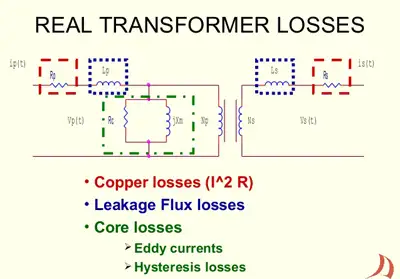
Transformer losses occur as energy dissipates through core losses, copper losses, and stray load effects. These inefficiencies impact efficiency, power quality, and system reliability in electrical networks, making loss analysis vital for performance optimization.
Electrical Transformer Maintenance Training
Substation Maintenance Training
Request a Free Training Quotation
Since distribution transformers have no rotating parts, it has no mechanical losses. This contributes to its high operating efficiency of over 90%. However, like any electrical device, it does have load losses due to several factors. These transformer losses manifest as heat, resulting in a temperature increase and a corresponding decrease in efficiency. Losses can be classified into two categories: copper losses and core dissipation. To fully understand transformer losses, it is essential to review the fundamentals of what a transformer is and how energy is transferred between its windings.
Copper Loss: This loss is caused by the resistance of the copper wire in the primary and secondary windings. A core winding can consist of hundreds of turns of fine copper wire, resulting in a relatively high resistance value. As current flows through this resistance, some power is dissipated in the form of heat. Copper losses are minimized by employing large-diameter conductors to reduce the resistance per unit length of the wires. Copper losses are generally about twice as great as core dissipation in most units.
Eddy Current Losses: Eddy currents are induced by the alternating current flowing through the core. Eddy current losses are minimized by using laminated cores. Eddy currents increase with frequency; they are directly proportional to the square of the AC voltage or current frequency. Different types of units, such as dry type transformers, experience unique patterns of copper and core dissipation depending on their insulation and cooling methods.

A rather esoteric form of transformer loss is called hysteresis loss, which occurs in all ferromagnetic transformer cores, but especially in laminated iron. Hysteresis is the tendency for a core material to act "sluggishly" in accepting a fluctuating magnetic field. Air cores essentially never exhibit this type of loss. In fact, air has the lowest overall loss of any known core material. Laminated cores exhibit high hiss loss above the AF range, so they don't work well above a few kilohertz.
At frequencies up to several tens of megahertz, powdered iron can serve as an efficient RF transformer core material. It has high magnetic permeability and concentrates the alternating magnetizing flux considerably. High-permeability cores minimize the number of turns required in the coils, thereby reducing the ohmic (resistive) loss that can occur in the wires.
At the highest radio frequencies (more than a couple of hundred megahertz), air is the preferred choice as a core material due to its low loss and low permeability.
Hysteresis losses occur in the core and result from molecular friction, which is caused by changes in the polarity of the applied current. When the magnetic field reverses, the molecular magnets also reverse their alignment and, in doing so, some power is dissipated in the form of heat.
Leakage Flux: This relatively small loss occurs due to the leakage of electromagnetic flux lines between the primary and secondary windings.
Saturation: Saturation losses may occur if the device is loaded beyond its rated capacity. This happens when the core reaches its saturation point, and an increase in current produces no additional flux lines.
An ideal transformer would have no heat depletion and would therefore be 100% efficient. Efficiency is a function of a device's copper and core depletion, and it is unrelated to the power factor. These losses are all measured in watts. The efficiency is determined the same way you calculate efficiency for other equipment. Divide the output power by the input power:
Transformers rank among the most efficient of electrical apparatus. In a standard power transformer, the full-load efficiency is generally from 96% to 99%. The core depletion is approximately constant from no-load to full-load. However, the copper losses vary with the square of the current in the winding and the winding resistance. The no-load efficiency is lower than its full-load efficiency. Therefore, sizing units to meet their expected loading greatly influences efficiency. Oversized units can contribute to inefficiency, but when they are appropriately matched to their loads, efficiency increases. Measurement devices, such as current transformers or potential transformers, are essential tools for monitoring electrical performance and quantifying efficiency losses in real-world systems.
At times, line voltages may be either higher or lower than the rated voltage of a transformer's primary. If a transformer has a voltage applied that is lower than its rated voltage, the kVA is reduced by the same percentage as the voltage is reduced. A voltage overage of one to two percent will generally be tolerated by most transformers without a reduction in magnetization. If the voltage is increased sufficiently above the rated nameplate value, the windings heat excessively, and the flux density of the core increases, causing the core saturation to exceed normal levels. Specialized units such as an isolation transformer or control transformer can reduce noise, improve voltage stability, and limit certain forms of energy dissipation.
Think you know Electrical Transformers? Take our quick, interactive quiz and test your knowledge in minutes.
Voltage regulation is a measure of how well a power transformer maintains a constant secondary voltage when given a constant primary voltage and a wide range of load currents. Voltage regulation is the difference between the no-load voltage and the full-load voltage: Whether selecting a generator step-up transformer or evaluating transformer ratings, proper specification helps reduce excess heat, avoid saturation, and optimize system reliability.
This is usually expressed as a percentage of the full-load voltage. For example, with a unit that delivers 100 volts at no-load and 95 volts at full-load, the regulation would be 5%. Voltage regulation depends on the load impedance and the total copper loss. When supplying a noninductive load, the copper loss contributes to the major portion of the voltage drop. Power and lighting transformers typically have a regulation of 2% to 4%, depending on their size and the application for which they are used. Engineers often analyze single-phase transformer connections and step-down transformers to identify how load distribution impacts copper losses.
It is important that a unit be operated on an AC circuit at the frequency for which it is designed. Transformers below 2 kVA are typically designed and rated for use at 50 or 60 Hz. When a lower frequency than the unit is designed for is used, the reactance of the primary winding decreases, resulting in a marked increase in the exciting current. This increases the flux density in the core, and without special design, higher depletion and greater heat rise will result. A 60 Hz only design is physically smaller than a 50 Hz design and should not be used on a 50 Hz circuit. Accurate transformer testing and correct transformer sizing are both vital steps in minimizing operational depletion and maintaining long-term efficiency.
If the frequency is greater than the nameplate frequency, there will be an increase in reactance and a decrease in exciting current. There will be, of course, a lower flux density, but the core loss will remain practically constant. Operating 60 Hz units at higher frequencies may simply provide less voltage regulation.
Explore 50+ live, expert-led electrical training courses –