Transformer Ratings Explained
Substation Relay Protection Training
Our customized live online or in‑person group training can be delivered to your staff at your location.
- Live Online
- 12 hours Instructor-led
- Group Training Available
Download Our OSHA 3875 Fact Sheet – Electrical PPE for Power Industry Workers
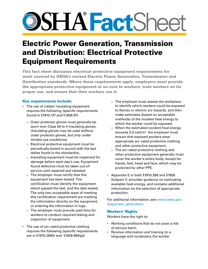
- Follow rules for rubber gloves, arc-rated PPE, and inspection procedures
- Learn employer obligations for testing, certification, and training
- Protect workers from arc flash and electrical shock injuries
Transformer ratings define the electrical limits of transformers, including kVA capacity, voltage rating, current, frequency, and cooling class. These parameters ensure safe operation, efficiency, and reliability in power distribution and industrial systems.
What are Transformer Ratings?
Transformer ratings indicate the maximum electrical limits that a unit can safely handle under standard conditions.
✅ Specifies kVA, voltage, current, and frequency limits
✅ Ensures reliability, efficiency, and thermal performance
✅ Guides selection for safe power distribution applications
Fundamental Rating Principles
Engineers rate power transformers based on the maximum output voltage and current they can deliver continuously without overheating or breakdown. This is expressed in volt-amperes (VA) or kilovolt-amperes (kVA).
For example, a unit with a 12 V output capable of supplying 10 A has a VA capacity of 12 V × 10 A = 120 VA. Due to power-supply filtering and efficiency factors, the VA rating must exceed the actual power (watts) consumed by the load.
Electrical Transformer Maintenance Training
Substation Maintenance Training
Request a Free Training Quotation
Understanding Transformer kVA and Power Levels
When selecting transformer ratings, engineers typically begin by considering the unit's size, expressed in kVA. For example, a 750 kVA unit can handle significant amounts of power in large commercial or industrial electrical systems. To correctly find a unit that matches application needs, both the load demand and the input voltage must be considered.
Transformers are manufactured for both medium voltage distribution and low-voltage service. The primary and secondary windings determine how voltage is stepped up or down, and whether the unit is configured as single-phase or three-phase affects the overall performance. Because efficiency and load variations must be taken into account, engineers typically select a unit rated slightly higher than the calculated demand.
FREE EF Electrical Training Catalog
Download our FREE Electrical Training Catalog and explore a full range of expert-led electrical training courses.

- Live online and in-person courses available
- Real-time instruction with Q&A from industry experts
- Flexible scheduling for your convenience
The term transformer kVA refers to kilovolt-amperes, a measure of apparent power. At the basic level, VA stands for volt amperes, which equals the product of volts and amps supplied by the unit. By properly matching ratings to load requirements, system designers ensure safe, efficient, and reliable operation.
Standards and Nameplate Requirements
Transformer nameplates provide the critical information engineers need to apply the equipment correctly. According to NEC Section 450.11, each unit must include:
-
Manufacturer name
-
Rated kVA
-
Primary and secondary voltages
-
Frequency (50/60 Hz)
-
Percent impedance (for units ≥25 kVA)
-
Temperature class and cooling method
-
Type of insulating fluid (if liquid-filled)
-
Required clearances for ventilation
Beyond NEC, IEEE C57, and ANSI standards govern performance and testing, while DOE efficiency regulations set minimum efficiency levels for distribution transformers in the U.S. Similar requirements exist under CSA standards in Canada.
This shows a typical transformer nameplate. Section 450.11 of the NEC outlines what information must be provided on the nameplate of each unit. Information that must be included is as follows:
Fig. 1. Typical Transformer Ratings Namplate
Losses and Efficiency
Ratings account for two categories of losses:
-
No-load (core) losses – occur whenever the unit is energized, caused by hysteresis and eddy currents in the core.
-
Load (copper) losses – caused by resistance in the windings, varying with load current.
-
Stray and dielectric losses – smaller contributions from leakage flux and insulation stress.
Efficiency curves indicate that transformers operate most efficiently at full load, where the ratio of output power to total input power is the highest. Modern high-efficiency units (meeting DOE/CSA minimum standards) exhibit lower temperature rise and reduced energy waste. Specific applications like control transformers require unique ratings that account for stability, reliability, and safe operation of control circuits.
Voltage Regulation and Impedance
Another key rating parameter is voltage regulation — the percentage change in secondary voltage from no load to full load. It depends on device impedance and power factor.
-
At lagging power factor (inductive loads), regulation is poorer.
-
At leading power factor (capacitive loads), regulation may improve or even become negative.
Formula:
% Regulation ≈ (V_no-load – V_full-load) ÷ V_full-load × 100
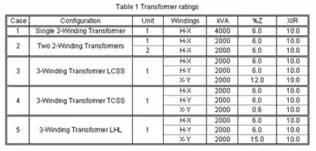
Percent impedance also appears on the nameplate. It determines fault current levels, influences short-circuit withstand capability, and affects parallel operation of multiple transformers.
Thermal Performance and Derating
Life expectancy is closely tied to temperature rise. Excessive heat accelerates insulation breakdown, leading to failure. Nameplates typically specify insulation class (e.g., 150°C, 220°C).
-
Hot-spot temperature: the hottest point inside a winding, always higher than the average.
-
Ambient temperature: usually based on 40°C; higher ambient temperatures require derating.
-
Duty cycle: Transformers designed for continuous operation must be derated if subject to intermittent overloads or nonstandard cooling.
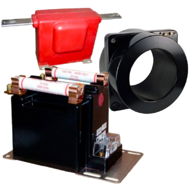
Cooling classes (ONAN, ONAF, ODAF, etc.) specify how air or oil circulation controls heat. For dry-type units, air is the primary cooling medium; for liquid-filled units, insulating oil or synthetic fluids provide heat transfer and dielectric strength. Current measurement devices, such as a current transformer, have ratings based on burden and accuracy rather than kVA capacity.
Transformer Types and Rating Variations
While distribution and power transformers share core rating principles, specialized units have additional considerations:
-
Autotransformers: share windings, higher efficiency, but reduced isolation.
-
Instrument transformers (CTs, PTs): ratings are based on accuracy class and burden, not kVA.
-
Step-up/step-down transformers: ratings must reflect transmission voltages and power levels.
-
Traction and furnace transformers: subject to high overloads and unique duty cycles, requiring special thermal ratings.
For installation in commercial or industrial buildings, dry-type transformers offer ratings that emphasize cooling, fire safety, and indoor performance.
Test Your Knowledge About Electrical Transformers!
Think you know Electrical Transformers? Take our quick, interactive quiz and test your knowledge in minutes.
- Instantly see your results and score
- Identify strengths and areas for improvement
- Challenge yourself on real-world electrical topics
Example Calculation
Suppose a 500 kVA, 13.8 kV/480 V distribution transformer has:
-
Rated current (secondary) = 500,000 ÷ 480 = 1,042 A
-
Impedance = 5% → Fault current = (1 ÷ 0.05) × full-load current = ~20,800 A
This calculation shows how ratings guide both load planning and protection system design. Ratings for instrument transformers, including current and potential transformers, are defined by precision classes and protective functions.
Table: Typical Transformer Ratings
| Rating Parameter | Common Range | Importance |
|---|---|---|
| kVA Capacity | 10 kVA – 1000 MVA | Defines the size of the load served |
| Voltage Rating | 120 V – 765 kV | Determines insulation & application |
| Frequency | 50 Hz, 60 Hz | Region-specific |
| Impedance | 2% – 10% | Affects fault current & regulation |
| Temperature Rise | 80°C – 220°C | Defines insulation life |
| Cooling Class | ONAN, ONAF, ODAF, Dry-Type | Impacts load handling |
Engineers must also consider whether a unit is designed as an isolation transformer, since ratings directly affect voltage separation and safety.
Cooling and Installation
Cooling design directly affects ratings. Methods include:
-
Air natural (dry-type) – simple, low cost, limited rating.
-
Oil natural/air forced (ONAN/ONAF) – widely used for medium/large transformers.
-
Water cooling – applied in high-capacity or restricted space situations.
The NEC requires clearances for ventilation and prohibits blocking airflow paths. Improper cooling is a significant contributor to unit failure.
Frequently Asked Questions
What happens if a unit is undersized?
It overheats, leading to insulation breakdown, reduced lifespan, and a possible fire hazard. For practical design decisions, our guide on transformer sizing explains how kVA ratings, load demand, and future expansion shape unit selection.
How do I choose the right transformer rating?
Consider load in kVA, power factor, ambient temperature, voltage regulation, and future expansion requirements. Always follow IEEE/ANSI/NEC standards.
Why is percent impedance important?
It defines fault current levels and compatibility for parallel operation.
Unit ratings provide engineers with the essential limits on voltage, current, kVA, efficiency, impedance, and thermal behavior. By considering losses, regulation, cooling, and standards, designers ensure safe, reliable, and long-lasting operation.
Related Articles


