Single Line Diagram
By R.W. Hurst, Editor
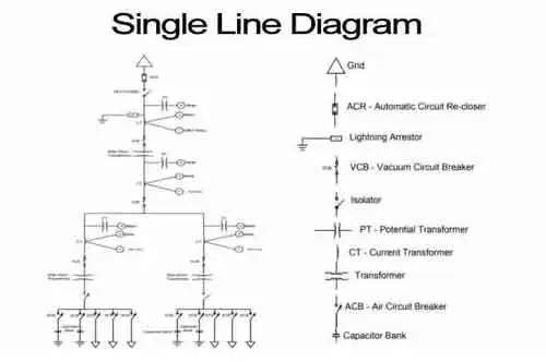
A single line diagram is a simplified representation of an electrical system using single lines and symbols to show components like transformers, circuit breakers, and busbars. It provides a clear overview of power flow and connections.
Applications of the Single-Line Diagram in Modern Power Systems
In electrical engineering, a single line diagram is a graphical representation of a circuit or system using standard electrical symbols. These schematics are used in the design, operation, and maintenance of electrical power systems. Principles such as Ampere’s Law and the Biot-Savart Law explain the magnetic effects of current flow that are fundamental to the operation of systems represented in these diagrams.
A single line diagram (SLD) is a vital tool in power engineering, providing a clear representation of how electrical components are interconnected within a system. It illustrates the flow of electricity from the power source through devices like transformers, breakers, and transfer switches, ensuring safe and efficient power distribution. Engineers rely on SLDs to analyze, design, and maintain systems by simplifying complex circuits into easy-to-read schematics. In industrial and commercial settings, these diagrams help identify critical components and streamline maintenance, making them indispensable for modern power engineering applications. Key electrical properties like capacitance and electrical resistance directly influence how energy flows through the components shown in a single line diagram.
A single line diagram is a vital tool in electrical engineering and is used extensively in the design, operation, and maintenance of electrical power systems. They provide a simplified representation of a complex system and are an efficient way to communicate the flow of electricity through the system. Electrical symbols, transformers, circuit breakers, switchgear, and protection systems are all key components of a single line, and their proper representation is crucial for the proper functioning of an electrical power system.
Key Components in a Single Line Diagram
| Component | Symbol Used | Purpose in Power Systems |
|---|---|---|
| Transformer | Two interlinked coils | Steps voltage up or down for efficient transmission and distribution. |
| Circuit Breaker | Rectangle with a line break | Protects circuits from overloads and short circuits by interrupting current flow. |
| Busbar | Straight horizontal line | Acts as a central point for electrical power distribution within switchgear. |
| Switchgear | Combination of switch icons | Houses disconnect switches and protection devices for system control. |
| Protection System | Relay or fuse symbol | Detects faults and isolates damaged sections to prevent equipment failure. |
Electrical Symbols
Electrical symbols in a single line diagram are used to represent the different components of the electrical system on a single line diagram. These symbols are standardized and used universally in the electrical industry. Some common electrical symbols that can be found include transformers, circuit breakers, switches, busbars and protection systems. Engineers frequently rely on single line diagrams when performing power system analysis, since these schematics simplify complex circuits into clear, manageable visuals.
Power System Components
A power system comprises various components, including generators, transformers, circuit breakers, switchgear, and transmission lines. These components work together to transmit and distribute electrical power. Schematics are used to represent these components in a simplified way.
Electrical distribution is the process of delivering electricity to end-users. Schematics are used to design and plan the distribution network for a specific area. The schematics help identify the components needed to provide power to the area and determine the appropriate rating of the necessary equipment.
The electricity grid is a network of power stations, transmission lines, and distribution networks that supply electricity to end-users. Schematics are used to represent the various components of the electrical grid, and to design and plan the grid. The electrical drawings are also used to monitor and maintain the grid.
Circuit breakers are safety devices that are used to protect electrical circuits from overloading or short circuits. Single lines are used to identify the location of circuit breakers in a power distribution system and to determine their ratings.
Power Transformers are electrical protective devices that are used to increase or decrease the voltage of electrical power. Single lines are used to represent transformers in a system and to determine their ratings.
Load flow analysis is the study of the flow of electrical power through a control system. Single lines are used to study a system's load flow and determine the electrical loads on each component.
Busbars are electrical conductors used to distribute electrical power. Single lines represent busbars in a system and determine their ratings.
Switchgear combines electrical disconnect switches, fuses, and circuit breakers to isolate electrical equipment, ensuring safe operation. Single lines represent switchgear in a system and determine the appropriate ratings.
Protection systems safeguard electrical equipment from damage resulting from overloading or short circuits. Single lines are used to identify a system's protection systems and determine their ratings.
Frequently Asked Questions
What is a simplified representation of an electrical power system?
A single line diagram is a simplified representation of an electrical power system or electrical grid. It illustrates the flow of electricity through the system using a single line diagram and standardized electrical symbols. The schematic is commonly used in the design, operation, and maintenance of electrical power systems.
How is a single line diagram calculated?
It is calculated using load flow analysis. This involves modelling the electrical network and calculating the current and voltage at each point in the system. Load flow analysis is a complex process requiring specialized software and electrical engineering expertise.
What is the main purpose of a single line diagram?
The main purpose is to provide a simplified overview of a power system that can be easily understood by engineers, technicians, and other professionals. The schematic helps identify potential problems in the system and enables efficient design, operation, and maintenance. Accurate diagrams clearly illustrate the movement of active power through breakers, busbars, and switchgear, demonstrating how systems are protected and controlled under various load conditions.
What are some common symbols used in a single-line diagram?
Common symbols in a single-line diagram include transformers, circuit breakers, switches, busbars, and protection systems. These symbols are standardized and used universally in the electrical industry.


Why is it important in power system planning and design?
A single line diagram is crucial in power system planning and design, as it enables engineers to identify potential issues with the system and make informed decisions about equipment sizing, protection systems, and other critical design aspects. The schematic also helps to optimize the system design and improve its efficiency.
How is it used in fault analysis and protection system design?
A single line diagram is used in fault analysis and protection system design. By modelling the electrical network and simulating various fault scenarios, engineers can then design protection systems that quickly detect and isolate faults, minimizing damage to equipment and reducing downtime.
What are the steps involved in creating a single line diagram?
The steps involved in creating a single line diagram include gathering data about the system, modelling the electrical network, selecting appropriate equipment and protection systems, and creating the schematic using specialized software. This process requires expertise in electrical engineering and a deep understanding of power systems.
How can it be used for load flow analysis and system optimization?
A single-line diagram can be used for load flow analysis and system optimization by modelling the electrical network and calculating the current and voltage at each point in the system. This information can then be used to optimize the system design and improve its efficiency.
What are some common mistakes to avoid?
Some common mistakes to avoid when creating a single line diagram include using incorrect electrical symbols, failing to label components clearly, and neglecting to consider all aspects of the system design. It is important to thoroughly understand the system and its components to create an accurate and useful single-line diagram.
Related Articles

