Load Flow Analysis - Optimizing Power
By William Conklin, Associate Editor
By William Conklin, Associate Editor
Our customized live online or in‑person group training can be delivered to your staff at your location.

Load flow analysis evaluates the flow of voltage, current, reactive power, and active power in electrical power systems. It is essential for grid planning, stability studies, contingency analysis, and efficient energy distribution under varying load conditions.
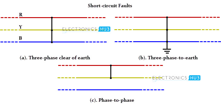
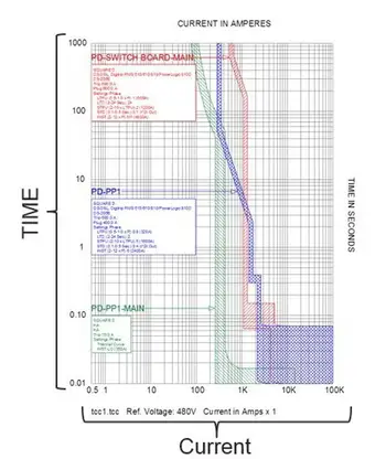
Short Circuit Analysis & Protective Device Coordination
Arc Flash Analysis/Study - IEEE 1584 Update
Load flow analysis (LFA) is a crucial aspect of electrical engineering, specifically in power system planning and operation. It is a mathematical method used to determine the steady-state operating conditions of a power system network. The process helps engineers assess voltage stability, optimize power transmission and distribution, and maintain a reliable electrical grid. A strong foundation in power system analysis and design is essential for conducting accurate LFA across modern electrical networks.
Load flow analysis, also known as load flow study, power flow study, or power flow analysis, enables engineers to create computational models of power systems to determine voltage magnitude, phase angles, real and reactive power flows, and line losses at various points within the network. This valuable information is vital in ensuring the steady-state operation of power systems and facilitating informed decision-making for power system expansion and optimization. Understanding how a phase angle calculator is critical when interpreting results from LFA, especially in large, interconnected systems.
Several methods are used to perform LFA. Two of the most common techniques are the Newton-Raphson method and the Gauss-Seidel method. The Newton-Raphson method is renowned for its rapid convergence and high accuracy, making it the preferred choice for large-scale power systems. On the other hand, although the Gauss-Seidel method is less accurate and slower to converge, it is simpler to implement and has lower computational requirements.
Think you know Electrical Engineering? Take our quick, interactive quiz and test your knowledge in minutes.
Another popular technique is the fast decoupled load flow method. This approach simplifies the power flow equations, reducing computational effort and time. It is particularly suitable for large-scale power systems where iterations can be time-consuming.
Voltage stability is a critical aspect of power system operation, and LFA plays a significant role in maintaining it. Voltage stability refers to a power system's ability to maintain acceptable voltage levels under both normal and contingency conditions. LFA helps engineers identify potential issues with voltage levels and take corrective actions, such as adjusting reactive power generation or installing additional equipment, to prevent voltage instability.
Optimizing power transmission and distribution is another crucial aspect of LFA. By evaluating the flow of real and reactive power throughout the network, engineers can identify areas with potential bottlenecks or inefficiencies. This knowledge enables them to design and implement improvements to the network, such as upgrading transmission lines, installing new generators, or optimizing the location of reactive power sources. Engineers often pair load flow analysis with short-circuit current calculation to ensure both steady-state reliability and fault protection strategies.
Several key factors need to be considered when performing LFA. These factors include the network's topology, generator locations, load slack bus assignments, and power system model types. Additionally, engineers must consider the phase angles of the power system network, power generation sources, and the generator bus P-V bus assignments.
LFA plays a crucial role in power system planning and expansion. Providing vital information on voltage levels, power flows, and line losses enables engineers to determine the optimal locations for new generation sources, transmission lines, and other equipment. This helps ensure the power system can meet growing demand while maintaining reliability and efficiency.
However, LFA faces challenges as modern electrical grids evolve. For example, the increasing integration of renewable energy sources, such as solar and wind power, introduces variability and uncertainty into the power system. This complicates LFA, as traditional techniques may need to be better suited to handle these dynamic conditions. Additionally, the growing trend toward distributed generation and microgrids introduces new complexities that require more advanced load flow analysis methods.
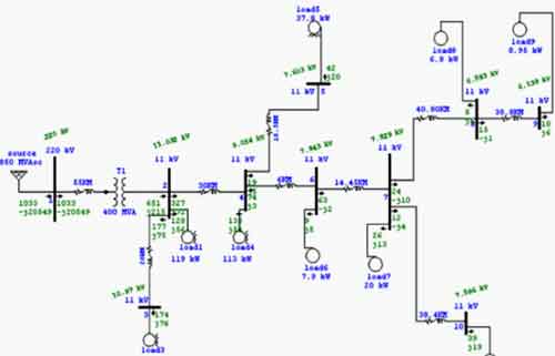
LFA is a vital tool in electrical engineering, enabling engineers to maintain voltage stability, optimize power transmission and distribution networks, and plan for future expansion. By understanding and leveraging the various techniques available for LFA, engineers can address the challenges posed by modern electrical grids and ensure reliable, efficient power delivery for all users. Visualizing system topology through a three-phase bus line diagram helps clarify how load flow analysis models different bus types and network connections.
A clear treatment of fundamentals helps readers accurately interpret results. Most studies express impedances and power in the per-unit system to normalize quantities across voltage levels. Loads may be modeled as constant power, constant current, constant impedance, or mixed ZIP models. These assumptions have a meaningful impact on voltage profiles and calculated losses.
Each bus has specific knowns and unknowns. The slack bus anchors the angle reference and balances real and reactive power to cover system losses. PV buses regulate voltage magnitude within generator reactive limits; if those limits are exceeded, the bus switches to PQ behavior. PQ buses represent aggregated loads with specified P and Q.
Download our FREE Electrical Training Catalog and explore a full range of expert-led electrical training courses.

Table: bus types and known/unknown quantities
| Bus type | Known (inputs) | Solved (outputs) | Typical role |
|---|---|---|---|
| PQ (load) | P, Q | Voltage magnitude and angle | Loads and non-regulated buses |
| PV (generator) | P, | V | (within Q limits) |
| Slack (reference) | V | and angle |
Accurate models require the network’s connectivity (radial vs meshed), transmission line and cable parameters, transformer ratings with tap settings and phase shifters, shunt compensators, and generator capability curves. Balanced three-phase assumptions are common for transmission-level studies; unbalanced models may be needed in distribution networks or where single-phase loads are significant.
The Gauss-Seidel method is simple and memory-efficient, making it suitable for small systems or teaching purposes. Newton-Raphson offers quadratic convergence and robustness on large, meshed networks, at the cost of forming and factorizing the Jacobian each iteration. Fast-decoupled load flow speeds computations by exploiting weak coupling between P–θ and Q–|V| in high-X/R transmission networks; accuracy degrades when the assumptions fail (e.g., heavy loading, low X/R, stressed voltage).
Uncertainty from variable renewables, stochastic loads, and demand response motivates the use of probabilistic load flow (PLF). Monte Carlo PLF samples input distributions to produce probability distributions of voltages, flows, and losses, enabling risk-aware planning. Other noteworthy methods include DC load flow (linear approximation for quick screening), linearized AC models for sensitivities, and the holomorphic embedding load flow method (HELM), a non-iterative approach used to assess feasibility and proximity to voltage collapse in challenging cases.
Start with data collection (single-line diagrams, equipment parameters, load forecasts), then build the network model and choose a solution method appropriate to system scale and stiffness. Run the solver, monitor convergence tolerances (e.g., power mismatches and voltage changes), enforce generator reactive limits with PV→PQ switching as required, and post-process results into actionable KPIs.
Typical outputs include bus voltage magnitudes and angles, line and transformer MVA flows, loading percentages, real and reactive losses by element and system-wide totals, as well as sensitivities to dispatch and tap changes. Engineers use these to flag undervoltage or overvoltage conditions, thermal overloads, and reactive deficiencies and to prioritize corrective measures.
Commercial and open-source tools implement similar mathematics but may differ in their default models, convergence controls, and limit enforcement. When reporting results, align with applicable IEEE/IEC/ANSI practices, and document solver settings so others can reproduce the study.
Solver robustness depends on good initial conditions, realistic parameters, and appropriate tolerances. Very tight tolerances can slow runs; overly loose ones mask violations. Ill-conditioned Y-bus matrices, poor X/R assumptions, or extreme loading can lead to slow convergence or divergence. For large systems, sparse matrix techniques and decoupled formulations improve speed and memory usage.
Load flow is a steady-state tool; it does not capture electromechanical or electromagnetic transients. Failures often trace to incorrect data, infeasible operating points, or reactive power limits, causing buses to fall out of regulation. Operators mitigate by adjusting taps, redispatching generation, adding shunt compensation, or revisiting network reinforcements.
In planning, studies support N-1 contingency screening, voltage control strategies, capacitor/reactor placement, and siting of new generation or lines. In operations, they underpin switching decisions, reactive power scheduling, and congestion management. With renewables and distributed generation, probabilistic scenarios and time-series runs help quantify variability and curtailment risk.
A small meshed system is modeled with per-unit parameters and one slack bus. After solving with the Newton-Raphson method, the results show undervoltage on two load buses and 95–100% loading on a corridor line during a generator outage. Sensitivity runs demonstrate that a modest tap increase, combined with 5–10 MVAr of shunt support, restores voltages while keeping thermal limits below 90%, guiding a cost-effective corrective plan.
Real-time and quasi-dynamic load flow integrates SCADA/PMU data for faster situational awareness. Hybrid deterministic-probabilistic workflows combine base-case accuracy with uncertainty quantification. Machine learning increasingly assists with state estimation, bad-data detection, and accelerating solver convergence, especially in very large networks. Practical applications of load flow analysis can be supported by electrical training programs that build skills in simulation, modeling, and power system operations.
Electrical Engineering Channel
Explore 50+ live, expert-led electrical training courses –