Power Factor Calculator

A power factor calculator helps you determine the efficiency of electrical power usage by measuring the ratio of real power to apparent power. Enhance energy efficiency, minimize utility costs, and accurately size electrical components with this essential tool for power systems.
What is a Power Factor Calculator?
A power factor calculator is a tool that helps evaluate the efficiency of power usage in AC circuits. It is used to optimize energy systems and correct power factor issues. It:
✅ Helps optimize power usage by calculating real vs apparent power
✅ Identifies poor power factor issues and suggests corrections
✅ Assists in improving energy savings and power quality
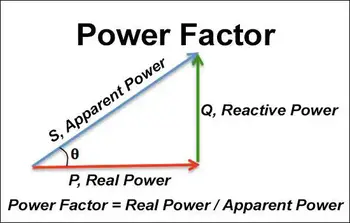
A power factor calculator typically takes as input the values of the real power and the apparent power in an ac circuit and then calculates the PF by dividing the real power by the apparent power. The resulting PF is a decimal value between 0 and 1, with higher values indicating a more efficient use of electrical power. To fully understand how power factor impacts electrical systems, refer to our guide on apparent power vs real power, which explains the underlying principles used in a power factor calculator.
Power Quality Analysis Training
Request a Free Power Quality Training Quotation
A high PF is important because it indicates that the circuit uses electrical power efficiently, which can result in lower energy costs and reduced stress on the electrical infrastructure. Therefore, it can be useful for engineers, electricians, and anyone working with electrical circuits to ensure their systems operate efficiently. If you're unsure how to compute power factor manually, our article on how power factor is calculated breaks down the process using simple formulas.
What does a power factor calculator calculate?
It is a tool that calculates the PF of an electrical circuit. PF measures how efficiently electrical power is being used in a circuit. It is the ratio of the real power (in watts) to the circuit's apparent power (in volt-amperes).
The calculator takes as input the values of the real power and the apparent power in a circuit, which can be measured using a power meter or a multimeter, and then calculates the PF by dividing the real power by the apparent power.
The real power in a circuit represents the power consumed by the electrical load, such as a motor or a heating element. The apparent power is the product of the circuit's voltage and current, representing the total power supplied to the load. The difference between the real power and the apparent PF of a circuit is called reactive power, which is the active power not directly used by the load but stored and released by reactive components.
Calculating the PF, line-to-line voltage, volt-amperes, real work, and power factors required can be determined. Apparent power and reactive power can also be calculated. Learn how reactive power influences your power factor values and how it differs from usable real power. It can provide insight into how efficiently a circuit uses electrical power and help identify opportunities to improve energy efficiency and reduce electricity costs. A high PF indicates that the circuit is using power efficiently. In contrast, a low PF indicates that the circuit is using power inefficiently and may need optimization. Learn how a power factor correction capacitor can improve system efficiency by reducing reactive power in your circuit.
Key Parameters in Power Factor Calculation
| Parameter | Symbol | Unit | Description |
|---|---|---|---|
| Real Power | P | Watts (W) | The actual power consumed by the load to perform useful work. |
| Apparent Power | S | Volt-Amperes (VA) | The total power supplied to the circuit, product of voltage and current. |
| Reactive Power | Q | Volt-Amperes Reactive (VAR) | Power stored and released by reactive components like inductors or capacitors. |
| Power Factor | PF | Ratio (0–1) | Ratio of real power to apparent power: PF = P / S. |
| Voltage | V | Volts (V) | Electrical potential difference across the circuit. |
| Current | I | Amperes (A) | Flow of electric charge in the circuit. |
| PF Correction Capacitor | C | Farads (F) | Added capacitance used to reduce reactive power and improve PF. |
Steps to calculate power factor
Here are the steps to calculate power factor.
-
Determine the real power (in watts) consumed by the load. This can be measured using a power meter or a multimeter.
-
Determine the apparent power (in volt-amperes) supplied to the load. This can be calculated by multiplying the voltage (in volts) by the circuit's current (in amperes).
-
Divide the real power by the apparent power to obtain the PF. The PF formula is Power Factor = Real Power / Apparent Power.
-
The PF will be a decimal value between 0 and 1. A PF of 1 means that the circuit is using electrical power efficiently, while a PF less than 1 indicates that the circuit is using power inefficiently due to the presence of reactive components in the circuit.
It's worth noting that PF correction can be performed to improve the PF of a circuit. This can be achieved by adding a power factor correction capacitor or by using equipment with a higher PF. A higher PF can reduce energy costs, increase system capacity, and improve voltage regulation. Learn the differences between leading vs lagging power factor and how they affect the accuracy of your power factor calculations.
Power factor correction
PF correction is the process of improving the PF of an electrical circuit by adding reactive components, typically capacitors, to the circuit. Power factor correction can be calculated using the following steps:
-
Determine the existing PF of the circuit.
-
Determine the desired PF for the circuit. A PF of 1 is ideal, but a specific target PF may be desired depending on the load and the electrical infrastructure.
-
Calculate the reactive power of the circuit. This difference between the apparent power and the real power in the circuit represents the power being stored and released by reactive components. The formula for reactive power is: Reactive power = Apparent power x sin(θ), where θ is the angle between the voltage and the current in the circuit.
-
Calculate the amount of capacitance needed for PF correction. This can be calculated using the following formula: Capacitance = (Reactive power x PF correction factor) / (2π x voltage^2), where the PF correction factor is the difference between the desired PF and the existing PF.
-
Install the appropriate capacitors to correct the PF of the circuit. The capacitance value and the installation method will depend on the specific circuit and the electrical infrastructure.
It's important to note that true PF correction should only be performed after a thorough electrical system analysis and only by qualified electricians or engineers. Incorrect PF correction can lead to over-correction and other power quality issues, resulting in equipment damage or safety hazards. Use our apparent power calculator to input your voltage and current values before determining power factor.
Poor PF refers to a situation where the PF of an electrical single-phase circuit is less than 1, indicating that the circuit needs to use electrical power efficiently. This can be due to the presence of reactive components in the circuit, such as inductive loads like motors or transformers, which cause the current to lag behind the voltage. A good automatic power factor controller can regulate efficiency in real time, improving your facility’s energy performance.
Related Articles
On-Site Training
Interested in cost effective, professional on-site electrical training?
We can present an Electrical Training Course to your electrical engineering and maintenance staff, on your premises, tailored to your specific equipment and requirements. Click on the link below to request a Free quotation.