Arc Flash Calculations To Determine Incident Energy
Arc flash calculations determine the incident energy and arc flash boundary to protect electrical workers. These calculations use system voltage, available fault current, and clearing time to define PPE requirements and safe working distances. Required by NFPA 70E and CSA Z462 standards.
Request a Free Training Quotation
What are Arc Flash Calculations?
Arc Flash Calculations are required to determine the incident energy level a worker could be exposed to in calories/cm².
✅ Determine incident energy levels and arc flash boundary distances
✅ Guide selection of personal protective equipment (PPE)
✅ Required by NFPA 70E and CSA Z462 to prevent arc-related injuries
This is outlined by NFPA 70e Electrical Safety Requirements for Employee Workplaces, which states, “A hazard analysis shall be done to protect personnel from the possibility of being injured by an arc flash. The analysis shall determine the Flash Protection Boundary and the personal protective equipment that people within the Flash Protection Boundary shall use.” In addition, IEEE Standard 1584, Guide for Performing Arc-Flash Hazard Calculations. For more details on how arc flash protection works, visit Arc Flash Protection standards.
Annex D in NFPA 70E presents the same incident energy level equations as those found in IEEE Std. 1584, but the latter goes into more detail. NFPA 70E doesn't specify that the IEEE Std. The 1584 method has to be used. The incident energy level can be determined using one of the several arc-flash software programs currently available on the market.
As understanding of the arc-flash hazard has grown, several methods for calculating the hazard have been developed. Three of these methods will be examined in this section—the theoretical model, the equations and tables used in NFPA 70E and the calculation methods presented in IEEE Std 1584. Learn more about safety standards for electrical systems and arc flash by visiting Electrical Safety Tips.
Power System Protection Courses
Short Circuit Study & Protective Device Coordination
Arc Flash Analysis/Study - IEEE 1584 Update
In addition to these two methods, other tools are available for calculating hazard levels, including various Windows and DOS-based shortcut calculator programs, IEEE 1584-based calculators on equipment manufacturers’ websites, and equipment-specific equations. Even IEEE 1584 presents two alternate calculation methods for many situations—the general equations and the simplified equations for circuit breakers and fuses. For a given system location, one can calculate several different values for incident energy levels or for the hazard boundary distance.
While the calculations may be close to one another in many situations, this may not always be the case. How can one be sure which method produces the best results for a given situation? No single calculation method applies to all situations, but several principles may be followed to ensure that the best results are obtained in a given situation:
-
Verify that actual system conditions fall within the method’s range of applicability. Many of the available calculation methods are at least partially based on empirical equations—i.e., equations derived from test results. These equations are valid within the range of system conditions for which testing was performed, but cannot be extended to other situations with a high degree of confidence. For example, the equations in IEEE 1584 cannot be used to calculate arc-flash hazard levels at locations with a bolted fault current exceeding 10^6 kA or in a DC system. This principle is also important when using the NFPA 70e tables to assess hazard levels, as the tables are based on specific assumptions regarding available fault currents and fault-clearing times.
-
Out with the old, in with the new. Hazard analysis is a relatively new field, and as a result, the available methods have undergone significant changes as our understanding of the phenomenon has grown over the past 20 years. Newer test results, industry standards, and calculation methods are more likely to accurately represent the actual hazard levels than older methods. They should be used in preference to older methods that may be based on smaller sets of test data or may be applicable over a smaller range of system conditions.
-
Use device-specific equations rather than general equations. While the general equations in IEEE 1584 are based on lab testing over a wide range of system conditions, the testing cannot possibly accurately characterize the performance of every available protective device in every possible situation.
-
Know which device clears the fault and use realistic fault current values.
First, the engineer must determine which circuit breaker is responsible for clearing the fault. Depending on exactly where the fault initiates in the panel, any of the three devices may initially act to clear the fault. Typically, the worst-case scenario involves the fault occurring on the line side of the panel’s main circuit breaker, in which case it must be cleared by the upstream feeder device (“A”).
This breaker, which would normally be set to coordinate with device “B selectively”, should have the longest tripping time of the three devices shown for a given value of fault current. Even if the arcing fault initiates on the load side of the branch circuit breaker “C”, the fault could easily propagate to the line side of the other devices in the same enclosure. Therefore, to ensure that the calculations reflect the maximum energy level to which a worker might be exposed, the trip characteristics of device “A” should be taken into account. To explore incident energy calculations in electrical safety, read our article on Incident Energy.
What value of fault current should be considered—the available bolted fault current at the switchboard containing device “A”, or the available fault current at the lighting panel itself? Suppose that a 100 kA bolted fault current is available at the switchboard, but the panel is located 100 feet away. The impedance of 100 feet of #3/0 AWG conductor drops the available bolted fault current at the panel to approximately 28 kA.
Since the concern in this case is over arcing faults at the lighting panel, the value of bolted fault current that should be used as an input to the IEEE 1584 equations is relevant. IEEE 1584 is then used to calculate the arcing fault current level, approximately 15 kA. The device’s trip characteristics must be consulted to determine its clearing time at 15 kA. Then, IEEE 1584 is used to calculate the incident energy level and protection boundary at the panel. In some situations, the best practice may be to calculate two incident energy levels and protection boundaries for a single piece of equipment. For example, consider a lineup of 480 V drawout switchgear with a main circuit breaker and several feeder circuit breakers.
The circuit breaker cubicles are more physically separated from one another than circuit breakers are in a typical electrical panel, so propagation of a fault from a feeder to the line-side of the main would be expected to be more difficult. If a fault were to occur when a feeder circuit breaker was racked in or out, then the main circuit breaker would be expected to clear the fault. However, when the main circuit breaker is racked in or out, the upstream protective device—possibly a fuse or relay on the primary side of an upstream transformer—is called upon to clear the fault.
In this case, the upstream protective device may act relatively slowly, which could mean that workers are exposed to a much higher level of hazard when racking the main than when racking a feeder. In cases such as this, or in other situations where workers may be potentially exposed to hazards in a section of gear on the lineside of the main (i.e., in a fire pump section), more than one calculation per piece of equipment may be warranted. For information on how to determine the protection boundary in arc flash situations, check out Arc Flash Protection Boundary.
Nine Steps To Performing Arc Flash Calculations
Step 1 – Identify All Locations and Equipment for Arc-flash Risk Assessment
Step 2 – Collect Data
Step 3 – Prepare a One-line Diagram of the System
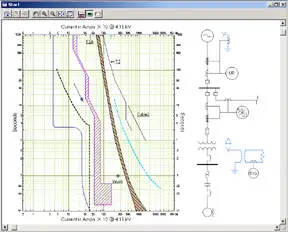
Step 4 – Perform a Short Circuit Study
Step 5 – Determine Expected Arc Current
Step 6 – Determine the Arc Time
Step 7 – Calculate Predicted Incident Energy
Step 8 – Determine the Arc-Flash Boundary
Step 9 – Document the Arc-Flash Risk Assessment
Other Arc Flash Calculation Pages
On-Site Training
Interested in cost effective, professional on-site electrical training?
We can present an Electrical Training Course to your electrical engineering and maintenance staff, on your premises, tailored to your specific equipment and requirements. Click on the link below to request a Free quotation.