


Kirchhoff's Law
By R.W. Hurst, Editor
Kirchhoff's Law, comprising the Current Law (KCL) and Voltage Law (KVL), governs electrical circuits by ensuring charge conservation and energy balance, essential for analyzing current flow, voltage drops, and network behaviour.
What is Kirchhoff's Law?
Kirchhoff's law is an essential principle in the analysis of electrical circuits, enabling a comprehensive understanding of the behaviour of complex circuits.
✅ Defines relationships between currents and voltages in electrical circuits
✅ Ensures conservation of charge (KCL) and energy (KVL) in networks
✅ Essential for analyzing and solving complex circuit problems
It consists of two fundamental rules, Kirchhoff's Current Law (KCL) and Kirchhoff's Voltage Law (KVL), which are intrinsically linked to other electricity laws, such as Ohm's law. Kirchhoff’s Law works closely with Ohm’s Law Formula to calculate voltage drops, currents, and resistance in electrical networks.
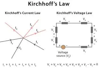
Kirchhoff's Current Law (KCL) - Also known as the first Kirchhoff's law or Kirchhoff's junction rule, KCL states that the sum of the currents entering a junction in a circuit is equal to the sum of the currents leaving the junction. Mathematically, it can be expressed as:
ΣI_in = ΣI_out
KCL is based on the principle of the conservation of charge, asserting that charge can neither be created nor destroyed. In practical terms, KCL means that, at any given point in a circuit, the total current entering must equal the total current leaving, ensuring a continuous flow of electric charge. Understanding Basic Electricity provides the foundation for applying Kirchhoff’s Current Law and Voltage Law to real-world circuit analysis.
Kirchhoff's Voltage Law (KVL) - Also known as the second Kirchhoff's law or Kirchhoff's loop rule, KVL states that the sum of the voltage gains and losses (potential differences) around any closed loop in a circuit is zero. Mathematically, it can be expressed as:
ΣV_rise = ΣV_drop
KVL is based on the principle of the conservation of energy, indicating that energy cannot be created or destroyed but can only be converted from one form to another. In electrical circuits, KVL implies that the total voltage supplied in a loop equals the total voltage drop across all components, ensuring that energy is conserved. Accurate circuit calculations require a clear grasp of Electrical Resistance and how it impacts voltage distribution across components.
Relation to Other Electricity Laws
The most significant connection between Kirchhoff's and other electricity laws is Ohm's law, which defines the relationship between voltage, current, and resistance in an electrical circuit. Ohm's law can be expressed as:
V = IR
When analyzing a circuit using Kirchhoff's laws, Ohm's law is often employed to calculate unknown quantities such as voltage drops, currents, or resistance values. By combining Kirchhoff's laws with Ohm's law, a complete understanding of the behaviour of electrical circuits can be achieved, facilitating efficient design, troubleshooting, and optimization. Applying Kirchhoff’s principles is easier when you understand key Electrical Terms used in engineering and troubleshooting.
History
Gustav Robert Kirchhoff, a German physicist, made significant contributions to understanding electrical circuits by establishing two fundamental laws: Kirchhoff's Voltage Law (KVL) and Kirchhoff's Current Law (KCL). These laws are essential tools for circuit analysis, enabling engineers to design and troubleshoot electrical networks efficiently. In addition to resistance, Capacitance plays a vital role in determining circuit behavior, especially in AC systems.
KVL, also known as the loop rule, states that the algebraic sum of all the voltages around a closed loop equals zero. This principle is derived from the conservation of energy, which ensures that no energy is lost within a closed system. In essence, KVL states that the energy supplied to a circuit is equal to the energy consumed by the components in that circuit. Therefore, when solving problems using KVL, it is essential to consider voltage drops across resistive elements like resistors and voltage rises due to sources like batteries or generators.
On the other hand, KCL, or the junction rule, states that the algebraic sum of currents entering a junction (node) in a circuit is equal to the sum of currents leaving the same junction. This law is a consequence of the conservation of charge, which posits that charge cannot be created or destroyed within an electrical circuit. KCL ensures that the total charge entering and leaving a node remains constant, with the currents (I1, I2, I3, I4, I5) balancing each other. Knowledge of Voltage Drop is essential when using KVL to assess energy losses in electrical circuits.
The significance of these laws in electrical networks lies in their versatility, as they can be applied to a wide range of circuits, from simple series and parallel circuits to more complex electrical networks. Kirchhoff's laws can be employed in conjunction with Ohm's Law, which states that the current through a conductor is proportional to the voltage across it and inversely proportional to its resistance. Using Kirchhoff's and Ohm's Law, engineers can analyze various aspects of a circuit, including voltage drops, current flow, and power distribution.
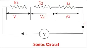
When analyzing series and parallel circuits, his laws offer valuable insight into the behaviour of electrical components. In series circuits, the current remains constant throughout the entire loop, while the voltage drops across each resistor are proportional to their respective resistances. The voltage across each branch is constant in parallel circuits, but the current is divided among the parallel resistors according to their resistances. By applying KVL and KCL to these configurations, engineers can determine the optimal arrangement of components for a given application.


To illustrate the application of his laws, consider a simple example. Imagine a circuit with a battery, two resistors in series, and a capacitor in parallel with the second resistor. By applying KVL and KCL, we can determine the voltage drop across each resistor, the current flow through each branch, and the voltage across the capacitor, enabling us to analyze the circuit's behaviour under various conditions.
Despite their usefulness, his laws have some limitations and assumptions. For instance, they assume that the components in a circuit are ideal, meaning they have no internal resistance or capacitance. Additionally, they don't account for the effects of electromagnetic fields or the finite speed of signal propagation in AC circuits. However, these limitations are often negligible in many practical applications, as they only marginally impact circuit performance. For a deeper historical context, explore the History of Electricity and the contributions of Gustav Kirchhoff to modern circuit theory.
Related Articles