Utility Transformers
How Do Transformers Work?
Download Our FREE Utility Transformers Handbook
Electrical Transformer Handbook Vol. 3
Thermal overload protection, on-line maintenance, oil-filled and gas operational applications are studied in great detail with all new articles in this 100+ page handbook on Electrical Transformers, Volume 3.
In this edition, we explore a wide range of transformer-related topics, from the selection and specification of transformers for various applications to the latest advancements in transformer design and materials. The handbook delves into the complexities of transformer operation, including load management, voltage regulation, and fault detection, with a focus on optimizing performance and reducing losses. We also provide detailed coverage of transformer testing methods, condition monitoring, and diagnostics, offering practical guidance to help professionals ensure the longevity and reliability of their equipment.
With an emphasis on modern transformer technologies, Volume 3 also covers innovations such as oil-free transformers, compact designs for renewable energy systems, and digital transformer monitoring systems that are transforming how we manage power distribution. The volume also addresses the growing importance of sustainability and energy efficiency, providing strategies for designing transformers that minimize environmental impact while maximizing operational efficiency.
Whether you are involved in the manufacturing, installation, maintenance, or operation of transformers, Electrical Transformer Handbook, Volume 3 serves as an essential resource for enhancing your knowledge and expertise in this critical area of electrical engineering. We hope this volume will empower you to navigate the complexities of transformer systems, ensuring they operate safely, efficiently, and reliably throughout their lifespan.
Latest Utility Transformers Articles
Oil in Transformers - An Insulating Medium
Is The Power Supply And The Transformer The Same Thing
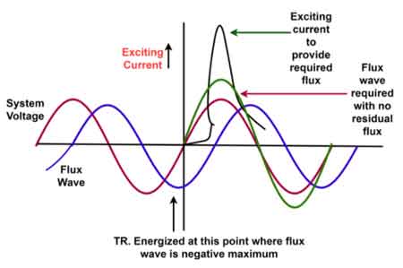
Excitation Current
Electric Pole Transformer Explained

Dielectric Fluid Performance in HV Equipment
3 Phase Pad Mounted Transformers
Utility Transformers News
Utility Transformers Media
 Bushing Monitoring: What's the Difference Between Sum of Currents and Voltage Reference
Article
Bushing Monitoring: What's the Difference Between Sum of Currents and Voltage Reference
Article
 Doble Surveys Customers, Discovers Their Most Pressing Concerns in the Workforce and Industry
Product
Doble Surveys Customers, Discovers Their Most Pressing Concerns in the Workforce and Industry
Product
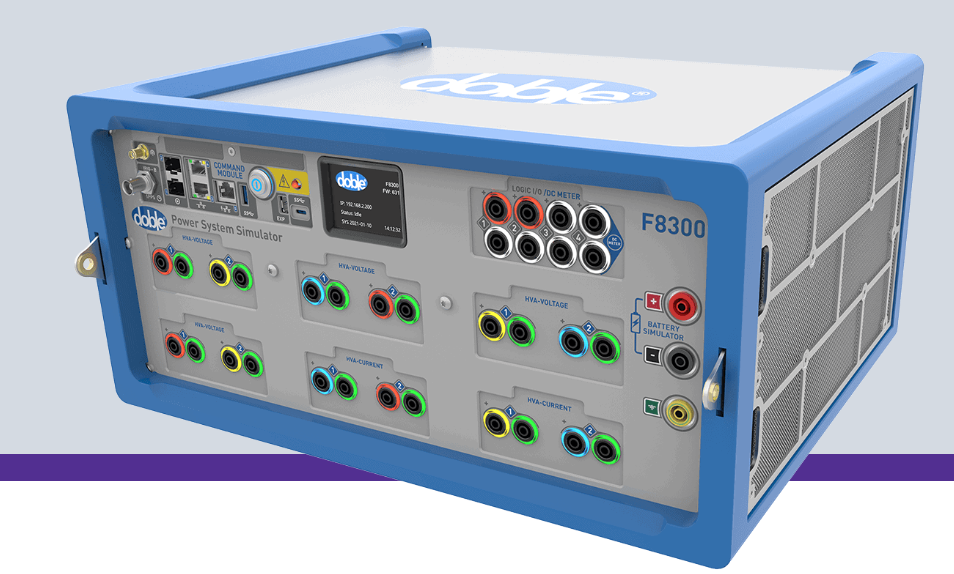 F8300 - Seven-module Test Set
Utility Transformers Articles From ET Magazine

The Role of Transformer Oil Alternatives in Improving Safety and Environmental Sustainability

Enhancing Transformer Resilience: Fire Barriers and Safety Measures in Modern Substations

Navigating the Transformer Supply Crunch: Strategies for Utilities Amidst Global Shortages

MITIGATING TRANSFORMER FAILURES: ADVANCED MONITORING AND MAINTENANCE STRATEGIES
Sign Up for Electricity Forum’s Utility Transformers Newsletter
Stay informed with our FREE Utility Transformers Newsletter — get the latest news, breakthrough technologies, and expert insights, delivered straight to your inbox.
Electricity Today T&D Magazine Subscribe for FREE

- Timely insights from industry experts
- Practical solutions T&D engineers
- Free access to every issue