High Voltage AC Transmission Lines
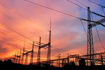
Ac transmission lines deliver alternating current across the power grid using high voltage, overhead conductors, and insulators, controlling reactive power, impedance, and corona effects to minimize losses, improve efficiency, and ensure reliable long-distance electricity transmission.
What Are AC Transmission Lines?
Ac transmission lines carry high-voltage AC power long distances with minimal losses.
✅ Typical voltages: 69 kV to 765 kV; higher reduces I2R losses
✅ Requires reactive power compensation: shunt capacitors, SVC, STATCOM
✅ Design factors: conductor bundling, corona control, insulation coordination
Three-phase electric power systems are used for high and extra-high voltage AC transmission lines (50kV and above). The pylons must therefore be designed to carry three (or multiples of three) conductors. The towers are usually steel lattices or trusses (wooden structures are used in Germany in exceptional cases) and the insulators are generally glass discs assembled in strings whose length is dependent on the line voltage and environmental conditions. One or two earth conductors (alternative term: ground conductors) for lightning protection are often added to the top of each pylon. For background on material properties, the electrical insulator overview provides relevant design considerations.
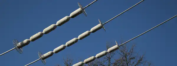
Detail of the insulators (the vertical string of discs) and conductor vibration dampers (the weights attached directly to the cables) on a 275,000 volt suspension pylon near Thornbury, South Gloucestershire, England. In some countries, pylons for high and extra-high voltage are usually designed to carry two or more electric circuits. For double circuit lines in Germany, the “Danube” towers or more rarely, the “fir tree” towers, are usually used. If a line is constructed using pylons designed to carry several circuits, it is not necessary to install all the circuits at the time of construction. Medium voltage circuits are often erected on the same pylons as 110 kV lines. Paralleling circuits of 380 kV, 220 kV and 110 kV-lines on the same pylons is common. Sometimes, especially with 110 kV-circuits, a parallel circuit carries traction lines for railway electrification. Additional context on span lengths, conductor bundles, and right of way is covered in this transmission lines reference for practitioners.
High Voltage DC Transmission Pylons
High voltage direct current (HVDC) transmission lines are either monopolar or bipolar systems. With bipolar systems a conductor arrangement with one conductor on each side of the pylon is used. For single-pole HVDC transmission with ground return, pylons with only one conductor cable can be used. In many cases, however, the pylons are designed for later conversion to a two-pole system. In these cases, conductor cables are installed on both sides of the pylon for mechanical reasons. Until the second pole is needed, it is either grounded, or joined in parallel with the pole in use. In the latter case, the line from the converter station to the earthing (grounding) electrode is built as underground cable. Engineers can review converter topologies, pole configurations, and control methods in the direct current technology guide to inform design choices.
Guidance on electrode placement, resistivity, and corrosion protection is summarized in the grounding electrodes overview relevant to HVDC return paths.
Raliway Traction Line Pylons
Pylons used for single-phase AC railway traction lines are similar in construction to pylons used for 110 kV-three phase lines. Steel tube or concrete poles are also often used for these lines. However, railway traction current systems are two-pole AC systems, so traction lines are designed for two conductors (or multiples of two, usually four, eight, or twelve). As a rule, the pylons of railway traction lines carry two electric circuits, so they have four conductors. These are usually arranged on one level, whereby each circuit occupies one half of the crossarm. For four traction circuits the arrangement of the conductors is in two-levels and for six electric circuits the arrangement of the conductors is in three levels. With limited space conditions, it is possible to arrange the conductors of one traction circuit in two levels. Running a traction power line parallel to high-voltage transmission lines for threephase AC on a separate crossarm of the same pylons is possible. If traction lines are led parallel to 380 kV-lines, the insulation must be designed for 220 kV because, in the event of a fault, dangerous overvoltages to the three-phase alternating current line can occur. Traction lines are usually equipped with one earth conductor. In Austria, on some traction circuits, two earth conductors are used. Integration with substation feeders and sectioning posts must align with the power distribution practices used along the route.
Types Of Pylons
Specific Functions:
- anchor pylons (or strainer pylons) utilize horizontal insulators and occur at the endpoints of conductors.
- pine pylon – an electricity pylon for two circuits of three-phase AC current, at which the conductors are arranged in three levels. In pine pylons, the lowest crossbar has a wider span than that in the middle and this one a larger span than that on the top.
- Twisting pylons are anchor pylons at which the conductors are “twisted” so that they exchange sides of the pylon.
- long distance anchor pylon
A long distance anchor pylon is an anchor pylon at the end of a line section with a long span. Large gaps between pylons reduces the restraints on the movement of the attached conductors. In such situations, conductors may be able to swing into contact with each during high wind, potentially creating a short circuit. Long distance anchor pylons must be very stably built due to the large weight of the exceptionally long cables. They are implemented occasionally as portal pylons. In extreme cases, long distance anchor pylons are constructed in pairs, each supporting only a single cable, in an effort to reduce the strain of large spans.
Branch Pylon: In the layout of an overhead electrical transmission system, a branch pylon denotes a pylon which is used to start a line branch. The branch pylon is responsible for holding up both the main-line and the start of the branch line, and must be structured so as to resist forces from both lines. Branch pylons frequently, but not always, have one or more cross beams transverse to the direction of travel of the line for the admission of the branching electric circuits. There are also branch pylons where the cross beams of the branching electric circuits lie in the direction of travel of the main line. Branch pylons without additional cross beams are occasionally constructed. Branch pylons are nearly always anchor pylons (as they normally must ground the forces from the branch line). Branch pylons are often constructed similarly to final pylons; however, at a branch pylon the overhead line resumes in both directions, as opposed to only one direction as with a final pylon.
Anchor Portal: An anchor portal is a support structure for overhead electrical power transmission lines in the form of a portal for the installation of the lines in a switchyard. Anchor portals are almost always steel-tube or steel-framework constructions.
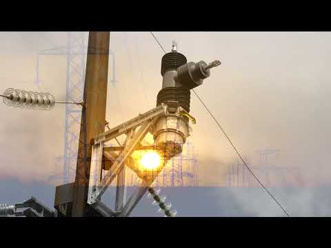
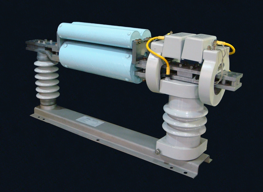
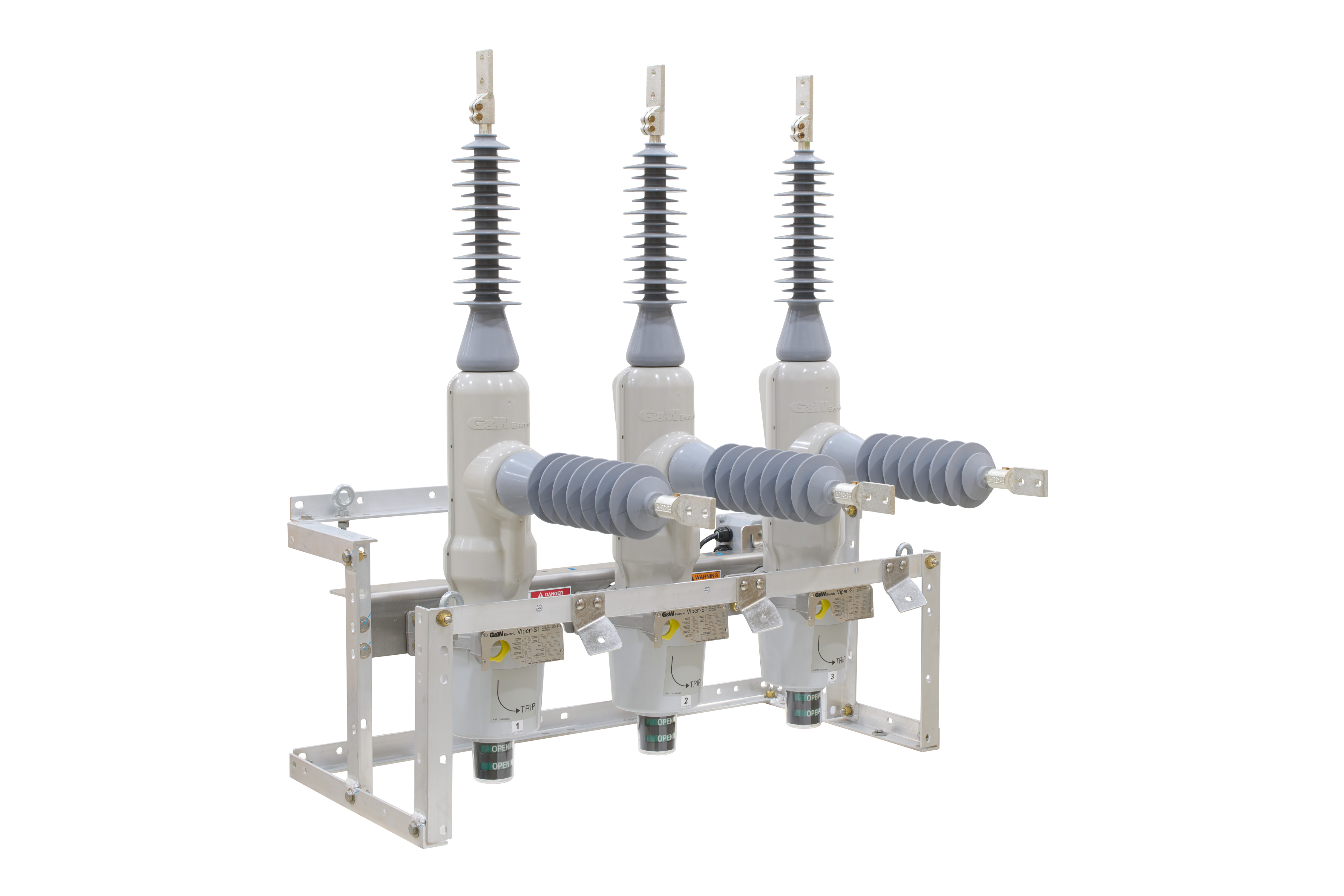
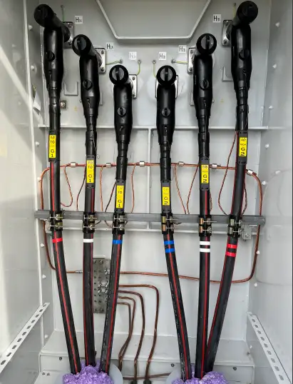
Termination Pylon: Anchor pylons or strainer pylons utilize horizontal insulators and occur at the endpoints of conductors. Such endpoints are necessary when interfacing with other modes of power transmission (see image) and, due to the inflexibility of the conductors, when significantly altering the direction of the pylon chain. Anchor pylons are also employed at branch points as branch pylons and must occur at a maximum interval of 5 km, due to technical limitations on conductor length. Conductors are connected at such pylons by a short conductor cable “strained” between both ends. They often require anchor cables to compensate for the asymmetric attachment of the conductors. Therefore, anchor pylons tend to be more stably built than a support pylon and are often used, particularly in older construction, when the power line must cross a large gap, such as a railway line, river, or valley. A special kind of an anchor pylon is a termination pylon. It is used for the transition of an overhead powerline to an underground cable. A termination pylon at which the powerline runs further as well as overhead line and as underground cable is a branch pylon for a cable branch. For voltages below 30kV, pylon transformers are also used. Twisted pylons are anchor pylons at which the conductors are “twisted” so that they exchange sides of the pylon. Anchor pylons may also have a circuit breaker attached to their crossbeam. These so called switch pylons are operated from the ground by the use of long sticks. The attachment of circuit breakers to pylons is only practical when voltages are less than 50kV. Where sectionalizing or protection is required aloft, utilities are adopting overhead switchgear innovations to reduce footprint and maintenance.
Materials Used
- Wood Pylon
- Concrete Pylon
- Steel Tube Pylon
- Lattice Steel Pylon
Conductor Arrangements
Portal Pylon: In electricity distribution, a portal pylon is a type of pylon with which the cross beams on the conductor cables rest on at least two towers. Portal pylons can be made of wood, concrete, steel tubing or steel lattice. They are used in German railroad wiring because of their enormous space requirement as a rule only for anchor pylons, which have to resist high traction power and as bases for lines in switchgears as anchor portals. Their application and clearances are coordinated with prevailing electrical distribution systems standards for safe operation.
Delta Pylon: A delta pylon is a type of support structure for high-voltage electric power transmission lines. The pylon has a V-shapedtop for the admission of the cross beam. Delta pylons are usually established only for one electric circuit, occasionally for two electric circuits. They are used for voltages up to 765 kV. Delta pylons are far more common in the USA, France, Spain, Italy and formerYugoslavia, while in Germany on delta pylons shifted high voltage transmission lines are very rare.
Single-level Pylon: A single-level pylon is an electricity pylon for an arrangement of all conductor cables on a pylon in one level. The singlelevel pylon leads to a low height of the pylons, connected with the requirement for a large right of way. It is nearly always used for overhead lines for high-voltage direct current transmissions and traction current lines. If three-phase current is used, if the height of pylons may not exceed a certain value.
Two-level Pylon: A two-level pylon is a pylon at which the circuits are arranged in two levels on two crossbars. Two-level pylons are usually designed to carry four conductors on the lowest crossbar and two conductors at the upper crossbar, but there are also other variants, e.g. carrying six conductors in each level or two conductors on the lowest and four on the upper crossbar. Two-level pylons are commonplace in former West-Germany, and are also called Donau pylons after the river Danube.
Three-level Pylon: A three-level pylon is a pylon designed to arrange conductor cables on three crossbars in three levels. For two three-phase circuits (6 conductor cables), it is usual to use fir tree pylons and barrel pylons. Three-level pylons are taller than other pylon types, but require only a small right-of-way. They are very popular in a number of countries.
Three-level Pylon: A three-level pylon is a pylon designed to arrange conductor cables on three crossbars in three levels. For two three-phase circuits (6 conductor cables), it is usual to use fir tree pylons and barrel pylons. Three-level pylons are taller than other pylon types, but require only a small right-of-way. They are very popular in a number of countries.
From: Overhead and Underground T&D Handbook, Volume 1, The Electricity Forum
Related Articles
On-Site Training
Interested in cost effective, professional on-site electrical training?
We can present an Electrical Training Course to your electrical engineering and maintenance staff, on your premises, tailored to your specific equipment and requirements. Click on the link below to request a Free quotation.