RTU and HMI Redundancy in Electrical Substations
As the substation RTU takes on more applications, such as Human-Machine-Interface (HMI), alarm annunciation, math & logic and “relay communication processing”, its need for high availability increases. Anything that takes the RTU out of service – configuration change, firmware update, or component failure – means not only loss of SCADA but also loss of local visibility, loss of non-operational data and, in some applications, loss of local control. Redundancy can address the needs for higher availability. This paper reviews the latest designs for electrical substation RTU redundancy and details required new features, including:
• Current redundancy designs in substation automation
• Limitations of current implementations
• Suggested design philosophies for substation automation redundancy
• Review of desirable redundancy design features:
o Flexible SCADA interface, including intelligent buffering to prevent Event floods on switchover, selective reporting of Events and acceptance of controls by Standby, and multiple SCADA support
o Ability for the SCADA Master to make a connection to a single IP address shared by both RTUs
o Robust and secure communication link between Active RTU and Standby RTU
o Ability to bi-directionally replicate operator actions on the local HMI such as tagging, alarm acknowledgement and blocking/forcing of point states (to ensure uninterrupted visibility after failure and throwover)
o Ability for both Active RTU and Standby RTU to access SCADA data from IEDs.
o Ability to compare data from Active and Standby RTUs
o Ability to block Standby polling
o Ability to obtain diagnostic data from Standby RTU to confirm health
o Ability to manually force throwover
o Ability for users to select criteria for throwover, and to force auto-throwover
o Ability to test configurations on Standby RTU while Active operates normally
o Auto-transfer of configuration files from Active RTU to Standby RTU
o Design that keeps Active and Standby databases synchronized
o Graphic user interface to indicate redundancy status and health
Definitions
RTU 1 and RTU 2 The redundant pair of RTUs
Active RTU The RTU that is performing the application tasks
Standby RTU The RTU that is ready to take over
Throwover The actions, automatic or forced, that make the Standby RTU Active
Research and Sources
The material in this paper was primarily obtained through direct interviews with engineers and managers at the following utilities: ConEd (NY, USA), Eversource (CT, USA), Entergy (MS, USA), PPL Utilities (PA, USA), BPA (OR, USA), Xcel (MN, USA) and Dairyland Coop (WI, USA)
Other material for this paper was obtained from public web sources for the leading world suppliers of RTUs and substation automation, and from NovaTech internal sources.
Current Redundancy Designs in Substation Automation
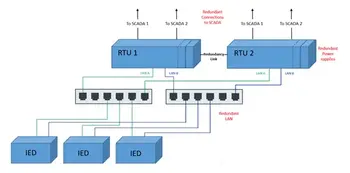
For the substation RTU, designs currently exist for most of the hardware and network redundancy. Figure 1 below shows a modern architecture with redundant SCADA connections, dual RTU power supplies and redundant LANs; Parallel Redundancy Protocol (PRP) in this example.
Figure 1: Modern RTU design with redundant SCADA connections, redundant LANs and dual power supplies
In the most recent redundant RTU designs, powers supplies – arguably the hardware component most likely to fail - are “hot-swappable” from the front. Redundant SCADA connections are supported and some systems will flip-flop Ethernet and protocol addresses, and intelligently clear buffers on the Standby RTU. High-speed standards-based redundant broadband LANs can replace proprietary networks; Parallel Redundancy Protocol (PRP) and High-Availability Seamless Ring (HSR) are gaining favor over other standards as they are sufficiently fast and deterministic for protection applications with 61850 GOOSE. Many modern IEDs are also able to manage independent buffers on multiple sockets on the same physical port, important when both RTUs needs to poll all IEDs for Events. See Figure 2 below:
Figure 2: IED supporting multiple sockets with independent event buffers on one physical port
Current implementations improve uptime by eliminating single points of failure, and by enabling failures to be diagnosed and repaired while maintaining operation.
Limitations of Current Implementations
Looking at the current RTU redundancy state-of-the-art, one may ask why so few redundant RTUs are seen in substations, notably in the US. Reasons include:
1) RTUs in the larger and more critical substations – where redundancy is most often considered – are now taking on non-traditional RTU tasks such as Human-Machine-Interface (HMI), alarm annunciation, math & logic processing and “relay communication processing” (passthrough relay access), Each of these tasks imposes specific and complicating requirements on the redundancy design, such as bi-directionally replicating user-initiated actions from one HMI to another, or enabling predictable hand-off of control on switchover.
2) Interface to legacy SCADA requires more flexibility in the redundancy design, notably where multiple SCADA connections from different organizations are required. Each may have different needs; one serial, one broadband. One may want Events from both RTUs; the other may not. One may want certain controls issued from both RTUs, others will not. Etc.
3) Not all IEDs are able to accommodate connection to both RTUs, and a substation may have some IEDs than can and some that can’t. Accommodating mixed vintage IEDs becomes a redundancy design and operational challenge.
4) Living with complicated redundant RTUs can be challenging, and the hand-off from engineering to operations may never be quite complete. Few designs provide clear diagnostics and status data, intuitive throwover controls, simple methods to keep programs in sync, or simple methods to test new configuration before going online.
Suggested Design Philosophies for Substation Automation Redundancy
An important step in designing improved substation RTU and HMI redundancy is to define design philosophies. Suggestions:
1) The system design will continue to meet user performance requirements* with the failure of any one system component.
2) The failure of one portion of the system should not cause a failure in another portion of the system.
3) Any failure should be automatically detected, specifically identified, and annunciated.
4) Any failure should be able to be fixed without rendering the system inoperable.
5) Changes should be able to be made to the system while continuing to meet user systems performance requirements*.
6) A technician-level employee should be able to operate, maintain and repair the system.
*presenting data to SCADA, solving logic, refreshing HMI screens with fresh data, logging alarms and SOE, etc
Review of Desirable Design Features
o Flexible SCADA interface, including intelligent buffering to prevent Event floods on switchover, selective reporting of Events and acceptance of controls by Standby, and multiple SCADA support.
Basic clearing of event buffers when Standby to prevent event flood on switchover is straightforward, but increased complexity is introduced when the Standby RTU is also required to respond to event polls, or to accept controls. See scenarios in Figure 3 below.
Figure 3: Standby RTU responses to SCADA, with or without Events and controls
Further complication is added when multiple SCADA Masters impose varying requirements. See Figure 4 below.
Figure 4: Standby RTU response to multiple SCADA Masters, each with or without Events and controls
o Ability for the SCADA Master to make a connection to a single IP address shared by both RTUs
Needed here is a standards-based approach. Low-level custom coding in the RTU can force the Ethernet address to the one that SCADA polls, but custom approaches may not gracefully make and release connections, may not make other fixed addresses available and may not be easy to maintain. A standard such as Common Address Redundancy Protocol (CARP) may serve well here (pending how this may affect cyber security) where the RTU that is “Active” takes on a virtual common address, and a fixed address remains for user interface. See Figure 5 below.
Figure 5: Ethernet address management with Common Address Redundancy Protocol (CARP)
o Robust and secure communication link between Active RTU and Standby RTU
The link between the two RTUs should be redundant and monitored in order to eliminate a single point of failure. The link should also offer an encryption option to enable the two RTUs (or SCADA Masters) to be placed in geographically separate locations.
o Ability to bi-directionally replicate operator actions on the local HMI such as tagging, alarm acknowledgement and blocking/forcing of point states
The substation HMI integral to the RTU typically will include alarming, tagging, and “blocking” functions for maintenance. For safety reasons, operator actions on the one RTU should be replicated on the other RTU to ensure consistent awareness. When an alarm is acknowledged by an operator on the Active RTU, it should appear as acknowledged on the Standby RTU. Similarly, when a tag is placed or removed on a controllable element on the Active HMI, it should appear, or disappear from the HMI on the Standby RTU. These real-time operator actions must be retained through power cycles, and preferably, should be bi-directional; e.g. tags placed on the Standby RTU HMI should appear on the Active RTU HMI.
o Ability for both Active RTU and Standby RTU to access SCADA data from attached IEDs
It is important, where possible, to have both the Active RTU and the Standby RTU poll data from IEDs, or accept data reports from IEDs. This enables operators to confirm network health to the Standby RTU before throwover occurs.
o Ability to compare data from Active and Standby RTUs
When both RTUs poll the same sets of data from IEDs, or when data is reported to both RTUs from IEDs, data comparison, and dual data reporting should be possible. Comparison of data accessed by Active and Standby RTU may be useful to confirm proper scaling and time synchronization in IEDs and RTUs. When a critical piece of data is used in control algorithms, confirming it as the same from Active RTU and Standby RTU increases assurance of proper control.
o Ability to block Standby polling
In some applications with polled architecture, and with mixed version IEDs, not all IEDs may be able to accept connections from both RTUs at the same time. In other applications, such as where the RTU is performing an extended role as a small SCADA Master, polling of the substation RTUs by the Standby SCADA system may be impractical or impossible. In both these cases, selective blocking of the polling by the Standby is important.
Figure 6: RTU in extended role as a small SCADA Master. The “Block Polling” feature may be important in this application.
o Ability to obtain diagnostic data from Standby RTU to confirm health prior to throwover
The health and status data from the Standby RTU should be accessible, including temperature, power supply status, time sync accuracy and comm integrity. Security status should also be accessible: names of users attached, how they are attached, syslog data, etc. Access of these data enables users to address problems prior to throwover, and to respond to security events quickly.
o Ability to manually force throwover
Situations will occur during operation and maintenance where it will be necessary to force the Active RTU into Standby (which will make the Standby RTU go Active). Examples: when the Standby RTU is healthier than the Active RTU, and where hardware in the Active RTU must be upgraded.
o Ability for users to select criteria for throwover, and to force auto-throwover
Situations will occur where the Standby RTU is healthier than the Active RTU. Examples:
-One power supply failed in the Active RTU, both healthy in the Standby;
-Active RTU lost time sync. Standby RTU synced up fine;
-Points from IEDs coming in offline at Active RTU, but online at Standby.
-SCADA polling the Standby fine, but not polling the Active
The user may want to select these criteria and conditions to force auto-throwover.
o Ability to test configurations on Standby RTU while Active operates normally
The Standby RTU should be able to be forced into a special mode where it is functionally isolated from the redundancy application. In this mode, configurations should be able to be tested safely without any impact on the Active RTU. This mode is also useful for firmware upgrades.
o Auto-transfer of configuration files from Active RTU to Standby RTU
Complicated RTUs with integral HMI may include multiple configuration files for logic, graphics pages and RTU point mapping. In redundancy designs that require configurations to be identical, an automatic mechanism to move configuration files from Active RTU to Standby RTU reduces setup steps and reduces errors.
o Design that keeps Active and Standby databases synchronized
Keeping Events from being double-reported, or lost on throwover, is minimized when the Active RTU database is replicated to the Standby RTU. Real-time control algorithms are also able to be executed more reliably on throwover when databases are synchronized.
o Graphic user interface to indicate redundancy status and health
Text-based diagnostic, status and control screens work fine, but some users prefer a more intuitive and simple graphic to indicate redundancy system health, including which RTU is which, connection status, health and controls. Design concept in Figure 7 below.
Figure 7: Design concept for redundancy diagnostics, status and control
Conclusion
As the substation RTU takes on new tasks, redundancy and the higher availability it brings will increase in importance. Although current redundancy solutions are sufficient for the basic substation RTU function, RTUs that serve broader roles in the substation will require new features, expanded flexibility and simplified operation.
On-Site Training
Interested in cost effective, professional on-site electrical training?
We can present an Electrical Training Course to your electrical engineering and maintenance staff, on your premises, tailored to your specific equipment and requirements. Click on the link below to request a Free quotation.