3D Substation Design Explained
Since Thomas Edison designed his Pearl Street Station in 1882, engineers have had to contend with presenting their design on paper—the very essence of 2D space. Edison’s answer to the need for a 3D presentation was to prepare an artistic rendition of the space.
Electrical Transformer Maintenance Training
Substation Maintenance Training
Request a Free Training Quotation
Today, we have one advantage that Edison lacked—the computer. Engineers are now free to let their visions soar and investigate options that make facilities more economical, dependable, and safer to operate. This can be achieved utilizing the power of 3D design. But to do this, a Toolbox of building blocks and software is required. It can be a very time-consuming task to develop such a Toolbox.
Figure 1. Artist rendition of Edison’s Pearl Street Station (Copyright unknown)
History of AutoCAD 3D
The use of Computer Aided Design (CAD) in the preparation of substation design drawings goes back to the 70s and 80s. These early systems generally utilized main-frame computers and dedicated workstations putting the cost out of reach for the average Utility system. Autodesk®, then based in Mill Valley, CA, released PC-based 2D AutoCAD 1.0. Support of 3D, even rudimentary, would not arrive until 1985. The following chronicles AutoCAD’s development of 3D.
-
1985 – Version 2.1 introduced 3D Level 1 which included 3D wireframe visualization.
-
1987 – Version 2.6 added 3D Level 2 with 3D Line, 3D Face and 3D Plot capabilities.
-
1994 – Release 13 included 3D solid modelling functions based on the ACIS 3D kernel.
-
2007 – Release of AutoCAD 2007 in 2006 introduced the SectionPlane command which allowed for the generation of section objects acting as cutting planes through 3D objects.
-
2009 – AutoCAD 2010 introduced the SectionPlaneToBlock command which saves selected section planes as 2D or 3D blocks or as drawings.
With AutoCAD, all of the necessary drawing tools were available to produce 3D Substation Design efficiently.
In 1999, Autodesk released Inventor® (a non-AutoCAD product), their flagship application for “professional-grade 3D mechanical design, documentation, and product simulation tools”. It has been used extensively for 3D substation design. However, with the annual prescription rate for Inventor around $2,000 per year per user, it is not economically feasible for many smaller utilities. Alternately, many smaller utilities do currently utilize AutoCAD for Work Order production and/or mapping. And, with the right tools, it has all of the features necessary to be an economical and efficient method of producing quality 3D design drawings.
Substation Design
A complete substation design project typically consists of three major tasks as follows:
-
Structure design – This involves the physical layout of all structures and appurtenances. It consists of a Plan View and a number of Section Views (or Elevations) that convey the layout of the substation to the substation material packager. From this all of the material required to construct the substation can be determined. This represents 30%-60% of the design time.
-
Relaying and Control design – This includes relays, housing, wiring and conduits required to interconnect the various equipment. This requires physical drawings as well as circuit, schematic and wiring diagrams.
-
Specifications and contract documents are required to procure the material and employ a contractor to construct the substation.
Substation design is commonly accomplished using one of two methods. The design can be achieved using staff personnel, or a design consultant can be retained. In many instances, a consultant is retained because either the Utility’s staff does not have the expertise or, more often, they do not have the time. The consultant fee for preparing a complete substation design for even a modest substation can easily range from $75,000 to $200,000.
While a Utility may not have the personnel to accomplish all of the design tasks, it is possible to undertake the Structure design and cut the total consultant fee by 30%- 60% or more. The key to this is to efficiently create the physical structure layout. This is where 3D design is a major advantage.
Figure 2. Plan View with Section Lines
2D vs 3D
In substation design, several major steps must be taken to develop the Plan and Section (Elevation) drawings. These are detailed in Table 1.
Figure 3 –Typical Elevation View with Dimensions, Bus Labels and Bubbles
In 2D design, if any modifications are made to the Plan View, one or more of the Elevations must be checked and possibly modified. Likewise, changes to the Elevations may result in modifications to the Plan View. In all cases, conflicts must again be reviewed and resolved. The BOM will need to be reviewed and possibly updated.
However, changes made to the 3D Plan View can easily be reflected in the Elevation views using AutoCAD by modifying the Sections and regenerating the elevations with the SectionPlanetoBlock command. If necessary, the BOM can be easily regenerated.
Benefits of 3D over 2D Design
There are several benefits to utilizing a 3D approach to design.
The design cycle is reduced. This is crucial to the justification of utilizing staff personnel for this task. The substation design is prepared completely in the Plan View utilizing a Toolbox of 3D parts and software applications. All Elevation views are then generated from the Plan View. Changes to the design on the Plan level are easily reflected in the Elevations with minimal time expended. The results are fewer design errors encountered during construction.
- Construction costs are reduced. The more accurate design inherent in the 3D process results in fewer conflicts, fewer errors during construction and fewer Change Orders in the construction phase. Additionally, by presenting a perspective view, the contractor can more easily interpret the drawings.
- The reduced design cycle and construction cost savings reduce the total project cycle cost and the overall project cost.
- Operational safety is increased. 3D design allows the engineer to check for adequate clearances as the design progresses, not only for buses and structures but also for the operation of equipment such as switches and fuses.
Figure 4. 3D Substation perspective view
One major drawback to 3D drawings is that the development of 3D blocks and their manipulation in 3D space can be very tedious.
When initially delving into 3D design, the first problem that becomes evident is the need for 3D blocks that accurately represent the various pieces and parts that go into the substation. This requires researching the numerous manufacturers of the many parts involved and the best manner to present them.
Once this is overcome and the structures and equipment are placed in the drawing, the electrical interconnections must be made. This requires the placement of buses and jumpers that not only do not lie in the same physical plane but often lie in planes that are skewed from each other. At this point, the engineer may reconsider the decision to design in 3D.
The solution is a third-party system that can provide pre-defined substation blocks and applications that greatly simplify the total process. One such system is the 3DToolbox offered by 3DUtility.
The 3DToolbox
The 3DToolbox consists of 3D AutoCAD blocks (referred to as Units) and software applications that empower the Design Engineer to create Structure design drawings suitable for procuring material and contractors. The applications are built on AutoLisp, an intrinsic AutoCAD programming language and Microsoft® Visual Basic for Applications (VBA) for AutoCAD. Autodesk distributes VBA for free and is easily integrated with AutoCAD for all supported releases.
The 3DToolbox utilizes Microsoft® Excel for reporting the Bill of Materials. However, output to a CSV file format is also supported. No other software application is required for its operation.
The 3DToolbox contains over 600 3D Units in the following folders:
-
Condulets – Used for control conduits and low-voltage circuits.
-
Connectors – Bus supports, couplers, stud connectors, tees and terminals for tube and conductor bus.
-
Equipment - Lightning Arrestors, Bushings, CTs, VTs, Lighting, etc.
-
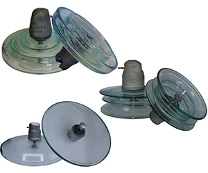
Insulators - Standard TR as well as High Strength, Extra High Strength and polymer, 15kV through 230k.
-
Major Equipment - Breakers, Circuit Switchers, Power Transformers and Switchgear Houses, 15kV thru 161kV.
-
Structures - Switch and Bus supports, Breaker and Terminal structures.
-
Transmission – Transmission pole line hardware, including fittings, insulators, conductor clamps, etc.
-
Distribution – Distribution pole line hardware including fittings, insulators, crossarms, conductor deadends, etc.
Figure 5. Connector Units
In addition to individual Units, Units can be nested within other Units and blocks to form Assemblies. Assemblies can be placed in a single operation, saving the Engineer considerable time dealing with minute details. The following are examples of Assemblies:
- Breaker Assembly – contains Structures, Insulators, Connectors, Busses and Jumpers, Switches and Breakers.
- Metering Assembly – contains Structures, Insulators, Connectors, CTs, VTs, Meter Cabinet with Condulets and conduit.
- Switch Structure Assembly –a Structure complete with Switches, switch operator and grounding pad.
- Using the 3DToolbox Units, the system is easily extensible by creating additional Assemblies specific to each Utility, which can be customized easily from the 3DToolbox as required.
Figure 6. Units & Assemblies insert form
In addition to the Units and Assemblies, several software applications are provided to simplify the drawing preparation process, including:
-
Unit Insert Form – Provides a simplified method for inserting Units into the drawing and manipulating their orientation. This is a VBA app.
-
Jumpers—Six routines are provided that cover all jumper connection configurations, including connector-to-connector, multiple connectors, connections between buses, and between buses and equipment. These apps simplify one of the most complex tasks since the manipulation of jumpers in 3D space, often not linear in nature, can be quite time-consuming. These are AutoLisp apps.
-
Bus creation—One of 3D's advantages is its visual aspect. Bus creation tools, which are AutoLisp apps, simplify the production of pipe, angle, flat, and conductor buses.
-
Section & Elevation creation – Simplifies the AutoCAD Section and SectionPlaneToBlock commands.
-
Bill of Material (BOM) – A major advantage of 3D is that the Plan drawing includes all of the parts and pieces necessary to construct the substation. This provides an accurate count of all of the Connectors, Equipment, Switches, Busses, etc. required to construct the substation. This is a very powerful tool to assure that the substation packager’s list of provided material is accurate thus alleviating delays due to material delivery. This is a VBA app.
-
Miscellaneous applications for manipulating blocks, designing checks and displaying drawings.
Design of substations in 3D has been available for many years. However, the cost associated with the specialized software and training has left it out of reach of many smaller utilities. With the advent of systems such as the 3DToolbox, any utility that currently uses AutoCAD or any of the AutoCAD-compatible programs (such as BricsCAD®) can enter the 3D arena with little cost. And the potential savings are considerable.
George Flew, PE, developed the 3DToolbox. He entered the CAD substation design field in 1982 with Release 1.2 of AutoCAD when he presented it to his employer, Allen & Hoshall, Inc. He spent his career designing substations, transmission and distribution systems, and system planning in the Public Utility sector. Since retiring in 2017 as the VP of Engineering for Jackson Energy Authority, Jackson, TN, he has devoted over a man-yearto developing the 3DToobox. After 43 years of memorable and dedicated work in the Public Utility field, he has released the entire 3DToolbox free of charge to any public utility entity.
On-Site Training
Interested in cost effective, professional on-site electrical training?
We can present an Electrical Training Course to your electrical engineering and maintenance staff, on your premises, tailored to your specific equipment and requirements. Click on the link below to request a Free quotation.