


Advancements in Dissolved Gas Analysis: CO/CO2 Ratio
By Dr. Zachary H Draper & Dr. James J Dukarm
Download Our NFPA 70E Fact Sheet – 2024 Electrical Safety Edition
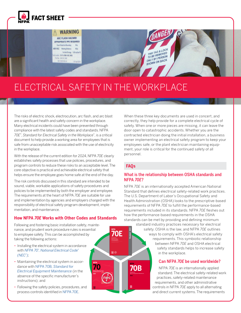
- Understand how NFPA 70E works with NEC and NFPA 70B standards
- Clarify the shared responsibility between employers and employees
- Learn how NFPA 70E supports OSHA compliance
Advancements in Dissolved Gas Analysis CO CO2 Ratio optimize transformer diagnostics with machine learning, IEC 60599 interpretation, insulation aging assessment, fault detection, and predictive maintenance for condition monitoring of power transformers.
What Are Advancements in Dissolved Gas Analysis CO/CO2 Ratio for Transformer Diagnostics?
New methods refine CO/CO2 ratio interpretation using ML, online sensors, and IEC 60599 to assess paper aging.
✅ CO/CO2 thresholds aligned with IEC 60599 and IEEE C57.104
✅ Online DGA sensors and digital twins for real-time aging insights
✅ Machine learning models correlate ratios with DP and hot-spot temp
For DGA interpretation, faults identified using hydrocarbon gases are considered more serious if they appear to affect paper insulation. That is made explicit in CIGRE technical brochure 771 [1]. Production of hydrocarbon gases from the oil by electrical or thermal stress does not significantly affect the oil’s function as a coolant or electrical insulator. On the other hand, production of carbon oxide gases from paper insulation raises a concern of paper deterioration. In particular, charring of the paper by a localized hot spot, especially in the windings, can lead to transformer failure.
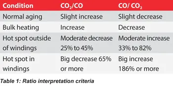
Recently R. Cox and C. Rutledge have developed a method for judging the location of a fault in paper insulation from the percent change of the CO2/CO carbon oxide gas ratio [2, 3]. In a controlled experiment with a sacrificial transformer and a heating element, they found that direct heating of paper tends to generate more CO than CO2. Case studies of faulty transformers have revealed that a large percent decrease in CO2/CO is associated with charring of winding paper. A moderate percent decrease in the ratio is often associated with paper charring outside of the windings, such as on bushing or tap changer leads. A minor percent decrease or an increase of the ratio (with production of carbon oxide gas) is usually associated with mild bulk overheating of paper insulation rather than a localized hot spot. See Table 1 for details. For readers new to the topic, an overview of dissolved gas analysis principles can clarify how gas ratios inform fault localization.
Test Your Knowledge About Dielectric Fluids!
Think you know Dielectric Fluids? Take our quick, interactive quiz and test your knowledge in minutes.
- Instantly see your results and score
- Identify strengths and areas for improvement
- Challenge yourself on real-world electrical topics
Complementary context on transformer oil analysis helps explain the baseline behavior of oils under electrical and thermal stress.
We propose on mathematical grounds that the CO/CO2 ratio should be used instead of CO2/CO. With the most serious problem – charring of winding insulation – the CO2/CO ratio approaches zero asymptotically, so that numerical and graphical resolution are worst when the problem is most severe. By contrast, charring of insulating paper causes the CO/CO2 ratio to increase, while decreases are associated with less damaging low temperature bulk overheating. (See Table 1.) The case history portrayed in Figure 1 shows two episodes where CO/CO2 increased sharply in parallel with methane before the transformer failed with extensive charring of winding insulation. When applying ratio-based criteria, attention to DGA data quality practices can reduce misinterpretation from sampling or instrument bias.
Recent industry work on advancements in dissolved gas analysis also discusses trends in ratio visualization relevant to severe paper charring.
This behavior of the carbon oxide gas ratio can generally be explained by chemical principles. Higher temperature and lower oxygen concentration favor the production of CO, while lower temperature and higher oxygen concentration favor CO2 production. The oxygen concentration in the windings tends to be lower than in the more freely circulating oil outside the windings, so a hot spot in the windings produces more CO than one outside the windings.
We conclude with some useful observations. First, stabilization of the gas ratio after a large change is not necessarily a good sign – it may signify that the paper near a hot spot has been consumed. Second, the criteria in Table 1 remain roughly valid even in the presence of gas loss. Since CO is lost to the atmosphere much faster than CO2, the CO/CO2 ratio can only increase if CO is truly being produced faster than CO2. Finally, some carbon oxide ratio changes are not fault related. For example, in transformers that have just been degassed and in transformers immediately after factory heat run testing, the gas ratio may change as gas trapped in oil-soaked paper insulation diffuses into relatively gas-free bulk oil. For context on heat removal and fluid flow, see transformer cooling considerations that influence temperature gradients.

Background on oil in transformers provides additional insight into oxygen availability and gas dissolution dynamics.
References
1. CIGRE TF D1.01/A2.11 and WG D1.32, Advances in DGA Interpretation, CIGRE Technical Brochure 771, July 2019.
2. C. Rutledge and R. Cox, “A comprehensive diagnostic evaluation of power transformers via dissolved gas analysis,” 2016 IEEE/PES Transmission and Distribution Conference and Exposition (T & D), Dallas, TX, 2016, pp. 1-5, doi: 10.1109/TDC.2016.7519996.
3. R. Cox, ‘“Categorizing Faults in Power Transformers via Dissolved Gas Analysis,” NETA World Journal, Spring 2020, pp. 64–68.
For extended reading, summaries of emerging analytical techniques offer broader context for interpreting field DGA patterns.