


Dielectric Fluids
What is Breakdown Voltage of Oil?
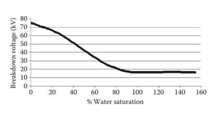
The breakdown voltage (BDV) of oil refers to the point at which insulating oil loses its dielectric strength and begins to conduct electricity, potentially leading to failure in electrical systems. In systems like transformers, insulating oil plays a critical role in preventing electrical discharges by providing both insulation and cooling. A BDV test is essential for evaluating the quality and effectiveness of the oil. The higher the BDV, the better the oil can resist electrical breakdown, ensuring the safety and efficiency of the system.
What is the breakdown voltage of oil, and why is it important in electrical systems?
The breakdown voltage (BDV) of oil is the maximum voltage at which the insulating properties of the oil fail, causing it to conduct electricity. This is critical in systems like transformers, where transformer oil is used as an insulator. If the BDV of the oil is low, it can lead to electrical failures, short circuits, and equipment damage. Testing and maintaining the BDV ensures that the oil can effectively insulate electrical components and prevent catastrophic breakdowns.
How is the breakdown voltage of oil measured, and what are the typical test methods?
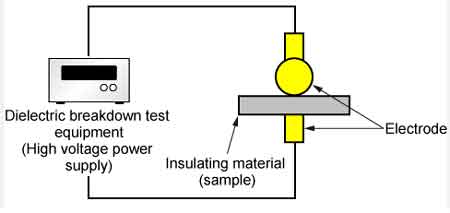
The breakdown voltage test is performed by placing an oil sample between two electrodes immersed in the oil at a specific distance, known as the specific gap. A gradually increasing voltage is applied until the oil fails and allows current to flow between the electrodes. The voltage at which this occurs is recorded as the BDV. This test is crucial in assessing the dielectric strength of the oil. The BDV test is typically conducted according to industry standards to ensure accurate and reliable results.
What factors affect the breakdown voltage of insulating oil?
Several factors can affect the breakdown voltage of insulating oil. Conducting impurities, such as moisture, dust, and other contaminants, can significantly lower the BDV of the oil. Over time, oil exposed to high temperatures, oxidation, and electrical stress can degrade, reducing its dielectric properties. Additionally, the presence of gases dissolved in the oil, as well as the condition of the oil's molecular structure, can affect its ability to insulate. Proper maintenance and regular testing help ensure that these factors are kept in check.
What are the typical breakdown voltage values for transformer oil?
The typical breakdown voltage values for transformer oil range from 30 kV to 60 kV, depending on the quality of the oil and its use in the transformer. New transformer oil generally has a higher BDV, while older, degraded oil can have a significantly lower value. Industry standards set minimum acceptable BDV values to ensure that the oil can maintain its insulating properties under operating conditions. Regular testing is necessary to monitor the oil’s performance and ensure it meets the required specifications.
How can the breakdown voltage of oil be improved or maintained?
Maintaining and improving the breakdown voltage of insulating oil involves regular testing and filtration. Removing conducting impurities such as moisture and dissolved gases can help increase the BDV. Proper storage and handling of the oil are also critical in preventing contamination. In some cases, reconditioning the oil by removing contaminants and restoring its dielectric properties can extend its useful life. Periodic BDV tests ensure that the oil continues to meet the necessary dielectric standards, safeguarding the electrical system from potential failure.
The breakdown voltage (BDV) of oil is a key parameter in maintaining the safety and efficiency of electrical equipment, particularly in transformers. By regularly testing and ensuring that the oil retains its dielectric strength, engineers can prevent costly electrical failures and extend the lifespan of the equipment. Proper maintenance and testing of transformer oil through BDV tests are essential to keeping systems operating safely and effectively.
Download Our FREE Dielectric Fluids Handbook
In this latest volume, we delve deep into the evolving field of transformer testing, focusing on advanced methods, technologies, and best practices essential for ensuring the optimal performance and longevity of electrical transformers. As transformers remain a critical component of power transmission and distribution systems, accurate testing is paramount to maintain the integrity of the electrical grid and prevent costly failures.
This handbook offers a comprehensive guide to the latest transformer testing techniques, from traditional diagnostic tests to cutting-edge technologies such as partial discharge monitoring, oil analysis, and advanced condition-based testing methods. We also explore the growing role of digitalization and real-time data analytics in transforming transformer testing, enabling utilities to detect potential issues before they lead to system outages.
Through expert insights, case studies, and step-by-step testing procedures, Volume 7 equips engineers, utilities, and industry professionals with the knowledge and tools to conduct thorough and effective transformer testing. Whether you’re focused on routine maintenance, failure prevention, or asset management, this volume is an invaluable resource for ensuring your transformers continue to operate safely and efficiently in today’s increasingly complex energy landscape.
Latest Dielectric Fluids Articles
Advancements in Dissolved Gas Analysis: Data Quality
Advancements in DGA data quality enable precise transformer monitoring, dissolved gas analysis, and predictive maintenance through calibrated sensors, IEC 60599/IEEE C57.104 harmonization, machine-learning analytics, anomaly detection, and IEC 61850-integrated SCADA data integrity.
What Are Advancements in DGA Data Quality?
Enhanced DGA data quality strengthens transformer diagnostics via calibrated sensors, aligned standards, and analytics.
✅ On-line oil monitors with auto-calibration and drift correction
✅ IEC 60599/IEEE C57.104 harmonized thresholds and diagnostics
✅ ML-based anomaly detection and condition-based maintenance
Introduction
There is more to DGA interpretation than comparing the latest gas concentrations to limits in a table or plotting them in a triangle or pentagon to identify the apparent fault type. We have found that the whole DGA history of a transformer must be considered when interpreting its most recent DGA results.
Trend evaluation and accurate assessment of short-term changes require accuracy and low measurement variability of gas data. Data quality problems must be recognized and dealt with before an interpretation is attempted. Below we point out some of the most common data quality issues. For broader context on diagnostics, the primer on dissolved gas analysis outlines core fault signatures, typical gas sources, and interpretation pitfalls.
Understanding how oil and paper behave electrically is foundational, and the summary of fundamental dielectric characteristics helps explain why certain gases trend together over time.
Data management
As a result of the historical importance of DGA data, proper organization and preservation of DGA data are extremely important. In addition to archiving the lab reports, keep the data in tabular form in a database or, for small volumes of data, a spreadsheet. A well-organized database supports sorting and filtering for graphical and statistical analysis.
Use a unique and permanent ID to identify transformers, oil compartments, and the oil sample data belonging to them. Substation and unit number are not a suitable ID, for the same reason that the dentist doesn’t identify you by your department and job title. Large transformer fleets may require company-assigned asset numbers to avoid possible serial number duplication across manufacturers.
Disciplined chain-of-custody practices provide correct IDs of transformers and compartments to be sampled, ensure that oil samples are labeled correctly, and guarantee that analysis results returned by the lab are attributed to the right transformers and oil compartments. Integrating laboratory reports with a structured repository is easier when guided by practical notes on transformer oil analysis data formats and decision thresholds.
For sampling logistics and labeling discipline, operations teams can review guidance on oil in transformers to align maintenance practices with data management goals.
Data inconsistency or inaccuracy
Gas loss that is deliberate, such as by head space pressure regulation or use of a desiccant breather, needs to be accounted for as discussed in our other article [1]. Unintended gas leakage from a transformer – often detectable by a O2/N2 ratio persistently above 0.2 when it should be lower – should be remedied as soon as possible, both to keep DGA effective and to prevent moisture ingress. After oil degassing, it is advisable to exclude samples from DGA interpretation for 6-12 months due to the false upward trends created by diffusion of gases from winding paper into the bulk oil.
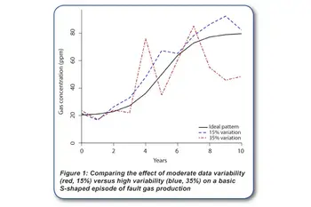
Accuracy and repeatability of gas data are only partly up to the laboratory. Unrepresentative oil samples can lead to inconsistent and highly variable gas data regardless of the quality of laboratory measurements. A study by a large USA electric utility [2] shows that using extra care and a moisture / temperature probe to ensure collection of representative oil sample can reduce data variability considerably. The figure (Figure 1) illustrates the effect of moderate variability (±15%) versus high variability (±35%) on the data from a basic S-shaped gassing event.
Moderate variability is experienced with consistently good sampling practice and a good laboratory. High variability is easily attainable if there is a problem with sampling practices. Recent field case studies on advancements in dissolved gas analysis discuss accounting for gas loss, diffusion effects, and sampling bias.
When evaluating short-term changes following maintenance, further techniques described in advancements in DGA interpretation can reduce false alarms by emphasizing trend shape over single-point limits.
The table provides a summary of some common data quality problems. Sections 5.1 and 5.2 of IEEE C57.104-2019 [3] contain a detailed discussion of data quality assessment. For paper-aging diagnostics specifically, insights on the CO/CO2 ratio in DGA clarify when cellulose decomposition is the likely source.
References
[1] “Advancements in Dissolved Gas Analysis: Accounting for Gas Loss,” Electricity Today, March 2020
[2] T. Rhodes, “Using field moisture probes to ensure drawing a representative oil sample,” in 82nd Annual International Doble Client Conference, Doble Engineering Company, March 2015.
[3] “IEEE Guide for the interpretation of gases dissolved in mineral oil filled transformers”, IEEE Std C57.104-2019.
Related Articles
Advancements in Dissolved Gas Analysis Explained
Advancements in dissolved gas analysis2 deliver smarter transformer condition monitoring, predictive maintenance, and fault diagnostics via online sensors, IEC 60599 methods, Duval Triangle analytics, and machine learning for grid reliability.
What Are Advancements in Dissolved Gas Analysis2?
Modern DGA methods using online sensors, IEC standards, and AI to diagnose transformer faults proactively.
✅ Real-time gas monitoring via online chromatographs and sensors
✅ AI and Duval Triangle enhance fault classification accuracy
✅ Standards-based analysis per IEC 60599 supports maintenance
One of the most important steps when looking at DGA data is to decide whether the data support the existence of a fault that is actively breaking down the insulation before you try to use a triangle, pentagon, or gas ratio method to identify a fault type. Otherwise, you are diagnosing random measurement noise, not the transformer. Conventional methods assign limits to each of the gases to detect and assess abnormal gas formation. Formerly it was common practice to add gas concentrations together to get total dissolved combustible gas (TDCG). The hope was to simplify the task of detecting abnormal gas production and interpreting rates of change. This, however, was equivalent to counting U.S. Dollars, Mexican Pesos, Bitcoins, and Canadian Loonies and thinking that the sum represented “value”. To reduce false positives from sensor drift and sampling errors, recent work on advancements in DGA data quality outlines practical controls for sampling, calibration, and trending.
Electrical Transformer Maintenance Training
Substation Maintenance Training
Request a Free Training Quotation
Chemistry dictates that each gas we observe requires a different amount of energy to break away from the original insulating material. Instead of trying to interpret several individual gas concentrations, why not follow the energy associated with the gassing? The energies required to form the gas can be weighted by the gas concentrations and added up.
For a grounding in principles and typical fault signatures, see this overview of dissolved gas analysis techniques and their diagnostic use.
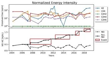
This idea of using standard heats of formation of fault gases for DGA was worked out in Jakob et al. 2012 and demonstrated to be an improvement compared to TDCG and other gas concentration sums. Soon after that, chemist Fredi Jakob realized that it would be better to create a fault energy index, which he called normalized energy intensity (NEI), to represent the influence of an internal fault on the insulating oil. That idea was presented in Jakob & Dukarm 2015, where it was shown that NEI was very useful for trending fault severity and not partial to any particular fault types. The figure illustrates how trending cumulative NEI simpli.es the detection of suspicious gas production. For additional context on modern interpretation frameworks, review these advancements in dissolved gas analysis that compare energy-based indices with classical ratio methods.
NEI, now renamed NEI-HC, is based on the low molecular weight hydrocarbon gases generated from cracking mineral oil. Another fault energy index, called NEI-CO, is based on the carbon oxide gases formed by pyrolysis of cellulose in paper insulation. The formulas for NEI-HC and NEI-CO are shown in Equations (1) and (2) below. Since each set of gases comes from a different insulation material, you can assess and track which faults are affecting paper, hot metal in the oil, or both. That knowledge can help point to the root cause and better estimate the severity of the problem. When paper degradation is suspected, trends can be corroborated with guidance on the CO/CO2 ratio in DGA to strengthen evidence for thermal versus oxidative effects.
Because NEI-HC derives from oil cracking, selecting and maintaining a high-quality transformer insulating oil is essential for resilient performance under thermal stress.
NEI-HC = 77.7[CH4] + 93.5[C2H6] + 104.1[C2H4] + 278.3[C2H2] / 22400 (1)
NEI-CO = 101.4[CO] + 30.19[CO2] / 22400 (2)
The highest heat of formation for the hydrocarbons is C2H2 and for carbon oxides it is CO. This physically confirms the general intuition that these gases are the most concerning to see in transformer DGA. These concerns underscore why routine transformer oil analysis remains central to risk-based maintenance planning.
You can trend fault energy indices to identify gassing episodes and relate them to external events such as through faults, maintenance work orders, and load changes to help determine what might have triggered the gassing. Also, you can track the cumulative energy over the history of the transformer to counteract effects of gas-loss (see previous article in this series). Interpreting those trends alongside the unit's fundamental dielectric characteristics helps differentiate benign load-related gassing from insulation distress.
Related Articles
Advancements in Dissolved Gas Analysis: Investigating Failure Cases
Advancements in dissolved gas analysis3 leverage online DGA sensors, AI-driven diagnostics, IEC 60599 models, and predictive maintenance workflows to enhance transformer condition monitoring, fault detection, and reliability through real-time trend analysis and anomaly detection.
What Are Advancements in Dissolved Gas Analysis3?
Modern DGA methods using online sensors, analytics, and standards to improve transformer fault detection.
✅ Online multi-gas sensors enable real-time transformer health insights
✅ AI models apply IEC 60599 ratios for early fault classification
✅ Cloud dashboards support predictive maintenance and compliance
INTRODUTION
Dissolved gas analysis (DGA) provides the early warning radar view of a transformer fleet with a non-intrusive screening process for early identification of problematic transformers. Suspicious transformers can be subjected to more invasive and costly physical testing to determine the actual condition and service readiness of the transformer. Three case histories illustrate the usefulness of recent innovations in transformer DGA, especially when there is gas loss. Two of the example transformers failed in service, to the surprise of the utilities responsible for them since they did not exceed conventional DGA limits. In the other case, the utility is urgently looking for a replacement unit based on very concerning DGA results. For these examples we will use some of the techniques presented earlier in this series of articles. We will also introduce some new concepts to be covered in greater detail in later articles of the series. For example, we will use cumulative gas data to compensate partially for gas loss. Gas loss occurs either by leakage or by gas blanket pressure regulation, which releases head space gas to reduce pressure and adds nitrogen to raise pressure. The IEEE C57.104 transformer DGA guide, from 1978 until the latest version in 2019 [1], has never adequately addressed the problem of gas loss, which can delay or prevent limits-based detection of fault gas production. We will also use normalized fault energy indices (NEI), which represent the energy required to generate the observed fault gases from the paper and oil insulation. This will illustrate a new paradigm for DGA interpretation, described briefly in Annex F of IEEE C57.104-2019, that is less focused on gas concentrations in favor of fault energy related to defects, malfunctions, and excessive stress. Rather than display long tables of numbers, we present the DGA data for the examples graphically in the form of three stacked charts for each example. The top chart is for the hydrocarbon gas fault energy index, NEI-HC, representing fault energy affecting the mineral oil. The upper trend line is cumulative NEI-HC, while the lower one is NEI-HC as calculated for each oil sample. Boxes are drawn on the cumulative NEI trend line to highlight time intervals when significant fault gas production appears to be happening. The middle chart is for the carbon oxide gas fault energy index, NEI-CO, representing fault energy affecting paper insulation in a similar fashion. The bottom chart is for the CO/CO2 gas concentration ratio as calculated for each oil sample. For background on methodology, see dissolved gas analysis fundamentals for context.
Recent industry coverage of advancements in dissolved gas analysis highlights tools that support this fault energy approach.
Example #1
The transformer in Example #1 had a long NEI-CO gassing event, suggesting gradual thermal degradation of insulating paper. The up and down motion of NEI-CO (bottom line in the NEI-CO chart) is not just noise in the data – it reflects fault gas production with gas loss from pressure regulation connected with thermal cycling in a hot climate and a 6-month sampling frequency. The cumulative NEI-HC trend has two distinct gassing events with IEC fault types S and O respectively, indicating thermal fault gas production below 250°C. There are corresponding large increases in the CO/CO2 ratio, suggesting charring of winding paper insulation. The method of interpreting percent changes in the CO/CO2 carbon oxide gas ratio (sometimes inverted as CO2/CO) was worked out by Chris Rutledge and Randy Cox as a way of locating the source of carbon oxide gas production [2, 3]. Large percent increases in CO/CO2 are associated with charring of winding insulation paper. Of course, degradation of winding insulation is of great interest. When this transformer tripped due to turn-to-turn arcing, it was a complete surprise to the utility. The transformer never exceeded IEEE C57.104-2008 gas concentration limits, nor did it exceed the IEEE C57.104-2019 rate of change limits. The Example #1 charts, providing evidence of continual paper degradation with two significant episodes of a low range thermal fault affecting winding insulation, would have led an experienced engineer to flag this unit for investigation. The concern would be heightened by the realization that the severity of the problem may have been underestimated due to gas loss. A post-mortem revealed extensive charring of the paper winding insulation. Additional guidance on interpreting the CO/CO2 trend is summarized in CO/CO2 ratio practices for practitioners.
Example #2
The transformer in Example #2 appears to be in very precarious condition, and the utility responsible for it is planning to replace it quickly. The gassing event beginning in 2012 appeared to indicate a T2 hot spot affecting both paper insulation (NEI-CO) and oil (NEI-HC). Gas loss due to pressure regulation is evident from the saw-tooth patterns in NEI-HC and NEI-CO during the event as gases were generated and lost. The cumulative NEI trends show that there was rapid fault gas production, although the true extent of it can’t be known. The percent increase in the CO/CO2 ratio at the time was extreme, suggesting that winding paper was affected. Gaseous evidence of the problem dissipated in subsequent years as gas loss lowered the NEI levels and flattened the cumulative NEI. Recently a new event, classified as a D1 type fault, or low-energy electrical discharge, has been active, once again affecting the paper as indicated by a simultaneous rise in NEI-CO. The current hypothesis is that the fault starting in 2012 may have charred paper insulation between windings. Weak turn-to-turn discharges started later in 2018. The lack of movement in the CO/CO2 ratio during the most recent NEI event provides no information as to the location of paper involved in the recent event. If the problem is localized charring of winding paper between turns resulting in the onset of electrical sparking, CO and CO2 production would cease after the paper in that area was completely charred. Thus, the lack of recent carbon oxide gas production could be very concerning. Gas concentrations during the 2012 event only reached IEEE status code 2, soon returning back to status code 1 due to gas loss. Damage to the transformer did not magically repair itself, despite a de-escalation to a lower status code. Complementary transformer oil analysis procedures can help corroborate DGA findings during such events.
Improved sampling, screening, and lab controls described in advancements in DGA data quality strengthen trending when gas loss complicates interpretation.
Example #3
The Example #3 transformer had a persistent T2 thermal problem with long, steady NEI-HC and NEI-CO trends. In 2013, the NEI-HC trend accelerated sharply, indicating that something may have changed for the worse. For a while, acetylene production changed the fault type to a D1 electrical discharge. The gases other than acetylene remained below IEEE C57.104-2008 limits. Later the acetylene dissipated as the original trend resumed. The NEI-CO graph indicates that starting in 2013 there was an accelerating rate of change in cumulative NEI-CO leading up to the time of failure. The sawtooth pattern in the measured NEI-CO during that time can be attributed to gas blanket pressure regulation. Just as the unit reached status level 2 by exceeding the IEEE C57.104-2008 heat gas limits, the unit failed. The transformer never reached status level 3 except for the bump in acetylene during the 2013 event. The CO/CO2 ratio did not change much since 2006. It is likely that CO loss via gas blanket pressure regulation was sufficient to keep the CO/CO2 ratio relatively constant even though, as the upward trend in NEI-CO indicates, there was significant production of carbon oxide gases. Thus, in this case DGA did not provide any indication of whether winding paper insulation was being affected by the T2 and D1 faults. The fact that the transformer failed while NEI-CO was accelerating permits us to suspect that the problem was located in the windings, specifically on the outer layers where oil can circulate. Understanding oil behavior in transformers clarifies how thermal faults drive hydrocarbon gas trends.
Conclusions
The way of interpreting DGA demonstrated above requires tracking fault energy affecting liquid and solid insulation over the whole history of the transformer. Data management and good data quality are extremely important for early detection and accurate assessment of problems. DGA results for the most recent one or two oil samples are not sufficient to detect or diagnose the problems discussed in the above examples. These case histories show that waiting for a 90th percentile outlier in the DGA data is not a dependable method for identifying transformers in trouble. Waiting to see large concentrations or rates of increase of gas in any transformer before reacting is like waiting to read the license plate before getting out of the way of an oncoming car. Gas loss can keep gas levels and rates of change deceptively low, even when there is significant production of fault gas. A DGA report is a snapshot of an evolving and dynamic process, like a frame of a movie. To understand the current results properly, it is necessary to consider them in the context of as many past results as possible. The outcome of DGA interpretation is an assessment of whether the transformer appears to be producing fault gas, and if it does, to support further investigation or action by trying to guess the nature of the problem and assess risk. Usually DGA cannot provide a definite verdict on the transformer’s condition except to say whether or not it is gassing. That is reflected in the change of language in IEEE C57.104-2019, which has “status” codes instead of “condition” codes. For reliable information about a transformer’s condition, physical testing is usually required. In future articles, we will discuss the CO/CO2 ratio in more detail. We will also discuss severity assessment for gassing events and hazard factors for quantitative risk assessment. A grounding in fundamental dielectric characteristics also helps connect observed gases to insulation physics.
References.
- “IEEE Guide for the interpretation of gases dissolved in mineral oil filled transformers,” IEEE Std C57.104, editions 1978, 1991, 2008, and 2019.
- C. Rutledge and R. Cox, “A comprehensive diagnostic evaluation of power transformers via dissolved gas analysis,” 2016 IEEE/PES Transmission and Distribution Conference and Exposition (T&D), Dallas, TX, 2016, pp. 1-5, doi: 10.1109/TDC.2016.7519996.
- R. Cox, ‘“Categorizing Faults in Power Transformers via Dissolved Gas Analysis,” NETA World Journal, Spring 2020, pp. 64–68.
Related Articles
Transformer Cooling
Transformer cooling enhances thermal management via oil-immersed and air-cooled systems, radiators, fans, and pumps. Methods like ONAN, ONAF, and OFAF reduce temperature rise, limit insulation aging, and improve efficiency under varying load.
What Is Transformer Cooling?
Transformer cooling removes heat from windings and core via oil or air circulation to control temperature and slow aging.
✅ Common types: ONAN, ONAF, OFAF, OFWF for various ratings.
✅ Components: radiators, fans, oil pumps, heat exchangers.
✅ Benefits: lower temperature rise, higher efficiency, longer life.
A little energy lost in a transformer must be dissipated as heat. Although this energy is but a small portion of the total energy undergoing transformation, it becomes quite large in amount in transformers of larger kVA ratings. To maintain efficiency and life expectancy the transformer's cooling system needs to be operating at peak performance. For dry-type transformers, the ventilation system of the room should be inspected to make sure it is operating efficiently. For forced air-cooled systems, the fan motors should be checked for proper lubrication and operation. Water-cooled systems must be tested for leaks and proper operation of pumps, pressure gauges, temperature gauges and alarm systems.
In liquid-filled designs, the choice and maintenance of oil in transformers directly influence heat removal performance and long-term reliability.
When a liquid coolant is used its dielectric should be tested. Water in the coolant will reduce its dielectric strength and the insulation quality. In cases where the dielectric strength of the coolant is reduced significantly, conducting arcs may develop causing short-circuits when the transformer is energized. A standard oil dielectric test involves applying high voltage to a sample taken from the transformer and recording the voltage at which the oil breaks down. If the average breakdown voltage is less than 20 kilovolts, the oil will need to be filtered until a minimum average breakdown of 25 kilovolts is achieved. Technicians often reference breakdown voltage of oil guidelines to interpret test results and schedule remediation.
Comprehensive transformer oil analysis can reveal moisture ingress, dissolved gases, and particulate contamination before failures occur.
Oil-insulated transformers use mineral oil for cooling. This oil is thin enough to circulate freely and does a good job of providing insulation between the transformer windings and the core. It is however subject to oxidation and if any moisture enters the oil, its insulating value is substantially reduced. In addition, mineral oil is flammable and therefore should not be located near combustible materials indoors or outdoors. In critical applications, selecting a high-quality transformer insulating oil mitigates oxidation, moisture effects, and thermal aging.
These behaviors align with the fundamental dielectric characteristics that govern insulation performance under electrical and thermal stress.
There are several types of transformer oil cooling solutions:
- oil air
- forced oil
- oils water
- oil natural
- air forced
- heated oil
- oil forced
- natural
In practice, each configuration must be evaluated alongside the properties of the chosen dielectric fluid to balance cooling effectiveness, safety, and service life.
Outdoor liquid-cooled transformers usually use mineral oil, and liquid cooled transformers for inside use are filled with a synthetic liquid that is nonflammable and nonexplosive. Synthetic oil coolants must be handled with care as they sometimes cause skin irritations. One type, askarelinsulated transformers used in past years contained polychlorinated biphenyls (PCBs), which are known to cause cancer. Askarel has been banned by the Environmental Protection Agency and its use as a transformer coolant is being phased out. However, askarel coolants are still found throughout the electrical industry in older transformers and direct contact with them should be avoided. The NEC still contains provisions for installing askarel transformers. The following is a list of the different types of liquid-filled transformers recognized by the NEC:
Facility engineers should review application requirements, fire codes, and material compatibility when selecting oil for transformers to ensure compliance and dependable operation.
- Oil-Insulated--uses chemically untreated insulating oil
- Askarel—uses nonflammable insulating oil
- Less-Flammable Liquid-Insulated--uses reduced flammable insulating oil
- Nonflammable Fluid-Insulated--uses noncombustible liquid
Related Articles

Dielectric Fluid
Dielectric fluid is an insulating liquid used in electrical equipment like transformers and capacitors to prevent arcing, dissipate heat, and ensure system reliability. It offers high dielectric strength, thermal stability, and moisture resistance for safe operation.
What is Dielectric Fluid?
Dielectric fluid is a critical component in the operation and safety of electrical equipment, especially transformers and high-voltage switchgear.
✅ Provides electrical insulation and prevents arcing in high-voltage systems.
✅ Offers excellent thermal conductivity to dissipate heat.
✅ Protects components from moisture and contamination.
For industrial electricians, understanding their role in insulation, cooling, and arc suppression is essential for ensuring system reliability and preventing electrical failures. Let's review the properties, types, and maintenance requirements of dielectric fluids, providing practical insights into how they support energy efficiency, equipment longevity, and fire safety. Readers will learn about testing procedures, contamination risks, and how proper fluid management can minimize downtime and enhance overall electrical system performance. An oil-filled transformer relies on dielectric fluid to provide both insulation and cooling, ensuring safe and efficient operation.
Electrical Transformer Maintenance Training
Substation Maintenance Training
Request a Free Training Quotation
Applications in Electrical Equipment
In the realm of electrical equipment, insulating fluids are indispensable. They serve as both insulating and cooling agents, safeguarding systems from electric discharges while effectively dissipating heat. High-voltage applications, such as transformers, capacitors, and cables, rely heavily on these fluids to maintain stability and reliability. By preventing electric breakdown in these critical components, dielectric fluid ensures the longevity and efficiency of power distribution networks, which are the backbone of modern energy systems. The quality of transformer oil is crucial because its dielectric properties directly affect breakdown voltage and reliability.
Role in Immersion Cooling
The role of dielectric fluid in immersion cooling has gained prominence with the rise of data-intensive industries. Immersion cooling involves submerging electronic components in a thermally stable dielectric liquid to enhance heat transfer and reduce energy consumption. This technique is particularly advantageous in data centers, where efficient cooling solutions are essential. By dissipating heat more effectively than traditional air-cooling methods, dielectric fluid enables high-performance computing systems to operate at optimal levels while minimizing their environmental impacts. Understanding the role of transformer core and its interaction with insulating fluids can optimize cooling and extend transformer lifespan.
Comparison with Mineral Oils
A frequent comparison in the industry is between dielectric fluid and traditional mineral oil. While both serve as insulators and coolants, advanced dielectric fluid surpasses mineral oils in terms of thermal stability, oxidation resistance, and eco-friendliness. In high-voltage applications, \fluids offer lower operating temperatures and improved system reliability, reducing failure rates and extending service life. These properties make them an ideal choice for industries seeking to strike a balance between performance and sustainability.
Comparison of Dielectric Fluids
| Fluid Type | Key Properties | Advantages | Limitations |
|---|---|---|---|
| Mineral Oil | Moderate dielectric strength, good cooling, low cost | Widely available, proven track record | Low fire point, poor biodegradability |
| Natural Ester | High dielectric strength, high fire point (>300°C) | Biodegradable, excellent moisture tolerance | Higher cost, potential oxidation if unmanaged |
| Synthetic Ester | High thermal stability, excellent oxidation resistance | Long service life, superior high-temperature performance | Expensive, less eco-friendly than natural esters |
| Nanofluids | Enhanced dielectric strength and heat transfer via nanoparticles | Improved cooling, reduced aging, and emerging technology | Still experimental, higher production cost |
Types of Dielectric Fluids – Mineral Oil, Natural Ester, Synthetic Ester, Emerging Nanofluids
Dielectric fluid is categorized into several types, each with distinct properties and applications. Mineral oil has been the traditional choice due to its low cost and reliable insulation; however, it has limitations, including low flash points and environmental concerns. Natural ester fluids, derived from vegetable oils, offer high biodegradability, excellent moisture absorption, and fire safety advantages with fire points exceeding 300°C. Synthetic esters provide superior oxidation stability and thermal performance, making them suitable for high-load and high-temperature applications. Emerging nanofluids, enhanced with nanoparticles such as graphene or titanium dioxide, are at the forefront of innovation, offering improved thermal conductivity, higher dielectric strength, and enhanced aging resistance compared to conventional fluids. Regular testing of transformer oil filling is essential to avoid contamination and maintain high dielectric strength.
Material Compatibility & Impregnation – Testing Standards, Handling Guidance, Temperature Considerations
The interaction of dielectric fluids with insulation materials, gaskets, and seals plays a vital role in system performance. Certain fluids can cause swelling, shrinkage, or chemical degradation of elastomer-based gaskets, leading to leaks or compromised insulation. Modern ester fluids often require gasket materials that are highly resistant to hydrolysis and oxidation, such as nitrile or fluorocarbon elastomers, which offer superior stability compared to standard rubber seals.
Solid dielectrics, like pressboard or paper insulation, are directly affected by fluid absorption and impregnation. A properly selected fluid not only insulates but also strengthens these materials by filling microscopic voids and preventing moisture ingress. Poor fluid-material compatibility can reduce dielectric strength and lead to premature equipment failure.
The impregnation process, often carried out using vacuum-pressure cycles, ensures that the fluid thoroughly saturates the cellulose insulation. Vacuum impregnation removes trapped air and moisture before fluid introduction, improving dielectric performance and reducing the risk of partial discharges. Heating the fluid slightly during impregnation enhances its flow properties and ensures deep penetration. Standards like ASTM D3455 are used to verify material compatibility, while strict handling guidelines prevent contamination and degradation during storage. Proper transformer insulation depends on the fluid’s ability to prevent arcing and maintain thermal stability under load.
Material Compatibility and Impregnation Guidelines
| Aspect | Key Details | Recommended Standards/Tests | Notes and Best Practices |
|---|---|---|---|
| Gasket Compatibility | Evaluates swelling, shrinkage, and chemical stability of elastomers | ASTM D3455 (Compatibility Testing) | Use nitrile or fluorocarbon gaskets for ester-based fluids |
| Solid Dielectrics | Interaction with pressboard, paper, or cellulose insulation | IEC 60296 (Insulating Liquids) | Ensure low-moisture fluids to prevent insulation breakdown |
| Impregnation Process | Saturation of solid insulation with dielectric fluid | Vacuum-Pressure Impregnation Methods | Perform multi-cycle vacuum drying for optimal saturation |
| Handling Guidance | Preventing contamination during storage and transfer | ASTM D923 (Sampling Insulating Liquids) | Use sealed containers and moisture-proof handling systems |
| Temperature Control | Managing viscosity and flow during impregnation | ASTM D3487 (Transformer Oils) | Preheat fluid slightly (40–60°C) for better impregnation |
Influence on Gaskets and Dielectric Materials
The compatibility of insulating fluids with gaskets, seals, and solid dielectric materials is critical for the long-term reliability of electrical equipment. Certain fluids can cause swelling, shrinkage, or chemical degradation of elastomer-based gaskets, leading to leaks or compromised insulation. Modern natural and synthetic ester fluids often require gasket materials that are highly resistant to hydrolysis and oxidation, such as nitrile or fluorocarbon elastomers, which offer superior stability compared to standard rubber seals.
Solid dielectrics, like pressboard or paper insulation, are directly affected by fluid absorption and impregnation. A properly selected fluid not only insulates but also strengthens these materials by filling microscopic voids and preventing moisture ingress. Poor fluid-material compatibility can reduce dielectric strength and lead to premature equipment failure.
Performance Metrics & Diagnostics – Presenting Typical Values, Standards, and Testing Procedures
Key performance metrics for insulating fluids include dielectric breakdown voltage, moisture content, viscosity, thermal conductivity, and flash point. Testing standards such as IEC 60156 (breakdown voltage), ASTM D877/D1816 (oil testing), and IEC 60247 (dielectric dissipation factor) are widely used to evaluate fluid health. Dissolved Gas Analysis (DGA) is another critical tool that monitors the condition of transformer oils by detecting gases produced during thermal or electrical faults.
Regular diagnostic testing allows early detection of contamination, oxidation, or moisture ingress. By tracking these values, maintenance teams can take corrective action before failures occur, extending equipment life and ensuring uninterrupted service.
Innovations – Nanofluids and Sustainability Trends
The development of nanofluids is revolutionizing dielectric technology. By suspending nanoparticles like Al₂O₃, SiO₂, or graphene in base fluids, engineers have achieved significant improvements in dielectric strength, heat transfer, and thermal stability. These advanced fluids operate under higher electrical stress while maintaining lower temperatures, leading to greater reliability and efficiency.
Sustainability trends favor the use of natural and synthetic esters due to their biodegradability, reduced greenhouse gas footprint, and compliance with modern fire safety and environmental standards. As industries shift toward eco-friendly energy solutions, insulating fluids are being optimized to deliver both performance and environmental benefits. Monitoring breakdown voltage helps evaluate the condition of dielectric fluids and ensures they can withstand high voltages.
Practical Guidance – Selection Criteria Based on Fire Safety, Environmental Regulations, Maintenance Strategy, and Transformer Design Optimization
Choosing the right fluid involves striking a balance between technical performance and safety and environmental requirements. Fire safety considerations often favour natural esters, which have much higher fire points than mineral oils. Environmental regulations are increasingly encouraging fluids with low toxicity and high biodegradability to minimize ecological risks. A maintenance strategy also plays a role; fluids with greater oxidation stability and moisture tolerance can extend maintenance intervals, thereby lowering overall operating costs. Ultimately, transformer design optimization—including heat transfer requirements, viscosity, and load profiles—may dictate which fluid type offers the best efficiency and long-term reliability. Core parts of transformer components are submerged in dielectric fluid to minimize electrical discharge and control temperature.
Frequently Asked Questions
What are the Critical Components for Industrial Electricians?
Understanding the intricacies of electrical power distribution transformers is paramount for industrial electricians. These vital components play a pivotal role in the efficient and reliable delivery of electrical power to industries and businesses worldwide. By delving into the fundamental concepts of transformer operation, types, maintenance, and future trends, industrial electricians can gain valuable insights to optimize electrical systems, troubleshoot potential issues, and ensure a reliable and uninterrupted power supply. Insulating oil is essential for preventing electric discharges in high-voltage equipment. By immersing electrical components in these fluids, manufacturers can significantly reduce the risk of arcing and short circuits. Techniques like immersion cooling utilize insulating oil to effectively dissipate heat generated by high-power components, ensuring optimal performance and longevity.
What are the key characteristics of an effective electrical insulating oil?
The primary function of electrical insulating oil is to provide electrical insulation. Filling the gaps between electrical components prevents arcing and short circuits, which can lead to equipment failure and potentially hazardous situations. Additionally, dielectric fluid excels at dissipating heat generated by electrical equipment, ensuring optimal performance and longevity.
What are the most common types of electrical insulating oil, and where are they used?
Electrical insulating oil comes in various types, each with its unique properties and applications. Historically, mineral oil has been the most commonly used dielectric fluid, offering a balance of cost-effectiveness and reliability. However, its environmental impact and susceptibility to degradation have led to the development of alternative options. Synthetic esters, for instance, provide superior dielectric properties, thermal stability, and biodegradability, making them a more environmentally friendly choice. Silicone fluids, renowned for their exceptional thermal stability and resistance to oxidation, are frequently employed in high-voltage applications where reliability and long-term performance are crucial. While perfluorinated fluids offer exceptional dielectric strength and thermal stability, their high cost and potential environmental impact limit their widespread use.
The performance of electrical insulating oil is influenced by several factors. A crucial factor is dielectric strength, which measures the fluid's ability to withstand high voltages without breaking down. Additionally, the fluid's thermal stability is essential for maintaining its insulating properties under varying temperature conditions. Chemical stability is also important, as it ensures the fluid's resistance to degradation and oxidation. Furthermore, a low flash point and flammability rating are crucial for safety, especially in enclosed environments. Lastly, the environmental impact of the fluid, including its biodegradability and toxicity, is becoming increasingly significant in the selection of dielectric fluids.
How does transformer oil impact sustainability?
Regular testing and maintenance are crucial to ensure the optimal performance of insulating oil. These tests evaluate critical properties, including dielectric strength, moisture content, and acidity level. By monitoring these parameters, engineers can identify potential issues and take corrective actions to prevent equipment failures. This proactive approach helps maintain the reliability and safety of electrical systems.
Dielectric fluid is an essential component in high-voltage electrical systems. They provide critical insulation and cooling properties, preventing electrical breakdowns and ensuring the reliable operation of equipment. By understanding the properties and applications of different dielectric fluids, engineers and technicians can select the most suitable fluid for specific applications and optimize system performance.
Related Articles
Dissolved Gas Analysis Of Transformer Oil
Dissolved Gas Analysis (DGA) is a key diagnostic tool for transformers, evaluating dissolved gases in insulating oil to identify overheating, arcing, partial discharge, and insulation breakdown. It enables predictive maintenance, improves power system reliability.
What is Dissolved Gas Analysis?
Dissolved Gas Analysis is a diagnostic method that evaluates gases in transformer insulating oil to identify electrical faults and ensure reliable operation.
✅ Detects partial discharge, arcing, and overheating
✅ Guides predictive maintenance and fault prevention
✅ Improves transformer reliability and system safety
DGA is a crucial tool for electrical engineering and maintenance professionals, providing vital insights into the health of transformers and other high-voltage assets. By detecting gases produced during insulation degradation or electrical faults, it offers early warning signs of potential failures. Proactive detection through DGA allows utilities and industries to prevent unplanned outages, extend equipment lifespan, and strengthen system reliability. As a cornerstone of condition-based maintenance, mastering DGA is essential for maintaining high-performance electrical infrastructure. Understanding dissolved gas analysis begins with the role of dielectric fluids, as the composition of transformer oil directly influences gas formation and the accuracy of fault detection.
Electrical Transformer Maintenance Training
Substation Maintenance Training
Request a Free Training Quotation
Transformer Fault Diagnosis
One of the key applications of DGA is transformer fault diagnosis. Under normal operating conditions, only trace gases form. During faults, such as partial discharge or arcing, heat and stress decompose insulating oil and cellulose, generating gases such as hydrogen, methane, ethane, ethylene, acetylene, carbon monoxide, and carbon dioxide.
-
Hydrogen (H₂): partial discharges
-
Methane (CH₄): low-temperature overheating of cellulose
-
Ethane (C₂H₆) and Ethylene (C₂H₄): higher-temperature thermal faults
-
Acetylene (C₂H₂): arcing
-
CO and CO₂: insulation paper degradation
The concentration and ratio of these gases provide a fingerprint of the fault type. Experts can distinguish between thermal faults, partial discharge, and severe arcing, enabling timely maintenance. New research highlights advancements in DGA data quality, improving reliability and reducing errors in transformer fault diagnosis.
Interpretation Methods and Fault Classification
Accurate interpretation is central to DGA. Several methods have been standardized:
-
Ratio Methods: Rogers and Doernenburg use gas concentration ratios to classify fault types.
-
Duval Triangle / Pentagon: graphical techniques plotting gas ratios (e.g., H₂:CH₄:C₂H₆) to identify fault zones (partial discharge, low/high thermal faults, arcing).
-
IEC 60599 and IEEE C57.104 Standards: provide threshold limits, diagnostic ratios, and guidelines for reporting and action.
Example: Using the Duval Triangle, a mixture rich in acetylene indicates arcing, while high ethylene levels suggest a high-temperature thermal fault.
Emerging methods, such as fuzzy logic and expert systems, refine interpretation when faults overlap, thereby enhancing the accuracy of fault detection. AI and machine learning now enhance accuracy, reducing misclassification in complex cases. Engineers applying DGA can benefit from recent advancements in dissolved gas analysis, which refine fault classification methods through better interpretation of gas ratios.
Case Study Example
A 230 kV transformer recorded abnormal gas levels:
-
H₂ = 750 ppm
-
CH₄ = 120 ppm
-
C₂H₆ = 40 ppm
-
C₂H₄ = 260 ppm
-
C₂H₂ = 15 ppm
-
CO = 900 ppm
Interpretation: The high hydrogen, ethylene, and carbon monoxide levels suggest a high-temperature thermal fault with cellulose insulation degradation. Using the Duval Triangle, this case falls into a “thermal fault >700°C” zone. Preventive maintenance avoided catastrophic failure. Specialists often review the CO/CO₂ ratio in dissolved gas analysis, since carbon gases provide unique insights into cellulose insulation degradation.
Predictive Maintenance
Predictive maintenance is another significant advantage of DGA. Since transformers are essential but costly assets, unplanned downtime can be financially devastating. Through DGA, utilities and industrial operators can predict when maintenance is required, rather than reacting to sudden failures. DGA monitors provide real-time tracking of gas concentrations, enabling maintenance teams to act before a minor issue becomes a major outage.
DGA shifts maintenance from a reactive to a predictive approach. By monitoring gas concentration trends, utilities can:
-
Predict when interventions are needed
-
Extend transformer service life
-
Reduce operational costs and outages
Continuous monitoring ensures that problems are addressed before they escalate into system failures. By pairing dissolved gas analysis with condition monitoring in an age of modernization, utilities can transition from reactive repairs to predictive maintenance strategies.
Gas Chromatography
DGA relies on gas chromatography, which separates and quantifies individual gases. A sample of insulating oil is processed to measure the concentrations of hydrogen, methane, ethane, ethylene, acetylene, carbon monoxide, and carbon dioxide in parts per million (ppm). This precision enables consistent results across laboratories and forms the foundation of DGA reporting. Gas concentrations revealed through DGA provide insights that complement power transformer health check programs, ensuring reliable performance of these critical assets.
IEC Standards and Key Gases
International Electrotechnical Commission (IEC) standards play a pivotal role in ensuring consistency and accuracy in dissolved gas analysis. These standards provide guidelines for the collection, handling, and analysis of oil samples, as well as for the interpretation of results. By following IEC standards, utilities and maintenance teams can achieve more reliable and comparable DGA results across different transformers and facilities. This uniformity helps ensure that decisions regarding maintenance and repair are based on accurate, standardized data.
Key gases such as hydrogen, methane, ethane, ethylene, and acetylene are essential to understanding the types of transformer faults. For example, the presence of acetylene often points to arcing, while ethylene and ethane are indicators of high-temperature thermal faults. Hydrogen is commonly associated with partial discharge, while methane is linked to overheating of cellulose insulation. Recognizing the role of these key gases allows technicians to identify specific transformer problems, prioritize maintenance, and avoid costly failures.
International standards ensure consistency.
-
IEC 60599: guidance on sampling, analysis, and interpretation.
-
IEEE C57.104: fault classification tables and gas thresholds.
Example gas thresholds (ppm):
| Gas | Normal | Caution | Dangerous |
|---|---|---|---|
| Hydrogen (H₂) | <100 | 100–700 | >700 |
| Acetylene (C₂H₂) | <1 | 1–10 | >10 |
| Ethylene (C₂H₄) | <50 | 50–200 | >200 |
Limitations and Caveats
While powerful, DGA has limits:
-
Cannot localize the exact fault location
-
Oil replacement can reset the gas history
-
Mixed faults produce ambiguous results
-
Stray gassing may occur at low temperatures
-
Sampling and handling errors can skew results
DGA should complement other diagnostics, such as dissolved moisture analysis, partial discharge monitoring, or infrared thermography. Dissolved gas analysis also supports the broader maintenance of substation transformers, where continuous monitoring is essential to preventing costly power disruptions.
Real-Time Monitoring
DGA monitors are essential tools for continuous tracking of gas levels in transformer oil. Unlike periodic sampling, DGA monitors operate in real-time, offering immediate insight into any changes in dissolved gases. By continuously observing gas concentrations, operators gain a deeper understanding of the transformer's condition, enabling swift responses to abnormal readings. Continuous tracking helps utilities maintain system reliability and prevent emergency shutdowns.
Online DGA monitors provide continuous tracking of gas levels, feeding data into SCADA and asset management systems. Unlike periodic lab sampling, online systems detect rapid changes, offering:
-
24/7 protection for critical transformers
-
Faster fault detection and intervention
-
Integration with predictive analytics dashboards
Though more costly, real-time systems are invaluable for utilities managing large fleets of high-value transformers.
Advanced Analytics and AI
Recent research applies machine learning and deep learning to improve DGA interpretation. Models such as convolutional neural networks (CNNs), ensemble classifiers, and copula-based correlation methods identify fault patterns with greater accuracy. Studies (2023–2025, Nature, MDPI, arXiv) show AI can detect stray gassing and overlapping fault signatures earlier than classical methods. Combining traditional ratios with AI enhances both precision and reliability.
Frequently Asked Questions
When should transformers be retested with DGA?
Typically, every 6–12 months for routine testing, but more frequently if abnormal gas levels are detected or if online monitors show sudden changes.
How do you choose a DGA monitor?
Consider transformer criticality, cost, required gases, calibration frequency, and SCADA compatibility.
What is the minimum oil sample size?
About 50–100 mL is typically required for laboratory gas chromatography.
What role does cellulose insulation play in gas generation?
Breakdown of cellulose produces CO and CO₂, indicating paper degradation in addition to oil fault gases.
Can DGA predict all failures?
No. While highly effective, it should be combined with other diagnostics for complete transformer condition monitoring.
Related Articles
Dielectric Fluids News
Dielectric Fluids Media


Dielectric Fluids Articles From ET Magazine
FERC Complaint Targets Duke, PJM Transmission Planning
A coalition of large energy consumers and ratepayer advocates has filed a complaint with the Federal Energy Regulatory Commission (FERC), urging the agency to prohibit transmission owners from independently planning "local" transmission projects exceeding 100 kilovolts (kV). The coalition argues that such local planning, lacking independent oversight, leads to inefficient and costly transmission development, resulting in unjust and unreasonable rates for consumers.
Background
Transmission planning involves determining the necessary infrastructure to transport electricity from generation sources to consumers. In the United States, this planning is typically conducted by transmission owners, which are often investor-owned utilities. These entities are responsible for identifying and implementing transmission projects to meet local reliability needs. However, the coalition contends that this approach can result in projects that are not cost-effective and may not represent the most efficient solutions for consumers.
The Complaint
The coalition's complaint highlights several concerns:
-
Lack of Independent Review: Local transmission projects often undergo minimal independent scrutiny, leading to potential inefficiencies and higher costs.
-
Incentives for Overinvestment: Transmission owners may be motivated to invest in local projects due to the absence of competitive bidding and the limited review provided by FERC's formula rate process.
-
Regional Planning Deficiencies: The current regulatory framework allows local planning exceptions to override regional planning rules, hindering the development of more efficient regional solutions.
The coalition proposes that FERC mandate regional planning conducted by an independent transmission system planner to ensure that transmission projects are both appropriate and beneficial to consumers. They suggest that regional transmission organizations and independent system operators could serve as independent transmission planners if they meet specific criteria.
Industry Response
Larry Gasteiger, executive director of WIRES—a transmission sector advocacy group—expressed concerns about the potential impact of the complaint. He stated that the complaint could burden FERC and all transmission developers with unnecessary and inefficient new processes, diverting resources from ongoing regional transmission planning and compliance with existing FERC orders.
Regulatory Context
This complaint follows recent developments in transmission planning and oversight:
-
FERC's Order 1920-A: In November 2024, FERC revised its Order 1920 on transmission planning and cost allocation to grant state utility regulators a larger role in the decision-making process. The revised rule requires transmission providers to include state input on the development of future scenarios used in long-term regional transmission planning.
-
FERC's Rejection of PJM's Proposal: In December 2024, FERC rejected proposals that would have given PJM Interconnection transmission owners more control over the grid operator’s transmission planning process. The commission expressed concerns about the potential for undue influence by a single stakeholder group, specifically the PJM transmission owners, over transmission planning and expansion.
Implications
The coalition's complaint underscores ongoing debates about the effectiveness and fairness of transmission planning processes. Proponents of independent planning argue that it can lead to more efficient and cost-effective transmission solutions, ultimately benefiting consumers. Opponents, however, caution that such changes could introduce new complexities and delays into the transmission development process.
As FERC reviews the complaint, stakeholders across the energy sector will be closely monitoring the potential implications for transmission planning and the broader regulatory landscape.
RWE Expands Its Footprint with 450 MW of Battery Energy Storage in Texas
In a significant move for the renewable energy landscape, RWE, a leading global energy company, has announced the addition of 450 megawatts (MW) of battery energy storage capacity in Texas. This expansion underscores the growing importance of energy storage solutions in enhancing grid reliability and supporting the integration of renewable energy sources. As the demand for clean energy continues to rise, RWE's investment reflects a broader trend in the energy sector toward more resilient and flexible systems.
The Role of Battery Energy Storage
Battery energy storage systems (BESS) play a critical role in modernizing the electrical grid. They offer several advantages, including the ability to store excess energy generated from renewable sources like solar and wind for later use. This capability helps balance supply and demand, especially during peak consumption periods when renewable generation may be insufficient.
In Texas, where the energy landscape is increasingly dominated by renewables, the need for robust energy storage solutions has never been more crucial. The state has experienced significant growth in wind and solar energy installations, yet the intermittent nature of these sources presents challenges. Battery storage systems can help mitigate these challenges by providing backup power, enhancing grid stability, and enabling more efficient energy management.
RWE's Strategic Investment
RWE's new battery storage facility in Texas is part of its broader strategy to expand its renewable energy portfolio and enhance energy security in the region. The company aims to invest significantly in renewable energy and storage technologies, recognizing their essential role in achieving global climate goals and facilitating the transition to a sustainable energy future.
The 450 MW battery storage capacity is expected to provide vital grid services, including frequency regulation and load shifting. By storing energy during periods of low demand and discharging it during peak times, the facility will help stabilize the grid and reduce reliance on fossil fuel-powered generation.
RWE’s investment aligns with Texas’ ambitious energy goals, particularly in promoting renewable energy. The state has set a target of achieving 20,000 MW of battery storage capacity by 2030, which represents a critical step in integrating more renewable energy into the grid. RWE’s contribution will be a valuable asset in helping Texas reach these targets.
Benefits for the Texas Energy Market
The addition of 450 MW of battery storage capacity is poised to have several positive impacts on the Texas energy market:
-
Enhanced Grid Reliability: The new facility will provide crucial support to the grid, ensuring that energy supply remains stable even as renewable energy sources fluctuate. This reliability is especially important during peak demand periods, such as extreme weather events.
-
Increased Renewable Integration: By enabling more efficient use of renewable energy, the battery storage system will help reduce the reliance on fossil fuels. This is critical for Texas, which aims to lower greenhouse gas emissions and transition toward a cleaner energy mix.
-
Economic Growth: RWE’s investment in battery storage represents a significant capital infusion into the Texas economy. This project is expected to create jobs during the construction phase and in ongoing operations and maintenance, contributing to local economic development.
-
Market Flexibility: With the ability to store energy for later use, battery storage systems enhance the flexibility of the energy market. This flexibility allows for better management of energy resources and can lead to more competitive pricing for consumers.
Challenges Ahead
Despite the promising benefits, the deployment of battery energy storage systems is not without challenges. Issues such as supply chain constraints for battery materials, regulatory hurdles, and the need for supportive policies can impact the pace of development.
Additionally, as the demand for battery storage grows, ensuring the sustainability of battery production and recycling will be crucial. The industry must focus on developing environmentally friendly practices to mitigate any negative impacts associated with increased battery use.
Conclusion
RWE’s addition of 450 MW of battery energy storage in Texas marks a significant step forward in the ongoing transition to a more resilient and sustainable energy system. By investing in energy storage solutions, RWE is not only enhancing grid reliability but also supporting the broader integration of renewable energy sources in a state that is rapidly evolving its energy landscape.
As the world moves towards a greener future, investments like RWE’s will be essential in meeting the challenges of energy supply and demand. The success of such projects will demonstrate the vital role that battery storage can play in shaping a sustainable energy future, benefiting consumers, the economy, and the environment.

Digital Twins for Substations: Bridging the Physical and Digital Worlds
In the rapidly evolving landscape of power grid management, digital twin technology is emerging as a game-changer for substations. By creating virtual replicas of physical assets, digital twins bridge the gap between the physical and digital worlds, enabling enhanced operational efficiency and asset management. This article examines the application of digital twin technology in substations, its benefits for real-time monitoring, scenario analysis, and predictive maintenance, integration with grid management systems and IoT devices, and examples of successful implementations and their impact on substation performance.
Discover how modern substations are evolving through virtualization, process bus systems, and advanced cybersecurity in our digital substation feature article.
Overview of Digital Twin Technology and Its Application in Substations
A digital twin is a dynamic, virtual model of a physical asset, system, or process that mirrors its real-time status, operation, and performance. In the context of substations, digital twins replicate components such as transformers, circuit breakers, and control systems. These virtual models are continuously updated with data from sensors, IoT devices, and other sources, providing a comprehensive and dynamic view of the physical infrastructure. Accurate modeling is only possible with integrated substation automation systems that track real-time operational data.
Digital twin technology allows utilities to simulate, analyze, and optimize substation operations. It provides a detailed and real-time representation of the substation’s performance, enabling operators to monitor equipment health, predict potential issues, and evaluate different scenarios to improve decision-making and operational efficiency. The design phase is critical, and effective electrical substation design supports digital twin integration.
Benefits of Using Digital Twins for Real-Time Monitoring, Scenario Analysis, and Predictive Maintenance
Real-Time Monitoring
Digital twins offer real-time visibility into the performance and condition of substation assets. By continuously collecting and analyzing data, digital twins enable utilities to monitor key parameters such as voltage, current, temperature, and load. This real-time insight helps identify anomalies and potential failures before they escalate, allowing for timely intervention and minimizing downtime. To ensure accuracy over time, a digital twin must be continually updated through reliable electrical substation maintenance practices.
Scenario Analysis
Digital twins enable utilities to perform scenario analysis by simulating different operational conditions and assessing their impact on substation performance. This capability is invaluable for planning and decision-making, as it allows utilities to evaluate the effects of load changes, equipment upgrades, and environmental factors. Scenario analysis helps utilities develop robust strategies for grid optimization, emergency response, and future investments.
Predictive Maintenance
One of the most significant advantages of digital twins is their ability to facilitate predictive maintenance. By analyzing historical and real-time data, digital twins can identify patterns and trends that indicate potential issues. This predictive capability allows utilities to schedule maintenance activities proactively, reducing the likelihood of unexpected failures and extending the lifespan of substation assets. Predictive maintenance also optimizes resource allocation and reduces maintenance costs.
Integration with Grid Management Systems and IoT Devices
The integration of digital twins with existing grid management systems and Internet of Things (IoT) devices is essential for maximizing their benefits. Digital twins complement grid management systems by providing a more detailed and dynamic view of substation infrastructure. While traditional systems offer real-time monitoring and control, digital twins enhance these capabilities with advanced analytics, simulation, and predictive insights.
Understanding the inner workings of electrical substation components allows engineers to replicate them digitally with precision.
You can also visit our Substation Maintenance training course.
Visit our Electricity Forum Electrical Substation Channel Page.
Read full article at Intelligent Transformers & Substations Special Edition
The End of the Road for Transmission Incentives
In a significant shift, the Federal Energy Regulatory Commission (FERC) has decided to abandon its transmission incentives policy, particularly the construction work in progress (CWIP) incentives. This decision marks a pivotal change in how transmission projects are financed and regulated, potentially impacting stakeholders across the energy sector.
Historically, transmission incentives, including CWIP, were designed to encourage investment in the nation's aging and overburdened transmission infrastructure. By allowing utilities to recover costs during the construction phase, FERC aimed to reduce the financial risk associated with large-scale transmission projects. The incentives were intended to stimulate the necessary upgrades and expansions to maintain grid reliability and integrate renewable energy sources.
However, recent developments have led FERC to reconsider the effectiveness and necessity of these incentives. A prominent case in point is the abandonment of transmission incentives for PSEG’s transmission project within the PJM Interconnection region. This decision underscores a broader reassessment of the incentive structures that have been in place for years.
The Rationale Behind the Decision
FERC’s decision to abandon the CWIP incentive policy reflects growing concerns about the effectiveness and fairness of such incentives. Critics argue that these incentives can lead to inflated costs and financial imprudence, as utilities might have less incentive to control costs or optimize project efficiencies. Moreover, there is a concern that CWIP incentives contribute to higher electricity rates for consumers, as the costs of these projects are often passed on to them.
The decision also aligns with a broader regulatory trend towards increasing scrutiny and accountability in utility investments. There is a push for a more performance-based approach where incentives are tied directly to outcomes such as reliability improvements and cost-effectiveness, rather than simply reducing the financial risk of project development.
Implications for Stakeholders
The abandonment of CWIP incentives will have several implications for various stakeholders in the energy sector:
-
Utilities: For utilities, particularly those that were planning significant transmission investments relying on CWIP incentives, this change introduces uncertainty. They will need to reassess their investment strategies and possibly seek alternative financing mechanisms. The shift could potentially lead to delays in transmission projects as utilities adjust to the new regulatory environment.
-
Investors: Investors in utility infrastructure projects might face increased risks and potentially lower returns. The absence of CWIP incentives could make transmission projects less attractive, affecting investment flows in the sector. This shift could also lead to increased scrutiny on the cost management and operational efficiency of transmission projects.
-
Consumers: On the consumer side, the removal of CWIP incentives could have mixed effects. While it might help avoid cost overruns and inefficiencies that could lead to higher electricity prices, it could also slow down necessary infrastructure improvements. This delay might affect grid reliability and the integration of renewable energy sources, potentially impacting electricity prices and sustainability goals in the long term.
-
Regulatory Bodies: The decision reflects a broader regulatory trend towards performance-based incentives and increased scrutiny. Other regulatory bodies and jurisdictions might follow FERC’s lead, leading to a reevaluation of incentive structures across the energy sector. This could result in a more rigorous assessment of how incentives align with broader energy policy goals, such as enhancing grid reliability and supporting clean energy transitions.
Future Outlook
Looking ahead, the energy sector will need to adapt to this regulatory shift. The focus will likely move towards developing new mechanisms to support transmission investments while ensuring cost-effectiveness and reliability. Performance-based incentives and innovative financing structures might emerge as alternatives to CWIP incentives.
Furthermore, the transition away from CWIP incentives presents an opportunity for stakeholders to explore more sustainable and efficient approaches to transmission infrastructure development. Enhanced transparency, cost control measures, and outcome-based incentives could play a crucial role in shaping the future of transmission investments.
In summary, FERC's abandonment of CWIP transmission incentives marks a significant regulatory shift with broad implications for utilities, investors, and consumers. As the energy sector adjusts to this change, the focus will likely be on finding new ways to balance investment encouragement with cost management and operational efficiency.
Sign Up for Electricity Forum’s Dielectric Fluids Newsletter
Stay informed with our FREE Dielectric Fluids Newsletter — get the latest news, breakthrough technologies, and expert insights, delivered straight to your inbox.
Electricity Today T&D Magazine Subscribe for FREE

- Timely insights from industry experts
- Practical solutions T&D engineers
- Free access to every issue