Apparent Power Formula
By William Conklin, Associate Editor
By William Conklin, Associate Editor
Our customized live online or in‑person group training can be delivered to your staff at your location.


The apparent power formula calculates the total electrical demand an AC circuit places on a power source. It is found by multiplying RMS voltage by RMS current and is used to determine equipment loading, transformer ratings, and system capacity.
Apparent power represents the total electrical demand that an AC circuit places on its power source. It includes both the useful output that performs work and the reactive current required to sustain magnetic and electric fields within the system.
The apparent power formula expresses this electrical burden using RMS voltage and RMS current:
S = V × I
where S is apparent power in volt-amperes (VA), V is RMS voltage in volts, and I is RMS current in amperes.
This equation defines the electrical stress imposed on generators, transformers, cables, and switchgear. Apparent power does not indicate how efficiently that stress is converted into useful output. It describes the total electrical capacity the system must supply for the circuit to operate.
In practical engineering work, apparent power governs thermal loading and infrastructure limits. Real output determines productivity. Confusing the two leads to incorrect equipment sizing, increased risk of transformer overloading, and misleading assumptions about available system capacity. Vector relationships in the power triangle directly influence overall Power Factor behavior.
For foundational system behavior, see Apparent Power in AC Circuits. For design consequences, the distinction in Apparent Power vs Real Power explains how misinterpretation changes equipment decisions.
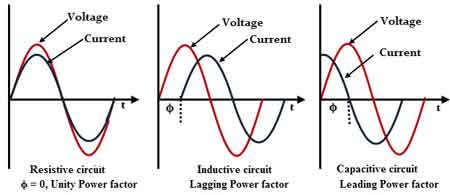
Power factor (PF) determines how much of the apparent electrical demand drawn from a system is converted into useful output.
A high power factor means that most apparent demand becomes productive work. A low PF means a portion circulates reactively, heating conductors, loading transformers, and consuming electrical capacity without delivering useful output.
Download our FREE Electrical Training Catalog and explore a full range of expert-led electrical training courses.

Power factor does not change the apparent power formula. It changes how the result must be interpreted.
Systems that appear lightly loaded when judged only by real output may already be operating near apparent capacity limits. Systems evaluated only by apparent demand, without PF context, may appear inefficient without revealing the underlying cause.
In applied power quality analysis, apparent values must always be interpreted alongside PF to avoid false confidence.
Measured values are commonly validated using tools such as the Apparent Power Calculator when distorted waveforms or non-linear loads are present.
Apparent power describes the total electrical demand placed on a power source by an AC circuit. It combines both real output and reactive circulation into a single value that represents the full electrical burden placed on infrastructure.
Apparent power is measured in volt-amperes (VA) and is calculated using RMS voltage and current:
AP = Voltage × Current
or
S = V × I
Where S is the apparent power in VA, V is the RMS voltage in volts, and I is the RMS current in amperes.
Apparent power is called “apparent” because it does not describe how much useful work the circuit performs. Instead, it represents how much electrical capacity the system must supply to sustain operation.
When low PF increases the apparent power demand, automated correction strategies, such as an automatic PF controller, are often implemented to stabilize system efficiency.
Real power and apparent power describe different aspects of electrical behavior in AC systems.
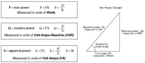
Real power, also called active power, is the portion of electrical energy that performs useful work. It is measured in watts.
Real Power = Voltage × Current × cos φ
or
P = V × I × cos φ
Where P is real output in watts, φ is the phase angle between voltage and current, and cos φ represents the power factor.
Reactive power represents the portion of electrical energy required to sustain electromagnetic fields in inductive and capacitive components.
Reactive Power = Voltage × Current × sin φ
or
Q = V × I × sin φ
Reactive components such as inductors and capacitors store and release energy to maintain electromagnetic fields without producing useful work.
Together, real power, reactive power, and apparent power describe how electrical energy behaves within an AC system.
Apparent power is measured in volt-amperes (VA). This unit reflects total electrical demand rather than usable output. Equipment ratings, transformer sizing, and feeder capacity rely on apparent values because heating and electrical stress follow current rather than real output.
Non-linear and capacitive loads frequently distort the relationship between voltage and current, making the interpretation of apparent power more complex than the formula alone suggests.
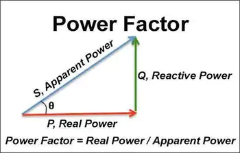
The power triangle illustrates how real power, reactive power, and apparent power relate to one another.
Apparent power forms the hypotenuse of the triangle. Real output forms the horizontal component. Reactive circulation forms the vertical component.
As the power factor approaches one, the apparent demand approaches the real output. As the power factor decreases, apparent demand increases while useful output remains unchanged.
Low power factor, therefore, increases electrical stress without increasing productivity. This results in higher losses, larger conductor requirements, transformer derating, and reduced system efficiency.
Stay informed with our FREE Power Quality Newsletter — get the latest news, breakthrough technologies, and expert insights, delivered straight to your inbox.
Improving power factor reduces apparent demand, lowers losses, and stabilizes overall system behavior.
When waveform distortion complicates this relationship, engineers rely on power quality and harmonics analysis to understand why apparent power trends no longer align with expected thermal behavior.
To calculate apparent power, measure RMS voltage and RMS current using appropriate instrumentation, then multiply them.
RMS measurement accounts for AC waveform behavior and represents the effective heating value of the signal. Once measured, the apparent power formula provides the total electrical demand imposed on the system.
However, the calculation should never be interpreted in isolation. It must be evaluated alongside power factor, waveform distortion, and system loading conditions.
These formulas do not compete with the apparent power formula. They explain its meaning.
Reactive Power Formula
Q = V × I × sin φ
Complex Power Formula
S = P + jQ
Power Factor Formula
PF = P / S
Volt-Amperes Formula
VA = V × I
AC Output Formula
P = V × I × cos φ
Electrical Output Formula
P = V × I
Each formula reveals a different structural aspect of electrical behavior. Together, they prevent engineers from confusing electrical burden with electrical usefulness.
When system performance degrades without obvious overloads, structured power quality troubleshooting often reveals apparent power misinterpretation as the root cause.
The apparent power formula defines electrical stress, not electrical value.
It governs transformer loading, conductor sizing, system margin, and protective design. It does not measure productivity.
Engineers who understand this distinction design systems that operate with margin. Engineers who ignore it design systems that merely appear safe.
Explore 50+ live, expert-led electrical training courses –