Single Phase Transformer Connections Explained
Substation Maintenance Training
Our customized live online or in‑person group training can be delivered to your staff at your location.
- Live Online
- 12 hours Instructor-led
- Group Training Available
Download Our OSHA 3875 Fact Sheet – Electrical PPE for Power Industry Workers
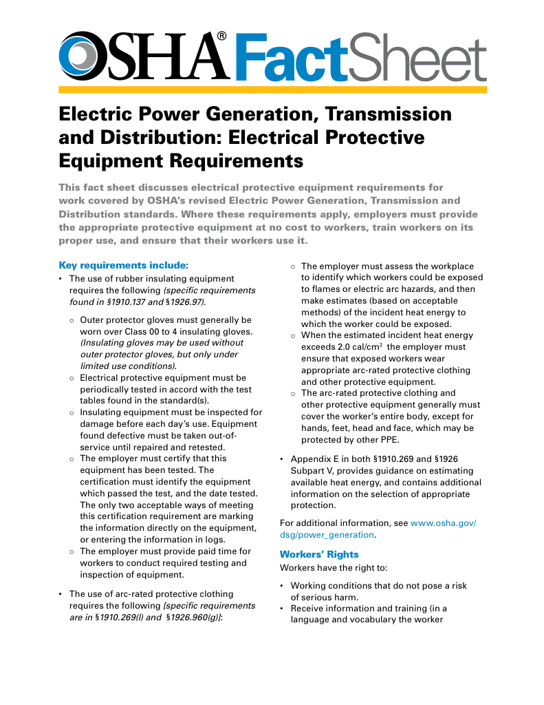
- Follow rules for rubber gloves, arc-rated PPE, and inspection procedures
- Learn employer obligations for testing, certification, and training
- Protect workers from arc flash and electrical shock injuries
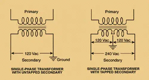
Single phase transformer connections provide efficient voltage transformation in electrical power distribution. They ensure reliable energy transfer, reduced losses, and proper load balance across residential, commercial, and industrial systems.
What are Single Phase Transformer Connections?
Single phase transformer connections are wiring methods used to link primary and secondary windings for effective voltage conversion in power systems.
✅ Enable efficient voltage step-up or step-down
✅ Support balanced residential and commercial loads
✅ Ensure safety and electrical reliability
Electrical Transformer Maintenance Training
Substation Maintenance Training
Request a Free Training Quotation
Single phase transformers, like other electrical devices, may be connected in series or parallel arrangements. For example, distribution transformers are normally wound with the secondary or low-voltage windings that can be connected in series or parallel. The availability of primary voltages and the load requirements dictate how the transformer will be wired. Accurate measurement in transformer banks requires devices such as current transformers to step down the current for metering and protective relays.
Since transformers are essentially AC devices, they do not have a fixed polarity, unlike a DC source. They do, however, have relative polarity markings that must be adhered to when connecting them together in different arrangements. Polarity is the instantaneous voltage obtained from the primary winding in relation to the secondary winding. A control transformer provides stable voltage for control circuits, often working in tandem with single-phase transformer wiring for proper operation.
SIngle phase power transformer leads are generally brought out of the transformer's steel casing through insulating bushings. In all transformers, the H terminals are always the high-voltage terminals, and the X terminals are always the low-voltage terminals. Either can be designated primary or secondary, depending on which is the source and which is the load. By convention, terminals Hi and X1 have the same polarity, which means that when H1 is instantaneously positive, X1 is also instantaneously positive. These markings are used in establishing the proper terminal connections when connecting single-phase transformers in parallel, series, or three-phase configurations. An understanding of polarity is essential for correctly constructing three-phase transformer banks and for properly paralleling single or three-phase transformers with existing electrical systems. Many residential and industrial facilities rely on dry type transformers because they reduce fire risk while supporting parallel or series connections.
Test Your Knowledge About Electrical Transformers!
Think you know Electrical Transformers? Take our quick, interactive quiz and test your knowledge in minutes.
- Instantly see your results and score
- Identify strengths and areas for improvement
- Challenge yourself on real-world electrical topics
Fig. 1. Additive and subtractive transfomer terminal markings
In practice, the terminals on a transformer are mounted in a standard way so that the transformer has either additive or subtractive polarity, as illustrated in Figure 1. A transformer is said to have additive when terminal H1 is diagonally opposite terminal X Similarly, a transformer has subtractive polarity when terminal Hi is adjacent to terminal Xl.
The standard polarity designation for transformers is as follows:
- Transformers manufactured above 200 kVA will have subtractive polarities.
- Transformers with voltage ratings above 9,000 volts, regardless of the kVA rating, will have subtractive polarities.
- Transformers manufactured at or below 200 kVA with a voltage rating of 9,000 volts or less will have additive polarities.
If transformer leads are unmarked, a polarity test can be made to identify and mark the leads. By convention, the top-left terminal when the transformer is looked at from its low voltage side is always labeled H1. In addition to load balancing, specialized devices such as instrument transformers improve system monitoring and fault protection.
Fig. 2. Dual voltage transformer with its secondary windings connected in parallel.
With this in mind, the H1 and H2 leads are labeled. Next, a jumper is connected between the H1 lead and the low-voltage lead adjacent to it, and a voltmeter is connected between H2 and the other low-voltage lead. A low voltage is then applied to the H1 and H2 leads, and the voltmeter reading is recorded. If the voltmeter reading is greater than the applied voltage, the transformer is additive and XI will be the lead on the right. If the voltmeter reading is less than the applied voltage, the transformer is subtractive and Xi is on the left (Figure 2). In this polarity test, the jumper wire effectively connects the secondary voltage ES in series with the primary voltage E. Consequently, ES either adds or subtracts from E. From this, you can see how the terms "additive" and "subtractive" are derived. For galvanic separation and reduced noise disruption, an isolation transformer can be integrated into single-phase transformer systems.
Fig. 3. Two single phase transformers connected in parallel.
Another form of polarity marking is through the use of dots. Dot notation is used with schematic diagrams to express which terminals are positive at the same instant in time. Figure 3 illustrates how dot notation can be used to identify the Hi and Xi leads.
A transformer wiring diagram can be found printed on the transformer nameplate or inside the cover to the wiring compartment. The leads or terminals are marked with 'Hs' and 'Xs'. In general, connecting individual transformers together requires that:
-
Their voltage ratings must be equal.
-
Their percent impedance must be equal.
-
Their polarities must be determined and connections made accordingly.
-
Individual transformers are seldom connected in series. However, if connected in series, their current ratings must be large enough to carry the maximum current of the load. For optimal operation, their current ratings must be equal.
Whether boosting voltage with a step-down transformer or configuring complex delta vs wye arrangements, proper connections ensure safe and efficient power distribution.
Transformers are connected in series to obtain higher voltage ratings and in parallel to obtain higher current ratings. In the example shown in Figure 25-18, the two single-phase transformers are connected with their primaries connected in series. The given parameters of the circuit are a source voltage of 480 volts with two load requirements of 120 volts each. The primary windings are rated at 240 volts and the secondaries at 120 volts. To drop 240 volts across each primary winding, with 480 volts being supplied by the source, the two primary windings are connected in series.
Sign Up for Electricity Forum’s Electrical Transformers Newsletter
Stay informed with our FREE Electrical Transformers Newsletter — get the latest news, breakthrough technologies, and expert insights, delivered straight to your inbox.


