Insulation Resistance Tester For Electrical Maintenance
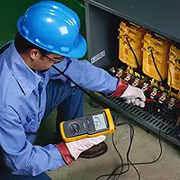
An insulation resistance tester measures the electrical resistance of insulating materials in cables, motors, and equipment. It helps detect insulation breakdown, leakage currents, and moisture intrusion, ensuring electrical safety, equipment longevity, and compliance with industry testing standards.
What is an Insulation Resistance Tester?
An insulation resistance tester is a diagnostic tool used to assess the quality of electrical insulation in systems and components.
✅ Ensures equipment safety by identifying insulation breakdown or degradation
✅ Measures high resistance values in megohms using test voltages
✅ Commonly used in the maintenance of motors, switchgear, and wiring systems
It is a crucial tool in electrical maintenance, used to evaluate the quality of dielectric in various systems. It measures how well the insulation prevents the flow of electrical current, helping to identify potential weaknesses or faults that could lead to equipment failure. Let's explore how these testers work, what features to consider when choosing one, and the safety precautions to follow during testing. Insulation resistance testing is a critical component of a comprehensive electrical testing strategy to verify system reliability and safety.
Frequently Asked Questions
How does an insulation resistance tester work?
It operates by applying a direct current (DC) voltage across the non-conductive layer and measuring the resulting resistance. During the test, a current flows through the insulation material, and the tester measures how much resistance the insulation provides to the flow of electricity. High resistance values indicate a good non-conductive layer, while low resistance values suggest degradation or the presence of moisture. Additionally, the tester can help detect dielectric absorption, which is the ability of the insulation to absorb and release charge over time.
What are the key features to consider?
When selecting a tester, several key features should be evaluated. First, consider the range of test voltages it offers, as different equipment may require varying voltage levels to ensure accurate testing. A wide range of resistance testers can offer voltages from 250V to 5kV or higher, depending on the application. Another important feature is the tester's ability to store and display multiple readings, which is helpful for tracking insulation resistance testing results over time. Additionally, automatic shutoff and overload protection are critical features that enhance both usability and safety.
What types of electrical equipment can be tested?
It can be used on a wide variety of electrical equipment. Motors, transformers, cables, switchgear, and circuit breakers are common examples of equipment tested for quality. Essentially, any component or system that relies on electrical insulation to function safely and effectively can benefit from measuring resistance tests. Regular testing of such equipment can help prevent unplanned outages and equipment failures by identifying insulation issues before they lead to larger problems. When testing motors and rotating equipment, it’s helpful to combine resistance readings with Electric Motor Testing methods to ensure comprehensive analysis.
How do you interpret the results?
Interpreting test results requires understanding the basic relationship between the measured resistance value and the condition of the insulation. Higher resistance values indicate that the non-conductive layer is in good condition and is providing adequate protection. Lower values may indicate contamination, moisture ingress, or aging of the non-conductive layer. Additionally, repeated tests over time enable trend analysis, allowing for the tracking of gradual changes in insulation performance. The dielectric absorption ratio can also be analyzed to provide a more detailed understanding of how the insulation is performing over extended periods.
What safety precautions should be followed?
Safety is paramount when using a tester. Always ensure that the equipment under test is de-energized and properly grounded before commencing the test. Wear the appropriate personal protective equipment (PPE), such as insulated gloves and safety glasses. The tester should also be handled according to the manufacturer’s guidelines to avoid accidents or damage. Lastly, be mindful of the high voltages involved during the test and ensure that no one else is near the equipment being tested.
How Do You Choose the Right One?
Choosing the right tester can be challenging, especially when you're unsure about the specific model, features, or test voltage required. There are six key factors to take into account when selecting the best tester for your needs:
-
What equipment will be tested?
-
What are the voltage requirements for the test?
-
Where will the tests be performed?
-
What insights can this device provide?
-
What is the technician's level of experience?
-
How important is safety in choosing the tool?
Insights from an Insulation Resistance Test
Insulation resistance testing provides a qualitative assessment of the condition of the conductor and the internal resistive medium of various electrical equipment. To begin the test, a DC voltage is applied to the conductor or equipment. This causes a current to flow from the test device into the conductor, charging the insulation. Initially, this current is referred to as a capacitive charging current, and it can be observed on the tester's display.
Initially, the meter will display a lower resistance value as the resistive medium begins to store charge. As more current flows, the reading will show a lower megohm value, indicating how much charge the insulation is holding. If the insulation quality is good, the reading will stabilize at a higher megohm value as the insulation becomes fully charged.
The next type of current is absorption, or polarization, current, which depends on factors such as contamination. For instance, if moisture is present, the absorption current will be higher, resulting in a lower resistance reading. This current takes longer to build compared to the capacitive charging current, so short testing periods may not fully reveal the presence of contaminants.
Lastly, leakage current flows through degraded non-conductive material and into nearby metal components. This current is typically the focus of an insulation resistance test, but for thorough maintenance and troubleshooting, absorption or polarization current should also be evaluated. Some advanced testers are capable of running tests that consider all currents to provide a more complete analysis.
An insulation resistance tester is a vital tool for evaluating the condition of electrical systems. By applying controlled voltages and measuring the resulting resistance, these testers help detect potential non-conductive material failures before they lead to serious issues. Understanding how to operate the tester, selecting the appropriate model, and interpreting test results are crucial for maintaining reliable electrical systems. Always follow safety protocols to ensure a successful and safe testing process. As part of any effective maintenance plan, What is Preventive Maintenance explains how regular testing can extend the life of your electrical systems.
Related Articles
On-Site Training
Interested in cost effective, professional on-site electrical training?
We can present an Electrical Training Course to your electrical engineering and maintenance staff, on your premises, tailored to your specific equipment and requirements. Click on the link below to request a Free quotation.