Types of Short Circuit Faults in a Power System
By William Conklin, Associate Editor
By William Conklin, Associate Editor
Our customized live online or in‑person group training can be delivered to your staff at your location.

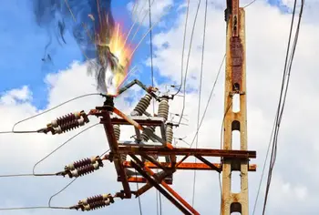
There are four short-circuit faults in power systems: single-line-to-ground, line-to-line, double-line-to-ground, and three-phase faults. They differ in how conductors contact each other or ground, affecting fault current magnitude, system stability, and protection response requirements during operation.
This is the most common short circuit in three-phase power systems. It occurs when one energized conductor unintentionally makes contact with earth, creating a fault path to ground.
This fault occurs when two energized conductors come into direct contact, allowing current to flow between phases without involving ground.
A double line-to-ground fault occurs when two conductors simultaneously come into contact with earth. This type of fault produces higher current levels and more complex system conditions.
This is the least common but most severe fault that occurs when all three conductors come into contact with each other or with earth at the same time. It produces the highest fault currents and places significant stress on the system.
Short Circuit Study & Protective Device Coordination
Arc Flash Analysis/Study - IEEE 1584 Update
In all these different types of short circuit faults in a power system, the path of least resistance is through a fault, and not through the equipment you are attempting to power.
Electrical faults in three-phase power systems can be mainly classified into two types:
Also, these faults can be symmetrical or unsymmetrical.
These faults occur when one or more conductors fail. The figure below illustrates the open-circuit faults for single-, two-, and three-phase (or conductor) open conditions.
The most common causes of these faults include joint failures of cables and overhead lines, failure of one or more phases of the circuit breaker, and melting of a fuse or conductor in one or more phases.
Download our FREE Electrical Training Catalog and explore a full range of expert-led electrical training courses.

Open circuit faults are also called series faults. These are unsymmetrical or unbalanced types of faults, except the three-phase open fault.
Consider that a transmission line is operating with a balanced load before an open-circuit fault occurs. If one of the phase gets melted, the actual loading of the alternator is reduced and this cause to raise the acceleration of the alternator, thereby it runs at a speed slightly greater than synchronous speed. This overspeed causes overvoltages in other transmission lines.
Thus, single- and two-phase open conditions can cause imbalances in power system voltages and currents, resulting in significant damage to equipment.
Broken conductor and malfunctioning of the circuit breaker in one or more phases.
Exceeding the voltages beyond normal values in certain parts of the network, which further leads to insulation failures and the development of short circuit faults.
Although open-circuit faults can be tolerated for longer periods than short-circuit faults, they must be removed as early as possible to minimize the damage.
A short circuit is an abnormal connection of very low impedance between two points of different potential, whether intentional or accidental.
These are the most common and severe types of faults, resulting in abnormally high currents flowing through equipment or transmission lines. If these faults persist for even a short period, they can cause extensive damage to the equipment.
Short circuit faults are also called shunt faults. These faults are caused by insulation failure between phase conductors, between earth and phase conductors, or between both.
The possible short-circuit fault conditions include three-phase to earth, three-phase clear of earth, phase-to-phase, single-phase to earth, two-phase to earth, and phase-to-phase plus single-phase to earth, as shown in the figure.
The three-phase fault clear of earth and the three-phase fault to earth are balanced or symmetrical short circuit faults, while the remaining faults are unsymmetrical.
These may be due to internal or external effects.
Arcing faults can lead to fire and explosion in equipment such as transformers and circuit breakers.
Abnormal currents cause the equipment to overheat, which further reduces the lifespan of its insulation.
The operating voltages of the system can fall below or exceed their acceptance values, causing harmful effects on the service provided by the power system.
The power flow is severely restricted, or even completely blocked, as long as the short-circuit fault persists.
As discussed above, faults are mainly classified into open and short-circuit faults, which can be symmetrical or unsymmetrical.
A symmetrical fault gives rise to symmetrical fault currents that are displaced by 1200 degrees from each other. A symmetrical fault is also called a balanced fault. This fault occurs when all three phases are simultaneously short-circuited.
These faults rarely occur in practice as compared with unsymmetrical faults. Two types of symmetrical faults are line-to-line-to-line (L-L-L) and line-to-line-to-line-to-ground (L-L-L-G), as shown in the figure below.
Think you know Electrical Protection? Take our quick, interactive quiz and test your knowledge in minutes.
A rough occurrence of symmetrical faults is in the range of 2 to 5% of the total system faults. However, if these faults occur, they cause very severe damage to the equipment even though the system remains in a balanced condition.
The analysis of these faults is required to determine the circuit breaker's rupturing capacity and to select set-phase relays and other protective switchgear. These faults are analyzed on a per-phase basis using the bus impedance matrix or Thevenin’s theorem.
The most common faults that occur in the power system network are unsymmetrical faults. This kind of fault gives rise to unsymmetrical fault currents (with unequal magnitudes and unequal phase displacements). These faults are also called unbalanced faults as they cause unbalanced currents in the system.
As discussed above, unsymmetrical faults include both open-circuit faults (single- and two-phase open conditions) and short-circuit faults (excluding L-L-L-G and L-L-L).
The figure below shows the three types of symmetrical faults that occur under short-circuit conditions: phase-to-ground (L-G) fault, phase-to-phase (L-L) fault, and double line-to-ground (L-L-G) fault.
A single line-to-ground (LG) fault is one of the most common faults, and experience shows that 70-80 percent of faults in power systems are of this type. This forms a short circuit path between the line and ground. These are much less severe than other faults.
A line-to-line fault occurs when a live conductor comes into contact with another live conductor. Heavy winds are the major cause of this fault, during which the swinging of overhead conductors may touch together. These are less severe faults, and their occurrence range may be between 15-20%.
In double line to ground faults, two lines come into contact with each other as well as with the ground. These are severe faults, and they occur about 10% of the time compared with total system faults.
Unsymmetrical faults are analyzed using unsymmetrical component methods to determine the voltages and currents throughout the system. The analysis of these faults is more difficult than that of symmetrical faults.
This analysis is necessary to determine the size of a circuit breaker for the maximum short-circuit current. The greater current usually occurs for either the L-G or the L-L fault.
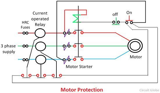
When a fault occurs in any part of the system, it must be cleared quickly to avoid greater damage to equipment and personnel and to prevent power interruptions to customers.
The fault-clearing system uses various protection devices, such as relays and circuit breakers, to detect and clear the fault.
Some of these fault-clearing or fault-limiting devices are given below.
It opens the circuit whenever a fault exists in the system. It consists of a thin copper wire enclosed in a glass or a casing with two metallic contacts. The high fault current raises the wire's temperature, causing it to melt. A fuse necessitates the manual replacement of the wire each time it blows.
It is the most common protection device, capable of making or breaking the circuit, either manually or remotely, under normal operating conditions.
There are several types of circuit breakers available depending on the operating voltage, including air brake, oil, vacuum and SF6 circuit breakers.
These are the fault-detecting devices. These devices detect the fault and initiate the operation of the circuit breaker to isolate the faulty circuit. A relay consists of a magnetic coil and contacts (NC and NO). The fault current energizes the coil, producing a field that operates the contacts.
Some of the types of protective relays include
Magnitude relays
Impedance relays
Directional relays
Pilot relays
Differential relays
Explore 50+ live, expert-led electrical training courses –