Circuit Protection Devices
Circuit Protection Devices
Perhaps the most serious trouble in a circuit is a direct short. The term, “direct short,” describes a situation in which some point in the circuit, where full system voltage is present, comes in direct contact with the ground or return side of the circuit. This establishes a path for current flow that contains no resistance other than that present in the wires carrying the current, and these wires have very little resistance.
Most wires used in aircraft electrical circuits are small gauge, and their current carrying capacity is quite limited. The size of the wires used in any given circuit is determined by the amount of current the wires are expected to carry under normal operating conditions. Any current flow in excess of normal, such as the case of a direct short, would cause a rapid generation of heat. If the excessive current flow caused by the short is left unchecked, the heat in the wire will continue causing perhaps a portion of the wire to melt and at the very least, open the circuit.
To protect aircraft electrical systems from damage and failure caused by excessive current, several kinds of protective devices are installed in the systems. Fuses, circuit breakers, thermal protectors, and arc fault circuit breakers are used for this purpose.
Circuit protective devices, as the name implies, all have a common purpose — to protect the units and the wires in the circuit. Some are designed primarily to protect the wiring and to open the circuit in such a way as to stop the current flow when the current becomes greater than the wires can safely carry. Other devices are designed to protect a unit in the circuit by stopping the current flow to it when the unit becomes excessively warm.
Fuse
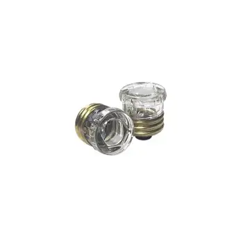
Figure 1 shows the schematic symbol for the fuse. Fuses are used to protect the circuit from over current conditions. The fuse is installed in the circuit so that all the current in the circuit passes through it. In most fuses, the strip of metal is made of an alloy of tin and bismuth, which will melt and open the circuit when the current exceeds the rated capacity of the fuse. For example, if a 5-amp fuse is placed into a circuit, the fuse will allow currents up to 5 amps to pass. Because the fuse is intended to protect the circuit, it is quite important that its capacity match the needs of the circuit in which it is used.
When replacing a fuse, consult the applicable manufacturer’s instructions to be sure a fuse of the correct type and capacity is installed. Fuses are installed in two types of fuse holders in aircraft. “Plug-in holders” or in-line holders are used for small and low capacity fuses. “Clip” type holders are used for heavy high capacity fuses and current limiters.
Fig. 1 - Schematic symbol for fuse.
Current Limiter
The current limiter is very much like the fuse. However, the current limiter link is usually made of copper and will stand a considerable overload for a short period of time. Like the fuse it will open up in an over current condition in heavy current circuits such as 30 amp or greater. These are used primarily to sectionalize an aircraft circuit or bus. Once the limiter is opened, it must be replaced. The schematic symbol for the current limiter is the same as that for the fuse.
Circuit Breaker
The circuit breaker is commonly used in place of a fuse and is designed to break the circuit and stop the current flow when the current exceeds a predetermined value. Unlike the fuse, the circuit breaker can be reset; whereas the fuse or current limiter must be replaced. Figure 10-67 shows the schematic symbol for a circuit breaker.
Fig. 2 - Schematic symbol for circuit breaker
There are several types of circuit breakers in general use in aircraft systems. One is a magnetic type. When excessive current flows in the circuit, it makes an electromagnet strong enough to move a small armature, which trips the breaker. Another type is the thermal overload switch or breaker. This consists of a bimetallic strip which, when it becomes overheated from excessive current, bends away from a catch on the switch lever and permits the switch to trip open.
Most circuit breakers must be reset by hand. If the overload condition still exists, the circuit breaker will trip again to prevent damage to the circuit. At this
point, it is usually not advisable to continue resetting the circuit breaker, but to initiate troubleshooting to determine the cause. Repeated resetting of a circuit breaker can lead to circuit or component damage which trips the breaker. Another type is the thermal overload switch or breaker. This consists of a bimetallic strip which, when it becomes overheated from excessive current, bends away from a catch on the switch lever and permits the switch to trip open.
Arc Fault Circuit Breaker
In recent years, the arc fault circuit breaker has begun to provide an additional layer of protection beyond that of the thermal protection already provided by conventional circuit breakers. The arc fault circuit breaker monitors the circuit for an electrical arcing signature, which can indicate possible wiring faults and unsafe conditions. These conditions can lead to fires or loss of power to critical systems. The arc fault circuit breaker is only beginning to make an appearance in the aircraft industry and is not widely used like the thermal type of circuit breaker.
On-Site Training
Interested in cost effective, professional on-site electrical training?
We can present an Electrical Training Course to your electrical engineering and maintenance staff, on your premises, tailored to your specific equipment and requirements. Click on the link below to request a Free quotation.