The 7 Steps to Complete an Arc Flash Analysis
By Colin P. Hurst, Associate Publisher
By Colin P. Hurst, Associate Publisher
Our customized live online or in‑person group training can be delivered to your staff at your location.

7 Steps to Arc Flash Analysis guide: NFPA 70E and IEEE 1584 compliance, short-circuit and coordination studies, incident energy calculation, PPE selection, arc flash labeling, and mitigation strategies to reduce electrical hazard risk.
What is an Arc Flash Analysis?
An arc flash analysis is an engineered incident energy investigation defined to establish safety protocol for qualified electrical personnel required to work on electrical equipment and circuit parts that cannot be placed in an electrically safe work condition.
Foundational concepts are summarized in the arc flash analysis overview to help teams align terminology and scope.
Protocol such as proper levels of personal protective equipment ppe based on both the shock and arc flash boundaries are defined by the calculated incident energy. Other benefits of an engineered dc arc flash analysis include a short circuit & coordination investigation and updated facility electrical documentation including one-line diagrams and electrical equipment locations.
Request a Free Training Quotation
It is important to understand the process and the “behind the scenes” details of an arc fault analysis. Our other articles describe the importance of an Arc Flash Analysis. In general, the following seven steps are required for the completion of a thorough arc flash study: For context on methodology, consult this arc flash study guide before reviewing the steps.
STEP 1: Acquire existing as-built documentation
The usual starting point for an Arc Flash Analysis is to gather all of the existing electrical drawings that an Owner may have. These would typically include:
If the documentation does not exist, electrical one-lines have to be developed in the field requiring a detailed field survey.
The electrical one-line diagram is the facility electrical distribution road map and is a key part of an Analysis.
A sample electrical one-line diagram
STEP 2: Field verification
Before loading the data from the electrical drawings into the power system software, the drawings must be field verified. This requires a survey of each site to verify one-line documentation and document any missing information in order to generate an encompassing and accurate one-line.
Stay informed with our FREE Arc Flash Newsletter — get the latest news, breakthrough technologies, and expert insights, delivered straight to your inbox.
Understanding how data integrity affects the arc flash hazard analysis ensures measurements are collected with adequate detail.
Equipment covers need to come off so we can visually inspect and acquire PD (protective device) manufacturer/types/sizes/settings, cable type/lengths, transformer impedance values, and KVA sizes. Look below for types of equipment surveyed.
After we gather this information, the covers are then re-installed. De-energizing of equipment is very rare.
STEP 3: Loading Information
After the field survey is complete and the information on the drawings has been verified, this information is then loaded into our software package (SKM Power Tools) to run the Short Circuit, Coordination, and Arc Flash analysis – as shown below.
If you are planning your workflow, review how to complete an arc flash hazard analysis to streamline data entry and validation.
Loading a one-line diagram into SKM looks relative to this:
STEP 4: Run a Short Circuit Analysis
Once the data has been loaded into SKM Power Tools, we review the 3 phase and single line to ground fault currents against the protective device “duty rating” to ensure the device can clear the fault. If a fault occurs at any given protective device, the value of the duty rating is the amount of fault current the device can handle and clear the fault in what we call a “bolted fault”. In other words, if the available fault current is less than the duty rating of the device, the device will do what it is intended and manufactured to do (clear it). If the fault currents are more than the duty rating, the device will likely fail and cause an arc flash incident.
These fault calculations inform an incident energy analysis that directly drives PPE selection and labeling.
STEP 5: Selective coordination
Utilizing the field data and software that performs arc flash calculations, a protection coordination report is then completed. In a properly coordinated system, the nearest protective device upstream of the fault will clear the fault without affecting protective devices further upstream. This will limit the impact of a fault on the overall electrical distribution only to where the fault is located.
In order to be assured that all over current protection devices are coordinated, it is necessary to look at the time vs. current characteristics of each device and compare it to the characteristics of any upstream devices.
It is critical that a facility have proper coordination. Below is an example of “poor coordination” and “improved coordination”.
Poor Coordination
Ideally, where a fault occurs the localized protective device should clear the fault, otherwise, the fault travels back through the system and may trip the building main service device, thus losing power to the entire facility.
Improved Coordination
By making adjustments to the settings of those protective devices that cross over on the time current curve, we are able to clean up the coordination issues. The fault clears at the fault location. Adjustments that we typically make on a protective device (i.e. circuit breaker with these options) include; long time delay, short time pickup, short time delay, and instantaneous.
STEP 6: Arc Flash Evaluation
As part of our report, we evaluate the “as is” condition of the equipment being considered in the investigation. When applicable, we provide recommendations to lower the incident energy levels including maximizing coordination. How we do this and as mentioned in section 5 above, for those protective devices that have the option of making setting adjustments, we can adjust for both; good coordination and lowering of “incident energy levels”. Of course, we look at coordination and arc flash energy “incident energy” hand in hand. Sometimes one does not compliment the other and therefore, we have to review both to maximize the best setting(s) for each.
Download our FREE Electrical Training Catalog and explore a full range of expert-led electrical training courses.

These recommendations should be balanced alongside an arc flash risk assessment that considers task frequency and exposure duration.
STEP 7: System Evaluation
Completing the Arc Flash Analysis includes:
Personnel Protective Equipment (PPE)
Personnel Protective Equipment (PPE) includes clothing and equipment that provide full body protection in the event of an arc flash incident or electrical shock. The protection is based on the NFPA 70E guideline requirement of not receiving more than a second degree burn. A second degree burn is typically non-disabling and curable.
Arc Flash Labels
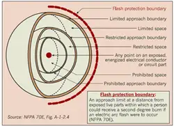
The nominal voltage and arc flash boundary are required on all labels and at least one of the following: available incident energy with the corresponding working distance, minimum arc rating of clothing or specific level of PPE. Generally, we prefer to provide more information than is required on an arc flash label as defined by NFPA 70E. As you can see from our sample label, all the information described is provided. Understanding arc flash boundaries is a critical component of arc flash analysis; learn more on our Arc Flash Boundary page.
Arc Flash Training
Who should have the electrical safety training? The electrical safety training should be provided to any staff who might work on the electrical gear and it is the final step in the Arc Flash Analysis. In many programs, this instruction follows a facility-wide arc flash assessment to ensure content addresses real hazards.
This third entry continues the dialogue describing the importance of performing an arc flash assessment at your facility and the benefits of doing so. I hope this information has been helpful and in my next entry, I will discuss the importance of having your personnel properly trained on the electrical hazards. We call this “Qualified Electrical Safety Training” – another requirement of NFPA 70E.
Explore 50+ live, expert-led electrical training courses –