Hydroelectricity Explained


Hydroelectricity

Hydroelectricity converts hydropower into grid-ready electricity using dams, penstocks, turbines, and generators, enabling renewable baseload, pumped storage, high efficiency, and low emissions for resilient power systems with load balancing, frequency regulation, and strong capacity factors.


What Is Hydroelectricity?

Hydroelectricity is electricity generated by water turning turbines at dams, delivering low-carbon power to the grid.

✅ Converts hydraulic head and flow into alternating current.

✅ Uses synchronous generators, excitation, and step-up transformers.

✅ Supports grid inertia, regulation, and pumped-storage balancing.


Hydroelectricity is another term for power generated by harnessing the power of damming rivers and moving water into generating plants. Not necessarily falling water, just moving water. There are many famous such Hydroelectricity stations in the world, not the least of them at Niagara Falls, Grand Coulee and Boulder Dam and the three gorges dam in China . In the past, small plants produced electric hydroelectricity. Now, they are massive in size and generation capcity as well as having large reservoirs. If there is a need for power electrical generation stations situated close to the point of consumption is ideal. These are just a few of the many examples of energy produced by falling water. On the other hand, a small mill set in the rapids of a fast-moving stream is also an example of it in action, on a lesser scale. The truth is that any steady current of flowing water from a river or other waterway can be converted to power. Of all the sources electricity from hydroelectricity, dammed reservoirs is one of the cleanest possibe ways to generate electricity to a million people, compared with nuclear power. For broader background on water safety and power concepts, the guide on water and electricity explains interactions, risks, and basic generation principles.


How is HydroElectricity Generated?

Hydroelectricity is generated or "manufactured" in large hydroelectric plants, (electrical generating stations) using the same basic principle as a small grist mill yet on a much larger and vastly improved scale for better efficiency, using pumped storage. These power plants contain electrical generators which are attached to massive turbine devices which spin at great speeds as a result of water rushing through them. These pump water power station turbines are much more efficient at extracting the kinetic energy from the moving water and converting that energy it into electrical production through these generators. To see how hydro fits within the wider energy landscape, review how electricity is generated across different prime movers and grid systems.

The amount of electricity from Hydroelectricity extracted from water as an energy source depends not only on the capacities of volume sent through a hydroelectric power plant but on the difference in height between the source and the water's outflow. This height difference is called the head. The amount of potential energy in water is directly proportional to the head and how much water is released. To obtain very high head, water for a hydraulic turbine may be run through a large pipe called a penstock. These relationships between flow, head, and output are core electricity generation principles that guide plant design and optimization.

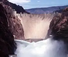
For instance, energy is derived to make electricity water has to move from a higher elevation to a lower elevation through a large tube" otherwise known in technical terms as a "penstock". When the water reaches the end of the penstock, it turns a water wheel or "turbine" at enormous speeds. The turbine rotates, via a connected shaft to an electrical generator, and this generator creates electricity. It is the turbine and generator working in combination that converts "mechanical energy" into "electric energy". The water that makes this possible, is a renewable energy resource, just like the wind that turns the turbine attached to a generator. This mechanical-to-electrical conversion is a classic way to generate electricity efficiently when hydraulic conditions are favorable.

Hydroelectricity may be extracted from water but it depends not only on the volume of water but also on the difference in height between the top of the penstock and where the water spins the turbine. This difference in height is often referred to as the "head". From this "head", it can be determined the exact amount of potential energy that can be converted. Therefore, it is advantageous to build power dams as high as possible to convert the maximum energy from mechanical energy. Project planners evaluate head, flow duration, and dispatch needs in the context of overall electricity production targets and grid reliability.

While many hydroelectricity generating stations supply world power grids, some projects are created for private business purposes. For example, aluminium manufacturing companies require large amounts of power. And there are many other examples of industries that use hydroelectricity in their manufacturing operations. Industrial facilities often diversify procurement among various sources of electricity to balance costs, resilience, and sustainability goals.

While hydroelectricity in the United States seems relatively clean and safe in comparison to burning fossil fuels (coal or oil or natural gas), nearly all large hydroelectricity installations in North America have significant had impacts on nearby environmental habitats once they are brought online. This is because they significantly impede the flow of water in rivers and lakes at the point where the generating dam is installed In turn, this causes significant increases in water levels in corresponding upstream water systems while at the same time creating much lower water levels downstream. Mitigation strategies may include fish passages, adaptive flow management, and complementary alternative electricity options to reduce ecological disruption.

Related News

Harmonic Distortion

Harmonic distortion is the deviation from the ideal electrical waveform caused by nonlinear loads. It impacts power quality, increases heat in equipment, and can lead to system inefficiencies. Monitoring and mitigation are essential in industrial electrical systems.


What is Harmonic Distortion?

Harmonic distortion is not a new phenomenon in power systems. Concern over distortion has fluctuated several times throughout the history of AC electric power systems.

✅ Reduces overall power quality and system reliability

✅ Can damage equipment and increase heat generation

✅ Requires monitoring to ensure system efficiency and safety

In the 1930s and 1940s, the primary sources were transformers, with the primary problem being inductive interference with open-wire telephone systems. Early arc lighting caused similar concern due to its harmonic content, just as today’s electronic power converters do.

Today, nonlinear devices like variable frequency drives (VFDs), arc furnaces, computer power supplies, and LED lighting introduce significant harmonic distortion into electrical systems. Nonlinear devices do not draw current in a linear relationship to voltage, which distorts the sinusoidal waveform and introduces harmonic currents. Harmonic distortion is one of the many issues covered in our comprehensive Power Quality resource channel, which explores causes, effects, and solutions.


Why It Matters

  • Harmonics degrade power quality

  • Increase energy losses and heat in conductors and transformers

  • Lead to premature failure of motors and sensitive electronics

  • Interfere with communication lines

In contrast, voltage sags and interruptions are nearly universal to every feeder and represent the most numerous and significant power quality deviations. The end-user sector suffers more from harmonic problems than the utility sector. Industrial users with adjustable speed drives, arc furnaces, induction furnaces, and similar equipment are significantly more susceptible to problems caused by harmonic distortion. To understand the relationship between harmonics and apparent energy flow, see our explanation of Apparent Power vs Real Power.

A good assumption for most utilities in the United States is that the sine wave voltage generated in central power stations is very good. In most areas, the voltage found on transmission systems typically has much less than 1% distortion. However, the distortion increases as the load approaches. At some loads, the current waveforms barely resemble a sine wave. Electronic power converters can chop the current into seemingly arbitrary waveforms. Managing nonlinear loads often requires Power Factor Correction to reduce harmonic effects and improve efficiency.


Industry Standards

  • IEEE 519: Sets recommended harmonic limits for both voltage and current.

  • IEC 61000-4-7: Defines methods of measuring harmonics and interharmonics.


Harmonic Distortion and Nonlinear Devices

Harmonic distortion is caused by nonlinear devices in the power system. A nonlinear device is one in which the current is not proportional to the applied voltage. Figure 1 illustrates this concept using the case of a sinusoidal voltage applied to a simple nonlinear resistor, where the voltage and current vary according to the curve shown. While the applied voltage is perfectly sinusoidal, the resulting current is distorted. Increasing the voltage by a few percent may cause the current to double and exhibit a different waveform. You can calculate your system’s power quality impact using our Apparent Power Calculator for precise performance metrics.

This is the source of most harmonic distortion in a power system. Figure 1 illustrates that any periodic, distorted waveform can be expressed as a sum of sinusoids. When a waveform is ideal from one cycle to the next, it can be represented as a sum of pure sine waves in which the frequency of each sinusoid is an integer multiple of the fundamental frequency of the distorted wave. This multiple is called a harmonic of the fundamental, hence the name of this subject matter. The sum of sinusoids is referred to as a Fourier series, named after the great mathematician who discovered the concept. Nonlinear loads like VFDs and arc furnaces can affect grounding; learn more in our guide to Electrical Grounding.


Fig. 1. Current distortion caused by nonlinear resistance


Voltage and Current Distortion

The term "harmonics" is often used by itself without further qualification. Generally, it could mean one of the following three:

  1. The harmonic voltages are too great (the voltage is too distorted) for the control to properly determine firing angles.

  2. The harmonic currents are too great for the capacity of some devices in the power supply system, such as transformers, and the machine must be operated at a lower than rated power.

  3. The harmonic voltages are too great because the harmonic currents produced by the device are too great for the given system condition.

Clearly, there are separate causes and effects for voltages and currents, as well as some relationship between them. Thus, the term harmonics by itself is inadequate to describe a problem definitively. Nonlinear loads appear to be sources of harmonic current, injecting harmonic currents into the power system. For nearly all analyses, it is sufficient to treat these harmonic-producing loads simply as current sources. There are exceptions to this as described later.


Fig 2. Harmonic currents flowing through the system impedance result in harmonic voltages at the load.

Voltage distortion is the result of distorted currents passing through the linear, series impedance of the power delivery system, as illustrated in Fig. 2. Although assuming that the source bus is ultimately a pure sinusoid, there is a nonlinear load that draws a distorted current. The harmonic currents passing through the system's impedance cause a voltage drop for each harmonic. This results in voltage harmonics appearing at the load bus. The amount of voltage distortion depends on the impedance and the current. Assuming the load bus distortion stays within reasonable limits (e.g., less than 5%), the amount of harmonic current produced by the load is generally constant.

While the load current harmonics ultimately cause voltage distortion, it is worth noting that the load has no control over the voltage distortion. The same load put in two different locations on the power system will result in two different voltage distortion values. Recognition of this fact is the basis for the division of responsibilities for harmonic control that is found in standards such as IEEE Std 519-1992.

  • Control over the amount of harmonic current injected into the system occurs at the end-use application.

  • Assuming the harmonic current injection is within reasonable limits, the control over voltage distortion is exercised by the entity that controls the system impedance, typically the utility.

One must be careful when describing harmonic distortion phenomena, as there are distinct differences between the causes and effects of harmonic voltages and currents. The use of the term harmonics should be qualified accordingly. By popular convention in the power industry, the term is used by itself most of the time when referring to load apparatus, indicating that the speaker is referring to the harmonic currents. When referring to the utility system, the voltages are generally the subject. For systems affected by harmonic-induced overheating, understanding Capacitor Bank applications is essential for voltage support and harmonic filtering. For in-depth harmonic analysis, explore our guide to using a Power Quality Analyzer to identify waveform distortion and power anomalies.


Related Articles


View more

Electricity Meter

An electricity meter measures electrical energy consumption in homes, businesses, and industries. Also called a power meter or energy meter, it records kilowatt-hours, supports billing, monitors usage patterns, and ensures accurate tracking of electrical load.


What is an Electricity Meter?

An electricity meter is a vital device that utility companies use to measure the amount of electric power consumed by a household or business.

✅ Tracks consumption in kilowatt-hours (kWh) for accurate billing

✅ Monitors load, efficiency, and usage trends over time

✅ Essential for power distribution, energy management, and safety


It provides valuable data that helps both consumers and utility companies monitor power consumption, leading to improved energy management and more accurate billing.


How does an electricity meter work?

It measures the amount of power a household or business consumes, typically in kilowatt-hours (kWh). It records usage over time, allowing utility companies to bill customers accordingly.

Various types exist to suit different applications. The most common include:

  • Electromechanical meters (kWh) with a rotating aluminum disc that measures energy flow.

  • Digital meters that display consumption on an electronic screen.

  • Smart meters are advanced digital devices that automatically transmit usage data to the utility.

Smart meters are central to the smart grid, a modernized system designed to improve the efficiency and reliability of power distribution. With a smart device, consumers can access real-time information about their usage while utilities can implement time-of-use billing to encourage energy conservation during peak hours.


Net Metering & Solar Export Meters

For households with solar panels or other distributed energy sources, net recorders facilitate two-way power flow. They measure both the electrical energy consumed from the grid and the power exported back to it. This enables net metering programs, allowing consumers to earn credits or payments for surplus energy, making the adoption of renewable energy more cost-effective.


Communication & Technology Behind Smart Meters

Smart meters are part of the Advanced Metering Infrastructure (AMI), which utilizes communication networks, including RF mesh, cellular, and power line communication (PLC), to securely transmit usage data to the utility. This connectivity enables demand response programs, remote disconnections, and predictive maintenance, while providing consumers with detailed insights via apps and dashboards.


How do I read my Electricity Meter?

Reading your device may seem complicated, but it’s straightforward:

  • Electromechanical types use dials. Read each from left to right, taking the lower number if the pointer is between two digits.

  • Digital types display readings directly on an LCD screen, often cycling through consumption, demand, and tariff data.
    Some utilities also offer web portals or mobile apps that allow consumers to track their daily or hourly usage.


How can I check if my Electricity Meter is accurate?

To test accuracy, turn off all appliances and observe whether the recorder continues to record consumption. If it does, contact your utility for a professional inspection. Most utilities are required by regulation to maintain meter accuracy within specific tolerances defined by ANSI or IEC standards.

One innovation is the prepaid electricity meter, where consumers pay in advance for power. Once the credit is exhausted, the supply is disconnected until it is recharged. This approach enables households to budget more effectively and promotes conscious energy use.


Security & Privacy in Modern Meters

Electricity meter tampering is a significant concern for utilities. Attempts to reduce recorded consumption can lead to safety hazards and financial losses. Modern recorders include anti-tamper seals, encrypted communication, and intrusion detection to protect data integrity and ensure accurate billing. Utilities also conduct regular inspections to detect and prevent fraud.


What is a Smart Electricity Meter, and how does it differ?

It is a digital device that provides real-time usage data, supports two-way communication, and integrates with the smart grid. Unlike traditional recorders, it enables:

  • Automated reading

  • Dynamic tariffs and demand response

  • Access to consumer dashboards, apps, and alerts

These capabilities enhance billing accuracy, empower consumers to lower their energy costs, and facilitate a more flexible and sustainable grid.


Market Adoption & Trends

Smart meter adoption is growing worldwide. According to industry reports, over 1 billion smart meters have been deployed globally, with continued growth expected in North America, Europe, and Asia. In Canada, utilities like BC Hydro have rolled out smart meters to millions of customers, aiming for more reliable service and reduced outages.


Pros, Cons, and Challenges

Electricity meters offer several clear benefits, including accurate billing, improved energy management, integration with renewable energy sources, and reduced costs associated with manual meter reading. However, challenges include upfront costs, connectivity issues, consumer privacy concerns, and potential inaccuracies if meters drift out of calibration. Addressing these ensures the technology continues to deliver long-term benefits.


The Role of Electricity Meters in Energy Management

Understanding how they work, how to read them, and the different types available helps consumers make informed decisions about their energy usage. By verifying accuracy, adopting advanced technologies such as smart and prepaid meters, and utilizing apps and dashboards, households and businesses can gain greater control over their energy costs.

Ultimately, electricity meters are not just billing devices—they are gateways to improved efficiency, consumer empowerment, and a sustainable energy future.


Frequently Asked Questions


Can I read my smart meter remotely?

Yes. Most enable consumers to view their data via apps or online dashboards provided by their utilities.


How accurate are they?

They must comply with standards like ANSI C12 or IEC 62053, ensuring accuracy within strict tolerances.


What happens if it fails?

If it malfunctions, utilities are legally required to replace it and may use historical usage patterns for interim billing.


Related Articles


View more

Thevenin's Theorem

Thevenin’s Theorem simplifies complex linear circuits into a single voltage source and series resistance, making circuit analysis easier for engineers. It helps calculate current, load behavior, and equivalent resistance in practical electrical systems.


What is Thevenin’s Theorem?

Thevenin’s Theorem is a method in circuit analysis that reduces any linear electrical network to an equivalent circuit with a voltage source (Vth) in series with a resistance (Rth).

✅ Simplifies circuit analysis for engineers and students

✅ Calculates load current and voltage with accuracy

✅ Models equivalent resistance for real-world applications

Thevenin’s Theorem allows any linear, two-terminal circuit to be represented by a single voltage source in series with a resistance.

  • Reduces complex circuits to a simple equivalent consisting of a voltage source and a resistor

  • Makes analyzing load response and network behavior straightforward, saving time and effort

  • Widely used for calculating current, voltage, or power across loads in electrical networks

To fully grasp why Thevenin’s Theorem matters, it helps to revisit the principles of basic electricity, where voltage, current, and resistance form the foundation of all circuit analysis.


Understanding Thevenin’s Theorem

Thevenin’s Theorem is a cornerstone of basic electrical engineering and circuit analysis. First introduced by French engineer Léon Charles Thévenin in the late 19th century, the theorem allows engineers and students alike to simplify a complex electrical network to a single voltage source (known as the Thevenin voltage, Vth) in series with a single resistor (known as the Thevenin resistance, Rth). This is particularly useful when analyzing how a circuit will behave when connected to different loads. Concepts such as Ohm’s Law and electrical resistance work in conjunction with Thevenin’s method, ensuring accurate load and network calculations.

Thevenin’s Theorem states that any linear electrical network can be simplified to an equivalent circuit consisting of a single voltage source in series with a resistance. By removing the load resistance, engineers can calculate the equivalent circuit voltage at the terminals, which represents how the circuit will behave when reconnected. This approach replaces multiple components and ideal voltage sources with one simplified model, making circuit analysis more efficient while preserving accuracy in predicting load behavior.


How Thevenin’s Theorem Works

According to Thevenin’s Theorem, no matter how complicated a linear circuit may be, with multiple sources and resistors, it can be replaced by an equivalent Thevenin circuit. This greatly simplifies the process when you’re only interested in the voltage, current, or power delivered to a specific part of the circuit. The steps typically followed when using Thevenin’s Theorem are:

  1. Identify the portion of the circuit for which you want to find the Thevenin equivalent (usually across two terminals where a load is or will be connected).

  2. Remove the load resistor and determine the open-circuit voltage across the terminals. This voltage is the Thevenin voltage (Vth).

  3. Calculate the Thevenin resistance (Rth) by deactivating all independent voltage sources (replace them with short circuits) and current sources (replace them with open circuits), then determining the resistance viewed from the terminals.

  4. Redraw the circuit as a single voltage source Vth in series with resistance Rth, with the load resistor reconnected.


Why Use Thevenin’s Theorem?

There are several reasons why Thevenin’s Theorem is so widely used in both academic and practical electrical engineering:

  • Simplification – Instead of solving a complex network repeatedly each time the load changes, engineers can just reconnect different loads to the Thevenin equivalent, saving time and reducing the potential for error.

  • Insight – By reducing a circuit to its essential characteristics, it’s easier to understand how changes will affect load voltage, current, or power.

  • Foundation for Further Analysis – Thevenin’s Theorem forms the basis for other network analysis techniques, such as Norton's Theorem, and is fundamental to understanding more advanced topics like maximum power transfer.


Example Application

Imagine a scenario where you need to analyze a circuit with multiple resistors and voltage sources connected in series, with a load resistor at the end. Without Thevenin’s Theorem, calculating the voltage across or current through the load each time you change its resistance would require solving complicated sets of equations. Thevenin’s Theorem allows you to do all the hard work once, finding Vth and Rth, and then quickly see how the load responds to different values.

Illustrative Case: A power supply circuit needs to be tested for its response to varying loads. Instead of recalculating the entire network for each load, the Thevenin equivalent makes these calculations swift and efficient. A deeper look at capacitance and inductance shows how energy storage elements influence circuit behavior when simplified through equivalent models.


Limitations and Conditions

While powerful, Thevenin’s Theorem has limitations:

  • It only applies to linear circuits, those with resistors, sources, and linear dependent sources.

  • It cannot directly simplify circuits containing nonlinear elements such as diodes or transistors in their nonlinear regions.

  • The theorem is most useful for “two-terminal” or “port” analysis; it doesn’t help as much with multiple output terminals simultaneously, though extensions exist.


Connections to Broader Electrical Concepts

Thevenin’s Theorem is closely related to other concepts, such as Norton’s Theorem, which prescribes an equivalent current source and parallel resistance. Both theorems are widely applied in real-world scenarios, including power distribution, signal analysis, and the design of electronic circuits. For example, it's relevant when considering how hydro rates impact load distribution in utility networks.

Thevenin’s Theorem is more than just a trick for simplifying homework—it is a core analytical tool that forms the backbone of practical circuit analysis. Whether you are a student learning circuit theory or an engineer designing power systems, understanding and applying Thevenin’s Theorem is essential.  Understanding current flow and the role of a conductor of electricity provides practical insight into why reducing networks to simple equivalents makes engineering analysis more efficient.


Related Articles


View more

Water Electricity

Water electricity refers to electrical power generated using water, primarily through hydroelectric systems. It converts the kinetic energy of moving or falling water into electricity, providing a renewable and sustainable energy source with low carbon emissions and high efficiency.


What is: “Water Electricity?”

Water electricity, also known as hydroelectric power, is energy derived from moving water. It’s a leading source of renewable electricity worldwide.

✅ Converts water’s kinetic energy into usable electricity

✅ Offers renewable, low-emission electricity generation

✅ Used in dams, rivers, and tidal energy systems

 Most hydroelectric power is generated from the potential energy of dammed water, which drives a water turbine and generator. Less common variations utilize water's kinetic energy or undammed sources, such as tidal power. Hydroelectricity is a renewable energy source.

The energy extracted from water depends not only on the volume but on the difference in height between the source and the water's outflow. This height difference is referred to as the head. The amount of potential energy in water is directly proportional to the head. To obtain a very high head of water for a hydraulic turbine, water may be run through a large pipe called a penstock.

While many supply public power networks, some Water Electricity projects were created for private commercial purposes. For example, aluminum processing requires substantial amounts of power, and in Britain's Scottish Highlands, there are examples at Kinlochleven and Lochaber, designed and constructed during the early 20th century. Similarly, the 'van Blommestein' lake, dam and power station were constructed in Suriname to provide power for the Alcoa aluminum industry. In many parts of Canada (specifically, the provinces of British Columbia, Manitoba, Ontario, Quebec, and Newfoundland and Labrador), hydroelectricity is used so extensively that the word "hydro" is often used to refer to any power delivered by a power utility. The government-run power utilities in these provinces are called BC Hydro, Manitoba Hydro, Hydro One (formerly "Ontario Hydro"), Hydro-Québec and Newfoundland and Labrador Hydro, respectively. Hydro-Québec is the world's largest hydroelectric generating company, with a total installed capacity (2005) of 31,512 MW. For deeper insight into how to generate electricity from various sources, including water, visit our guide on hydroelectricity, which explains methods, systems, and real-world examples.


Importance

Water and Electricity power supplies 20% of the world's electricity. Norway produces virtually all of its energy from hydroelectric sources. In contrast, Iceland produces 83% of its requirements (as of 2004), and Austria generates 67% of all power in the country from hydroelectric sources (over 70% of its total requirements). Canada is the world's largest producer of Water Electricity, and produces over 70% of its electric power from hydroelectric sources.

Apart from a few countries with an abundance of it, hydro capacity is normally applied to peak-load demand, because it can be readily stored during off-peak hours (in fact, pumped-storage hydroelectric reservoirs are sometimes used to store power produced by thermal plants for use during peak hours). It is not a major option for the future in developed countries because most major sites in these countries that have the potential for harnessing gravity in this way are either already being exploited or are unavailable for other reasons, such as environmental considerations.

Regions where thermal plants provide the dominant supply of power utilize Water Electricity to provide the important functions of load following and regulation. This permits thermal plants to be operated closer to thermodynamically optimal points rather than varied continuously, which reduces efficiency and potentially increases pollutant emissions. Concurrently, hydro plants are then utilized to provide for hour-to-hour adjustments and to respond to changes in system frequency and voltage (regulation), with no additional economic or environmental effect.


Related Articles


View more

Types of Electricity - Static and Current

Types of electricity include static electricity and current electricity, which flows as direct current (DC) or alternating current (AC). Electricity can be generated from various sources, including solar, wind, and hydro, but all supply either static or current electricity.


What are the Types of Electricity?

There are two types of electricity: Static Electricity and Current Electricity.

Static electricity results from the buildup of electric charges.

✅ Current electricity includes alternating (AC) and direct (DC) flow.

Static Electricity is made by rubbing together two or more objects, creating friction, while Current electricity is the flow of electric charge across an electrical field.


Static Electricity

Static electricity is when electrical charges build up on the surface of a material. It is usually caused by rubbing materials together. The result of a build-up of static electricity is that objects may be attracted to each other or may even cause a spark to jump from one to the other. For Example, rub a balloon on a wool and hold it up to the wall.

Before rubbing, like all materials, the balloons and the wool sweater have a neutral charge. This is because they each have an equal number of positively charged subatomic particles (protons) and negatively charged subatomic particles (electrons). When you rub the balloon with the wool sweater, electrons are transferred from the wool to the rubber because of differences in the attraction of the two materials for electrons. The balloon becomes negatively charged because it gains electrons from the wool, and the wool becomes positively charged because it loses electrons.


Current Electricity

Current is the rate of flow of electrons. The movement of electrons produces it, and it is measured in amperes. Unlike static electricity, current electricity must flow through a conductor, usually copper wire. Electricity is similar to the flow of water in a river. The river flows from one spot to another, and the speed of the current determines the speed at which it moves. With electricity, current is a measure of the amount of energy transferred over a period of time. That energy is referred to as an electron flow. One of the results of the current is the heating of the conductor. When an electric stove heats up, it's because of the flow of current.

There are various sources of current electricity, including the chemical reactions that occur in a battery. The most common source is the generator. A simple generator produces electricity when a coil of copper turns inside a magnetic field. In a power plant, electromagnets spinning inside many coils of copper wire generate vast quantities of electricity.

There are two main kinds of electric current. Direct (DC) and Alternating (AC). It's easy to remember. Direct current is similar to the energy you obtain from a battery. Alternating current is like the plugs in the wall. The big difference between the two is that DC is a flow of energy, while AC can turn on and off. AC reverses the direction of the electrons.


Related Articles


View more

Basic Electricity – Understanding Current, Voltage, Resistance, and Power

Basic electricity refers to the fundamental concepts of electric charge, current, voltage, and resistance. It explains how electric circuits work, how energy flows, and how components like wires, batteries, and switches interact in homes, schools, and industries.


What is Basic Electricity?

Basic electricity refers to the foundational principles that explain how electric energy is generated, transmitted, and used in circuits. When an electric current flows through a conductor, it creates a magnetic field (or “flux”) around it.

✅ Explains current, voltage, resistance, and power in simple terms

✅ Describes how electric circuits operate and transfer energy

✅ Essential for understanding household wiring, batteries, and switches

Understanding the fundamentals of voltage is essential for grasping how electric circuits function — see our full explanation of voltage.

The strength of this magnetic field increases when the conductor is shaped into a coil with multiple turns. In electrical engineering, this coiled conductor is known as an inductor. If a steady direct current (DC) flows through the coil, it forms an electromagnet—an object with magnetic properties that can be switched on and off using a basic electrical switch.


Basic Electrical Theory

There are four basic electrical quantities that we need to know:

  • Current

  • Potential Difference (Voltage)

  • Power

  • Resistance


Electrical Current

Current is the movement of electric charge through a conductor. Each electron carries a charge of 1.6 × 10⁻¹⁹ coulombs—too small to measure individually—so we measure charge in groups called coulombs. When 1 coulomb of charge passes through a point in a circuit per second, the current is  1 ampere (A). Electric current is measured in amperes and is essential to the functioning of all electrical systems. Learn how voltage drop affects electrical performance and safety in residential and industrial systems. You can estimate losses in long-distance wiring with our easy-to-use voltage drop calculator. For step-by-step guidance on circuit loss calculations, explore the voltage drop formula explained clearly.


Potential Difference

Voltage, or potential difference, refers to the energy per unit charge in a circuit. It represents the work each charge can perform. Think of voltage as the electrical pressure that pushes electrons through a conductor. Higher voltage means more potential energy available to do work, such as lighting a bulb or powering a motor.


Power in a Circuit

Electrical power is the rate at which energy is used or transferred in a circuit. It can be calculated using the formula:

Power (W) = Voltage (V) × Current (A)

This equation is fundamental in both residential and industrial applications, from estimating energy usage to designing electrical systems.


Electrical Resistant Behaviour

Resistance is the opposition to the flow of electric current. It determines how much current will flow for a given voltage. Materials like copper have low resistance and conduct electricity well, while materials like rubber have high resistance and are used as insulators. Learn how voltage drop affects electrical performance and safety in residential and industrial systems.


Electromagnetic Induction

There’s a reciprocal relationship between electric current and magnetism. When a magnet is moved past a conductor at a right angle, it induces a voltage in the conductor—a principle known as electromagnetic induction. The polarity of the induced voltage depends on the direction and orientation of the magnetic field.

This effect becomes more noticeable when the conductor is formed into a coil. As the north pole of the magnet passes the coil, voltage is induced, and current flows. When the south pole passes, the induced voltage reverses polarity, and the current changes direction. This principle is the foundation of generator operation. You can estimate losses in long-distance wiring with our easy-to-use voltage drop calculator.


The Generator and the Sine Wave

In an electric generator, coils placed on opposite sides of a rotating magnet generate alternating current (AC). These voltages combine, doubling the output. For example, a 120-volt, 60-Hz generator creates a wave that oscillates from +169.7V to -169.7V.

This wave is called a sine wave because the voltage at any point corresponds to the sine of the magnet’s angle of rotation. The cycle repeats 60 times per second in North America (60 Hz), creating the household AC power we are familiar with. For step-by-step guidance on circuit loss calculations, explore the voltage drop formula explained clearly.


Forms of Electricity: AC and DC

Electricity exists in two major forms:

  • Alternating Current (AC): The direction of current flow alternates regularly. AC electricity is used in power grids because it is easier to transmit over long distances and is compatible with devices such as transformers and capacitors.

  • Direct Current (DC): The current flows steadily in one direction. DC is commonly used inside electronics and battery-powered devices. Unlike AC, the voltage remains constant, making it easy to measure with a DC voltmeter.


AC – Alternating Current

Alternating current is the most common form of electricity used in homes, businesses, and utilities. It alternates direction 50–60 times per second, depending on the region. AC is generated by AC generators and is favored for its ability to change voltage levels easily, making it efficient for transmission over long distances. Sudden dips in power can disrupt equipment — find out what causes voltage sag and how to prevent it.


DC – Direct Current

Direct current flows continuously in one direction. Because its voltage is steady or changes very slowly, it’s easy to measure. It is used in battery-powered systems and internal electronic circuits. Unlike AC, DC cannot be easily stepped up or down in voltage without the use of complex circuitry.

When calculating AC power, engineers use RMS (Root Mean Square) voltage, which gives an effective value comparable to DC. For example, 120V AC RMS is equivalent in power to 120V DC, despite the AC waveform's variations. Discover how water and electricity interact, including safety considerations and risks in common environments.


Transformers and Induction

Transformers, built using coiled wires around iron cores, rely on electromagnetic induction. When AC flows through the primary coil, it creates a changing magnetic field that induces a voltage in the secondary coil. This allows voltage to be stepped up or down for different uses, such as high-voltage transmission or low-voltage device operation.


Atoms, Electrons, and Electric Charge

To fully grasp electricity, it’s essential to understand atomic structure. All matter is made up of atoms, which contain a nucleus of protons (positive) and neutrons (neutral), surrounded by orbiting electrons (negative). The outermost electrons—called valence electrons—can be knocked loose by energy, creating an electric current.

When electrons leave an atom, it becomes positively charged. This movement of charge is the essence of electricity. The ability of atoms to gain or lose electrons determines whether a material is a conductor (like copper) or an insulator (like plastic).


Electrical Charge and Attraction

One universal rule in electricity and magnetism is that like charges repel and opposite charges attract. A positively charged object will attract a negatively charged one. This principle governs everything from how circuits function to how magnetic fields interact with conductors. To understand how energy use is measured over time, read our overview of the watthour meter and its function.


Related Articles


View more

Sign Up for Electricity Forum’s Newsletter

Stay informed with our FREE Newsletter — get the latest news, breakthrough technologies, and expert insights, delivered straight to your inbox.

Electricity Today T&D Magazine Subscribe for FREE

Stay informed with the latest T&D policies and technologies.
  • Timely insights from industry experts
  • Practical solutions T&D engineers
  • Free access to every issue

Live Online & In-person Group Training

Advantages To Instructor-Led Training – Instructor-Led Course, Customized Training, Multiple Locations, Economical, CEU Credits, Course Discounts.

Request For Quotation

Whether you would prefer Live Online or In-Person instruction, our electrical training courses can be tailored to meet your company's specific requirements and delivered to your employees in one location or at various locations.