Basic Electricity – Understanding Current, Voltage, Resistance, and Power

Basic Electricity

Basic electricity refers to the fundamental concepts of electric charge, current, voltage, and resistance. It explains how electric circuits work, how energy flows, and how components like wires, batteries, and switches interact in homes, schools, and industries.


What is Basic Electricity?

Basic electricity refers to the foundational principles that explain how electric energy is generated, transmitted, and used in circuits. When an electric current flows through a conductor, it creates a magnetic field (or “flux”) around it.

✅ Explains current, voltage, resistance, and power in simple terms

✅ Describes how electric circuits operate and transfer energy

✅ Essential for understanding household wiring, batteries, and switches

Understanding the fundamentals of voltage is essential for grasping how electric circuits function — see our full explanation of voltage.

The strength of this magnetic field increases when the conductor is shaped into a coil with multiple turns. In electrical engineering, this coiled conductor is known as an inductor. If a steady direct current (DC) flows through the coil, it forms an electromagnet—an object with magnetic properties that can be switched on and off using a basic electrical switch.


Basic Electrical Theory

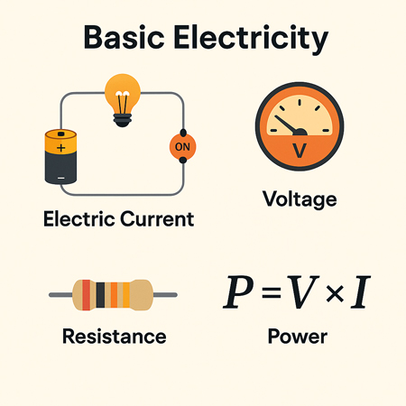
There are four basic electrical quantities that we need to know:

  • Current

  • Potential Difference (Voltage)

  • Power

  • Resistance


Electrical Current

Current is the movement of electric charge through a conductor. Each electron carries a charge of 1.6 × 10⁻¹⁹ coulombs—too small to measure individually—so we measure charge in groups called coulombs. When 1 coulomb of charge passes through a point in a circuit per second, the current is  1 ampere (A). Electric current is measured in amperes and is essential to the functioning of all electrical systems. Learn how voltage drop affects electrical performance and safety in residential and industrial systems. You can estimate losses in long-distance wiring with our easy-to-use voltage drop calculator. For step-by-step guidance on circuit loss calculations, explore the voltage drop formula explained clearly.


Potential Difference

Voltage, or potential difference, refers to the energy per unit charge in a circuit. It represents the work each charge can perform. Think of voltage as the electrical pressure that pushes electrons through a conductor. Higher voltage means more potential energy available to do work, such as lighting a bulb or powering a motor.


Power in a Circuit

Electrical power is the rate at which energy is used or transferred in a circuit. It can be calculated using the formula:

Power (W) = Voltage (V) × Current (A)

This equation is fundamental in both residential and industrial applications, from estimating energy usage to designing electrical systems.


Electrical Resistant Behaviour

Resistance is the opposition to the flow of electric current. It determines how much current will flow for a given voltage. Materials like copper have low resistance and conduct electricity well, while materials like rubber have high resistance and are used as insulators. Learn how voltage drop affects electrical performance and safety in residential and industrial systems.


Electromagnetic Induction

There’s a reciprocal relationship between electric current and magnetism. When a magnet is moved past a conductor at a right angle, it induces a voltage in the conductor—a principle known as electromagnetic induction. The polarity of the induced voltage depends on the direction and orientation of the magnetic field.

This effect becomes more noticeable when the conductor is formed into a coil. As the north pole of the magnet passes the coil, voltage is induced, and current flows. When the south pole passes, the induced voltage reverses polarity, and the current changes direction. This principle is the foundation of generator operation. You can estimate losses in long-distance wiring with our easy-to-use voltage drop calculator.


The Generator and the Sine Wave

In an electric generator, coils placed on opposite sides of a rotating magnet generate alternating current (AC). These voltages combine, doubling the output. For example, a 120-volt, 60-Hz generator creates a wave that oscillates from +169.7V to -169.7V.

This wave is called a sine wave because the voltage at any point corresponds to the sine of the magnet’s angle of rotation. The cycle repeats 60 times per second in North America (60 Hz), creating the household AC power we are familiar with. For step-by-step guidance on circuit loss calculations, explore the voltage drop formula explained clearly.


Forms of Electricity: AC and DC

Electricity exists in two major forms:

  • Alternating Current (AC): The direction of current flow alternates regularly. AC electricity is used in power grids because it is easier to transmit over long distances and is compatible with devices such as transformers and capacitors.

  • Direct Current (DC): The current flows steadily in one direction. DC is commonly used inside electronics and battery-powered devices. Unlike AC, the voltage remains constant, making it easy to measure with a DC voltmeter.


AC – Alternating Current

Alternating current is the most common form of electricity used in homes, businesses, and utilities. It alternates direction 50–60 times per second, depending on the region. AC is generated by AC generators and is favored for its ability to change voltage levels easily, making it efficient for transmission over long distances. Sudden dips in power can disrupt equipment — find out what causes voltage sag and how to prevent it.


DC – Direct Current

Direct current flows continuously in one direction. Because its voltage is steady or changes very slowly, it’s easy to measure. It is used in battery-powered systems and internal electronic circuits. Unlike AC, DC cannot be easily stepped up or down in voltage without the use of complex circuitry.

When calculating AC power, engineers use RMS (Root Mean Square) voltage, which gives an effective value comparable to DC. For example, 120V AC RMS is equivalent in power to 120V DC, despite the AC waveform's variations. Discover how water and electricity interact, including safety considerations and risks in common environments.


Transformers and Induction

Transformers, built using coiled wires around iron cores, rely on electromagnetic induction. When AC flows through the primary coil, it creates a changing magnetic field that induces a voltage in the secondary coil. This allows voltage to be stepped up or down for different uses, such as high-voltage transmission or low-voltage device operation.


Atoms, Electrons, and Electric Charge

To fully grasp electricity, it’s essential to understand atomic structure. All matter is made up of atoms, which contain a nucleus of protons (positive) and neutrons (neutral), surrounded by orbiting electrons (negative). The outermost electrons—called valence electrons—can be knocked loose by energy, creating an electric current.

When electrons leave an atom, it becomes positively charged. This movement of charge is the essence of electricity. The ability of atoms to gain or lose electrons determines whether a material is a conductor (like copper) or an insulator (like plastic).


Electrical Charge and Attraction

One universal rule in electricity and magnetism is that like charges repel and opposite charges attract. A positively charged object will attract a negatively charged one. This principle governs everything from how circuits function to how magnetic fields interact with conductors. To understand how energy use is measured over time, read our overview of the watthour meter and its function.

Related News

Choose The Right Conductor of Electricity

Conductor of electricity describes materials with high electrical conductivity, enabling current flow via free electrons or ions under voltage, such as copper, silver, and aluminum, used in wires, busbars, grounding, and power distribution systems.


What Is a Conductor of Electricity?

A conductor of electricity is a material that easily transmits electric current via free electrons or ions.

✅ Exhibits high conductivity and low resistivity under voltage

✅ Examples: copper, silver, aluminum, graphite, saline water

✅ Enables efficient current flow in cables, busbars, and circuits


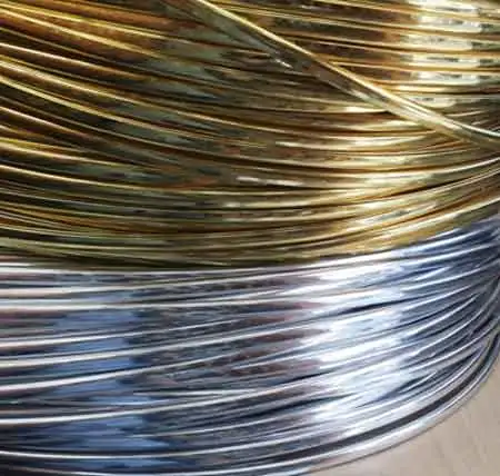
A conductor of electricity is a material that allows electric charges to flow through it with little or no resistance. Copper, aluminum, silver, gold, and nickel are some of the most common conductive materials used in electrical engineering. Conductivity is affected by several factors, such as the material's composition, temperature, and impurities. Conductors are distinguished from insulators, which are materials that do not allow electric charge to flow through them. Electrical resistance measures a material's opposition to the flow of electric current. Understanding the properties of conductive materials is essential in designing and operating electrical circuits that power our world. For foundational context, see this overview of electricity to clarify related terms.

The basic principle of a conductor is that it contains free electrons that are not bound to any particular atom. Conductors allow negatively charged electrons to flow easily in an electric field from one atom to another. When a conductor is connected to a source of electric charges, such as a battery, the electrons in the conductor begin to flow in the direction of the electric field. For newcomers, this introduction to conductors expands on how free electrons move under an applied field.

One of the most widely used conductor of electricity is copper. Copper is an excellent conductor of electrical current due to its high conductivity and low electrical resistance. As a result, copper wires are commonly used to transmit electric power over long distances. Copper is also highly durable, making it ideal for use in applications that require long-term reliability.

Aluminum is another common conductor of electrical current. It is cheaper and lighter than copper, which makes it an attractive option for electrical transmission lines. However, aluminum has a lower conductivity than copper, meaning more aluminum is needed to carry the same electric current as copper. This can lead to increased costs for larger electrical applications.

Silver is the best conductor of electrical current known to man. It has the highest electrical conductivity of any metal and is more conductive than copper. However, silver is much more expensive than copper and is only used in applications where its superior conductivity is required.

Gold is also an excellent conductor of electrical current, but it is even more expensive than silver. As a result, gold is mainly used in high-tech applications, such as electronics and aerospace, where its high conductivity and resistance to corrosion are critical.

Nickel is another metal that is a good conductor of electrical current. As a result, it is commonly used in electrical heating applications, such as in electric ovens and toasters.

A material's conductivity measures how easily it allows electric charge to flow through it. Conductivity is affected by several factors, such as the material's composition, temperature, and impurities. Pure water is an example of a poor conductor of electrical current since it contains very few free electrons.

Conductors are distinguished from insulators, which are materials that do not allow electric charge to flow through them. Rubber and plastic are good insulators that cover wires and cables to prevent electrical shock.

Electrical resistance measures a material's opposition to the flow of electric current. The resistance of a conductor depends on the material's composition, temperature, and length. In addition, Ohm's law states that the current through a conductor between two points is directly proportional to the voltage across the two points. For a deeper dive, this guide to electrical resistance explains the underlying physics and units. You can also review the resistance formula to see how voltage, current, and resistance interrelate in practice.


What are the 3 types of conductors?

Metallic conductors: Metallic conductors are materials made of metal that can conduct power. They contain free electrons not bound to any particular atom and can easily move through the metal lattice. Copper, aluminum, silver, gold, and nickel are some examples of metallic conductors.

Electrolytic conductors: Electrolytic conductors are solutions that can conduct due to the presence of dissolved ions. These solutions are typically made of an electrolyte and a solvent. Examples of electrolytic conductors include solutions of salt, acid, and base.

Semiconductor conductors: Semiconductor conductors are materials that have electrical conductivity between the conductors and insulators. They are used in electronic devices such as transistors, diodes, and solar cells. Some common semiconductor materials include silicon, germanium, and gallium arsenide.


What is the main conductor?
Copper is the most commonly used conductor due to its high electrical conductivity and low electrical resistance. It is also highly durable, making it ideal for use in applications that require long-term reliability. For example, copper wires are commonly used in power distribution systems to transmit electric power over long distances.


What properties does a conductor have?

In addition to high electrical conductivity and low electrical resistance, conductors also have high thermal conductivity, meaning they can transfer heat efficiently. In addition, they have low melting points, allowing them to be easily molded and shaped. Conductors are also ductile, easily drawn into thin wires without breaking.


What makes a good conductor of electricity?

A good conductor of electricity has a high number of free electrons available for conducting an electric charge. It also has low electrical resistance, meaning that it does not impede the flow of electric charge. In general, metals make good conductors of power because they have a high number of free electrons.


How does a conductor conduct electricity?

When a conductor is connected to a source of electric charge, such as a battery, the electric field causes free electrons in the conductor to move in the direction of the field. This movement of free electrons creates an electric current, the flow of electric charge.


What are some examples of good conductors?

Some examples of good conductors include copper, aluminum, silver, gold, and nickel. These metals have many free electrons and low electrical resistance, making them ideal for conducting an electric charge.


What is the difference between a conductor and an insulator?

The main difference between a conductor and an insulator is that a conductor allows an electric charge to flow with little or no resistance. In contrast, an insulator does not allow electric charge to flow. Insulators are typically used to cover or insulate conductors to prevent electric shock or keep the electric charge within a circuit. For a formal definition that complements this comparison, consult a concise conductor definition for precise terminology.


What is the role of a conductor in an electrical circuit?

The role of a conductor in an electrical circuit is to provide a path for the flow of electric charge. In addition, conductors connect the different components of an electrical circuit, such as resistors, capacitors, and inductors. They also transmit electric power from one place to another through power lines. For component selection context, see common types of resistors that conductors connect within practical circuits.


What is the importance of conductivity in electrical systems?

Conductivity is an essential property of materials used in electrical systems because it determines how easily an electric charge can flow through a material. Materials with high conductivity are used in applications where efficient transmission of electric power is required, such as in power distribution systems. Conversely, materials with low conductivity are used as insulators to prevent the flow of electric charge.


How does the thickness of a conductor affect its ability to conduct?

The thickness of a conductor affects its ability to conduct electrical current because thicker conductors have a lower electrical resistance. This means thicker conductors can carry more electric current with less power loss due to resistance. For example, a thin copper wire may not be able to have as much current as a thicker copper wire of the same length due to the increased resistance of the thinner wire. Therefore, the thickness of a conductor is an essential consideration in designing electrical circuits, especially for high-current applications where minimizing power loss due to resistance is critical. Additionally, thicker conductors are more durable and less likely to break under stress, making them more suitable for applications where mechanical stress is present, such as bridges and buildings.
  If these tradeoffs are new to you, this primer on electrical resistance connects cross-sectional area to current flow with clear examples.


Related Articles

View more

Windmills For Electricity Explained

Windmills for electricity use wind energy to generate clean, renewable power. These wind turbines convert kinetic energy into electrical energy, reducing carbon emissions and dependence on fossil fuels. 


What are Windmills for Electricity?

Windmills for electricity are modern devices that transform kinetic wind energy into electrical power.

✅ Harness renewable energy for clean power

✅ Reduce carbon footprint and dependence on fossil fuels

✅ Support sustainable power generation worldwide

Windmills for electricity are part of a broader shift toward renewable energy, providing clean alternatives to fossil fuels for homes, businesses, and utilities.


History of Windmills

Windmills for electricity - Mankind has been harnessing the wind's energy for many years. From Holland to traditional farms around the world, windmills were used in the past for pumping water through primitive irrigation systems or to grind grain. Then, the wind turned large "sails" that were connected by a long vertical shaft, which was attached to a grinding machine or a wheel that turned and drew water from a well. Today's turbines harness the energy of the wind to turn large metal blades, which in turn spin a generator that produces electric power. Alongside wind, other renewable energy sources like solar, biomass, and tidal energy are shaping a diversified and sustainable energy future.

From the mid-1970s to the mid-1980s, the United States government collaborated with industry to advance windmill technology for power generation and enable the development of large commercial wind turbines. NASA led this effort at the Lewis Research Center in Cleveland, Ohio, and it was an extraordinarily successful government research and development activity.


National Science Foundation

With funding from the National Science Foundation and later the Department of Energy (DOE), a total of 13 experimental wind turbines were put into operation, including four major wind turbine designs. This research and development program pioneered many of the multi-megawatt turbine technologies in use today, including steel tube towers, variable-speed generators, composite blade materials, partial-span pitch control, as well as aerodynamic, structural, and acoustic engineering design capabilities. The large Windmills For Electricity developed under this effort set several world records for diameter and power output. The Mod-2 wind turbine cluster produced a total of 7.5 megawatts of power in 1981. Government incentives, such as alternative energy tax credits, have played a major role in expanding wind power adoption across North America.


Wind Turbine Technology

In 1987, the Mod-5B was the largest single wind turbine operating in the world with a rotor diameter of nearly 100 meters and a rated power of 3.2 megawatts. It demonstrated an availability of 95 percent, an unparalleled level for a new first-unit wind turbine. The Mod-5B featured the first large-scale variable-speed drive train and a sectioned, two-blade rotor, which enabled easy transport of the blades.

Later, in the 1980s, California provided tax rebates for ecologically harmless wind turbines. These rebates helped fund the first major deployment of wind power for the utility grid. These turbines gathered in large wind parks such as at Altamont Pass, would be considered small and uneconomical by modern wind power development standards.

In the 1990s, as aesthetics and durability became more important, turbines were placed atop steel or reinforced concrete towers. Small generators are connected to the ground tower, and then the tower is raised into position. Larger generators are hoisted into position atop the tower, and a ladder or staircase is located inside the tower to allow technicians to reach and maintain the generator.

Originally, wind turbines were built right next to where their power was needed. With the availability of long-distance electric power transmission, wind generators are now often on wind farms in windy locations, and huge ones are being built offshore, sometimes transmitting power back to land using high-voltage submarine cable. Since wind turbines are a renewable means of generating power, they are being widely deployed, but their cost is often subsidized by taxpayers, either directly or through renewable energy credits. Much depends on the cost of alternative energy sources. The cost of wind generators per unit of power has been decreasing by about 4% per year.


Modern Wind Turbines

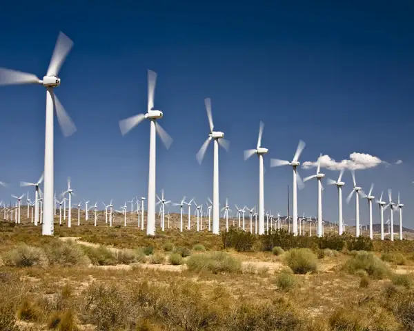
The most modern generations of Windmills for electricity are more properly called wind turbines, or wind generators, and are primarily used to generate electric power. Modern windmills are designed to harness the energy of the wind and convert it into electric energy. The largest wind turbines can generate up to 6 MW of power (for comparison, a modern fossil fuel power plant generates between 500 and 1,300 MW). Many large-scale renewable energy projects now combine wind farms with solar and storage systems, ensuring reliable, clean power for communities worldwide.

Small wind turbines can generate as little as a few kilowatts, while larger models produce up to 100 kilowatts or more, depending on design and location. These devices capture moving air, and as wind turbines operate, the kinetic energy generated can be used directly or sent into the electrical grid. On a utility scale, wind farms combine many large turbines to deliver massive amounts of energy, powering thousands of homes and businesses. This range of applications, from residential to industrial, demonstrates the versatility of wind technology in meeting diverse energy needs.


Related Articles


View more

Electricity Deregulation Explained

Electricity deregulation enables competitive energy markets, retail choice, and wholesale power pricing, separating generation from transmission and distribution to enhance grid reliability, lower tariffs, spur innovation, and diversify suppliers for industrial and commercial loads.


What Is Electricity Deregulation?

Electricity deregulation unbundles utilities, enabling market-based generation, retail choice, and efficient pricing.

✅ Unbundles generation, transmission, and distribution functions.

✅ Enables locational marginal pricing and demand response programs.

✅ Promotes independent system operators and competitive wholesale markets.


In The United States, Electricity Deregulation is now more than 15 years into an experiment to deregulate and restructure the electric power generation, transmission and distribution industry. Some claim that it has produced national benefits as much as $30 billion per year. Others claim the change has resulted in penalties as high as $30 billion per year. And still others point to major declines in reliability and increased frequency of blackouts. For context, resources like what electricity is can clarify foundational terms before policy comparisons.

Why are there such broad disagreement about the impact? How do the results of deregulation and restructuring compare with predictions? Has the change benefited our industrial or commercial users, ordinary consumers and our national economy? To determine the answers to these questions, the key changes that were implemented must be reviewed. A primer on electric power systems helps frame how generation, transmission, and distribution interact under different market rules.

The nature of electric power systems requires significant investments in major facilities, typically costing from tens of millions to billions of dollars. These facilities have long construction lead-times, taking years from start to completion, and often remain in service for as long as 40 years. Regulation provided for the return of the investment (depreciation) and the return on the investment (earnings) over the facilities lifetime. These cost-recovery structures ultimately filter into electricity prices that customers see on their bills.

The systems were interconnected to take advantage of the diversity in times of peak use and in times of equipment failures and emergencies. The industry focus was on long-term cost minimization. Decisions were based on life-cycle cost analyses. In such an environment, a high degree of cooperation developed among those involved in owning, managing, planning and operating electric power systems2. The national savings from this cooperation and interconnection were carefully studied many times and had increased to nearly $20 billion annually3 by the late 1980s. Prices to consumers, controlled by state regulators, were reduced by these savings. Such regional coordination also stabilizes electricity supply during peak seasons and emergencies.

Many supporters of this and the introduction of competition into the electric power business believed it would lead to significant economic benefits and price reductions to consumers. The move to have competition replace government regulation gained many adherents, particularly in large industry, where there were concerns over growing foreign competition; with economists in the nation's universities, who welcomed an opportunity to apply their theories; by investment bankers, who saw the huge fees they would earn to finance numerous buyouts and mergers; by lawyers, accounting organizations and some engineers, who saw increased business; and by entrepreneurs, who saw opportunities for huge profits. Some utility executives believed competition would help increase the return to investors that had, at times, been unfairly limited by regulators. Advocates often cited gains in electricity power market efficiency as proof that liberalization could unlock innovation.

In general, those favouring Electricity Deregulation and competition as a driver were not aware of its effect on the benefits of coordination. Most lacked knowledge of power systems functioning and costs. The concept that profits would increase for the suppliers while prices would go down for consumers obviously required major cost reductions. But no analyses of the source of these cost reductions were conducted by competent engineers. Rather, it was the common belief they would result from increased competition. They sometimes conflated consumer-level tactics like how to save electricity with systemic cost drivers in bulk power operations.

Have such cost reductions occurred? The answer is clearly no. There have been some improvements in generator unit availability and efficiency. On the other hand, there have been huge additional costs and cost increases stemming from the reduced benefits of coordination, the increased complexity of the system, scheduling, and other operating procedures. For end users, focusing on saving electricity can mitigate bill impacts even as market-level costs fluctuate.


Related Articles

View more

Types of Resistors

Types of resistors are essential in electronics, as they control current, reduce voltage, and ensure circuit stability. From fixed and variable resistors to specialized forms like thermistors and photoresistors, each type plays a critical role in electrical engineering.


What are the Various Types of Resistors?

Types of resistors describe categories of electronic components designed to limit current and manage voltage in circuits."
✅ Fixed resistors ensure stable resistance values

✅ Variable resistors adjust resistance as needed

✅ Specialized resistors respond to heat or light


There are two main types of resistors: fixed and variable. Fixed resistors maintain a constant value, while variable resistors can be adjusted to suit changing requirements. Within these groups are many designs crafted from various materials, each selected for its precision, stability, and suitability in specific applications. When studying how different resistor types perform, it helps to review Ohm’s Law Formula, which explains the mathematical relationship between voltage, current, and resistance.

In addition to resistors, other passive components, such as capacitors, are equally important for controlling current flow and stabilizing electrical circuits.


Common Types of Resistors

Type Key Feature Typical Use
Carbon Film Low cost, general use Everyday electronics
Metal Film High accuracy, low noise Precision circuits
Metal Oxide Surge resistant Power supplies
Wire-Wound High power handling Industrial applications
Surface-Mount (SMD) Compact, space-saving Modern circuit boards
Potentiometer Adjustable resistance Volume/tuning controls
Thermistor Temperature-sensitive Sensors, protection devices


Fixed Types of Resistors


Carbon Film Resistors

Carbon film resistors are inexpensive, reliable, and widely used in general-purpose electronics. By applying a thin carbon layer to a ceramic base, they provide a stable resistance for everyday circuits. While not as precise as modern designs, they remain popular where high accuracy isn’t required.


Carbon Composition Resistors

Once the standard in consumer electronics, carbon composition resistors are now less common, but they still serve in circuits that need high pulse load capacity. They offer durability in the face of sudden surges, although their long-term stability and accuracy are lower than those of newer types.


Metal Film Resistors

Metal film resistors, made by depositing a nickel-chromium alloy onto a ceramic substrate, are prized for their precision. With excellent stability, low noise, and tight tolerances, they are widely chosen for high-frequency and sensitive applications. However, they cannot dissipate as much power as wire-wound resistors and are vulnerable to strong surges.


Metal Oxide Resistors

Using oxides like tin or ruthenium on ceramic, metal oxide resistors are known for their robustness. They combine good tolerance with the ability to withstand high voltages, making them ideal where surge protection is essential. While not as accurate as metal film resistors, they offer higher reliability in demanding conditions.


Wire-Wound Resistors

Built from coiled metal wire wrapped around a ceramic or fibreglass core, wire-wound resistors excel in high-power applications. Their ability to handle large currents and high temperatures makes them indispensable in heavy-duty circuits. Their main drawback is bulk, and at high frequencies, their inductance can interfere with performance.


Metal Strip (Foil) Resistors

Metal strip or foil resistors deliver the highest accuracy and stability, with tolerances as fine as 0.005%. Their precision makes them the component of choice in measurement instruments and high-end electronics. Their primary downsides are cost and limited power dissipation, which restrict their use in everyday applications.


Thick and Thin Film Resistors

Produced by different deposition techniques, thick and thin film resistors serve specialized roles. Thick film designs are durable and suited to power electronics and automotive systems, while thin film types offer high accuracy and stability in precision or high-frequency circuits.


Surface-Mount Resistors (SMDs)

Surface-mount resistors are compact components soldered directly onto printed circuit boards. They make modern electronics smaller and more efficient, and although tiny, they cover a wide range of resistance values to support everything from consumer devices to industrial controls.


Variable Types of Resistors

Engineers often use practical examples to compare the unit of electrical resistance with how resistors function in series and parallel arrangements.

Potentiometers

Potentiometers are adjustable resistors that allow manual control over current or voltage. They are common in volume dials, tuning controls, and adjustable circuits where user input is required.


Light-Dependent Resistors (LDRs)

LDRs change resistance with varying light levels, making them useful in light sensors, alarms, and automatic lighting systems.


Thermistors

Thermistors alter resistance with temperature. Positive temperature coefficient (PTC) types increase resistance as they heat, protecting circuits from over-current, while negative temperature coefficient (NTC) types reduce resistance with rising temperature, making them useful for sensing and regulation.

When considering the various types of resistors, they may be simple components, but their diversity makes them essential to every circuit. Whether precision, power handling, or responsiveness to environmental changes is needed, there is a resistor designed for the task. Selecting the right one ensures accuracy, stability, and safety in electronic design.


Related Articles


View more

Electricity Windmill Explained

Electricity windmill converts wind energy into electrical power via rotor blades, generator, gearbox, and inverter, supporting renewable energy, grid integration, power electronics, and efficient electricity production with modern control systems and variable-speed drives.


What Is an Electricity Windmill?

An electricity windmill converts kinetic wind energy into grid-grade electrical power via a wind turbine system.

✅ Generator, gearbox, and rotor optimize energy capture

✅ Inverter and VFD enable grid-quality AC output

✅ SCADA monitors performance, safety, and fault detection


Electricity windmill Mankind been harnessing the wind's energy for many years. From Holland to traditional farms around the world, old style windmills were used in the past for pumping water through primative irrigation systems or used to grind grain. Then, the wind turned large "sails" which were connected by a long vertical shaft that was attached to a grindnig machine or to a wheel that turned and drew water from a well. Today's wind turbine generators can utilize the clean energy of high wind speeds to turn large metal blades which in turn spins a generator that manufactures electric power. For a deeper overview of modern designs, the resource at windmills for electricity explains key configurations used by utilities today.

Electricity windmill turbines, unlike the machines of old, are mounted on very tall towers in order to capture the most wind energy available. At 100 feet (30 meters) or more above ground, wind turbines can take advantage of the faster and less turbulent wind. Turbines catch the wind's energy with their propeller-like blades. Usually, two or three blades are mounted on a shaft to form a rotor. If you're curious how these rotating blades ultimately power homes, see how turbines generate electricity through step-by-step conversion processes.

A blade acts much like an airplane wing. When the wind blows, a pocket of low-pressure air forms on the downwind side of the blade. The low-pressure air pocket then pulls the blade toward it, causing the rotor to turn. This is called lift. The force of the lift is actually much stronger than the wind's force against the front side of the blade, which is called drag. The combination of lift and drag causes the rotor to spin like a propeller, and the turning shaft spins a generator to make power. The rotating shaft must be matched to an electricity generator with appropriate gearing and controls to optimize output.

In recent years, governments have invested enormous amounts of (taxpayer) money in electricity windmill "wind farms" to generate large amounts of energy from large and small wind turbines that take advantage of high winds. These wind systems or energy systems use wind turbine power to create electricity.  Other energy sources like solar power do not produce as much electricity. The only problem with wind generated power is that when the wind stops, so does the generator and therefore the electric power production. Electric power cannot be produced and stored for consumption later. Therefore, wind power can only be counted on mostly when the wind is blowing at optimal speeds and only in locations where the prevailing winds are such that it makes economic sense to build these power plants and this may not be when and where the power is needed. Grid planners track regional electricity production profiles to determine how much wind capacity can be integrated without compromising reliability. As part of a balanced portfolio, policy makers also evaluate alternative electricity options that can complement variable wind resources.

Stand-alone electricity windmill turbines are typically used for water pumping or communications. However, homeowners, farmers, and ranchers in windy areas can also use wind turbines as a way to cut their power bills. For off-grid ranch operations, understanding the interplay between pumps and water electricity systems helps size batteries and controllers correctly.

Small electricity windmill systems also have potential as distributed energy resources. Distributed energy resources refer to a variety of small, modular power-generating technologies that can be combined to improve the operation of the electric power delivery system. In some regions, small-scale hydroelectricity can serve as a firm companion to wind in distributed portfolios.


Related Articles

View more

Electricity Production

Electricity production converts primary energy into power via thermal, hydro, wind, and solar systems, optimizing efficiency, capacity factor, grid stability, transmission reliability, and emissions through turbines, generators, inverters, and advanced SCADA control.


What Is Electricity Production?

Electricity production converts energy to electric power, prioritizing efficiency, safety, and grid reliability.

✅ Conversion via turbines, generators, inverters, and transformers

✅ Control with SCADA, protective relays, and load-frequency regulation

✅ Optimization of efficiency, capacity factor, and emissions


Electricity Production continues to grow around the world, from a variety of energy power sources. In terms of world electricity generation, the US Department of Energy predicts advances strongly from 2004 to 2030. Global production increases by 2.4 percent per year over the projection period, from 16,424 billion kilowatthours in 2004 to 30,364 billion kilowatthours in 2030. Much of the growth in electric power demand is projected for nations outside the OECD. Although the non-OECD nations consumed 26 percent less electricity than the OECD nations in 2004, total generation in the non-OECD region in 2030 is projected to exceed generation in the OECD by 30 per cent. For context, the International Energy Outlook provides a concise overview of electricity generation trends worldwide today.

Total electricity demand in the non-OECD nations is expected to grow from 2004 to 2030 at an annual rate that is nearly triple the rate of growth for electricity demand in the OECD. The difference reflects the relative maturity of electricity infrastructure in the more developed OECD region, as well as the expectation that populations in the OECD countries generally will grow slowly or decline over the next 25 years. In addition, fast-paced growth in the developing non-OECD economies translates to rising standards of living and robust growth in consumer demand for lighting and appliances. Total electricity generation in the non-OECD region increases by an average of 3.5 percent per year in the IEO2007 reference case, as compared with a projected annual growth rate for OECD electricity generation that averages 1.3 per cent per year from 2004 to 2030. Among the energy end-use sectors, the most rapid growth in total world demand for electricity is projected for the buildings (residential and commercial) sectors.

Understanding the diversity of sources of electricity helps explain regional growth patterns in demand.

In Power plants, electricity Production involves the generation or creation of electric power, using rotating turbines attached to an energy generator. This mechanical manufacturing of electricity produces most commercially available electricity. Turbines are driven by a fluid which acts as an intermediate energy carrier. The fluids typically used are:

For readers new to plant design, this primer on how electricity is generated clarifies the roles of turbines, generators, and working fluids.

  • steam - Water is boiled by nuclear fission or the burning of fossil fuels (coal, natural gas, or petroleum). Some newer plants use the sun as the heat source: solar parabolic troughs and solar power towers concentrate sunlight to heat a heat transfer fluid, which is then used to produce steam. Another renewable source of heat used to drive a turbine is Geothermal power. Either steam under pressure emerges from the ground and drives a turbine or hot water evaporates a low boiling liquid to create vapour to drive a turbine.
  • water - Turbine blades are acted upon by flowing water, produced by hydroelectric dams or tidal forces,
  • wind - Most wind turbines generate electricity from naturally occurring wind. Solar updraft towers use wind that is artificially produced inside the chimney by heating it with sunlight.
  • hot gases - Turbines are driven directly by gases produced by the combustion of natural gas or oil. Combined cycle gas turbine plants are driven by both steam and gas. They generate power by burning natural gas in a gas turbine and use residual heat to generate additional electricity generation from steam. These plants offer efficiencies of up to 60%.

Hydropower and tidal technologies illustrate how water-based electricity remains a cornerstone in many regions.

Various other technologies have been studied and developed for power generation. Solid-state generation (without moving parts) is of particular interest in portable applications. This area is largely dominated by thermoelectric (TE) devices, though thermionic (TI) and thermophotovoltaic (TPV) systems have been developed as well. Typically, TE devices are used at lower temperatures than TI and TPV systems. Piezoelectric devices are used for power generation from mechanical strain, particularly in power harvesting. Betavoltaics are another type of solid-state power generator which produces electricity from radioactive decay. Beyond conventional turbines, a range of alternative electricity options are being explored for niche and distributed applications.

Fluid-based magnetohydrodynamic (MHD) electricity generation has been studied as a method for extracting electrical power from nuclear reactors and also from more conventional fuel combustion systems. These advanced concepts broaden our understanding of how we generate electricity under extreme conditions.

Electrochemical is also important in portable and mobile applications. Currently, most electrochemical power comes from closed electrochemical cells ("batteries"), which are arguably utilized more as storage systems than generation systems, but open electrochemical systems, known as fuel cells, have been undergoing a great deal of research and development in the last few years. Fuel cells can be used to extract power either from natural fuels or from synthesized fuels (mainly electrolytic hydrogen) and so can be viewed as either generation systems or storage systems depending on their use. In many systems the electricity generator ultimately interfaces with inverters and controls for grid integration.


Related Articles

View more

Sign Up for Electricity Forum’s Newsletter

Stay informed with our FREE Newsletter — get the latest news, breakthrough technologies, and expert insights, delivered straight to your inbox.

Electricity Today T&D Magazine Subscribe for FREE

Stay informed with the latest T&D policies and technologies.
  • Timely insights from industry experts
  • Practical solutions T&D engineers
  • Free access to every issue

Download the 2025 Electrical Training Catalog

Explore 50+ live, expert-led electrical training courses –

  • Interactive
  • Flexible
  • CEU-cerified