Guidelines for the Installation of Cable In Cable Trays
By Bob Finke, The Okonite Company and Sid Ticker, Southwire Company
By Bob Finke, The Okonite Company and Sid Ticker, Southwire Company

Installation of Cable in Cable Trays involves precise routing on support systems, NEC/IEC compliance, grounding, ampacity derating, bend radius control, segregation of services, fire safety, labeling, and reliable cable management for industrial and commercial facilities.
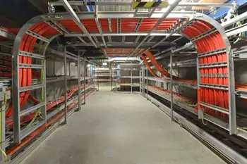
The use of ladder-type trays as raceways for insulated cables is becoming more prevalent. These raceways are being more heavily loaded with increasing number and size of cables being installed. With this growth in the use of tray, it is increasingly important that the tray and cable be installed within industry recognized practices. Discussed are the installation in tray of single and multi-conductor insulated cables with design limitations, example calculations, equipment, and equipment usage and its limitations. For an overview of tray system types and applications, see cable tray raceways for additional context.
For over thirty years, the use of a ladder-type tray as a rigid structural system for support of cables has grown dramatically. Accompanying this increase is the need for larger and longer cables to be installed. Designers and installers are continually faced with difficult challenges in the layout and installation of cable in tray. It is incumbent that pre-planning of an orderly sequence of events takes place to ensure that a successful installation occurs within recognized limits. Cable installed in tray is subject to many of the same considerations as cable being installed in conduit systems. Correctly calculated data and adherence to the design limits of the cables being installed with respect to tensions, sidewall pressures, and minimum bending radii increases the probability for a successful installation. Damage occurs more frequently as a result of improper handling during installation, or inadequate protection after installation. Cable tray layout must take into consideration the design limits of the cable. To minimize damage and verify integrity after installation, follow the practices outlined in cable handling and testing procedures for safer outcomes.

Installation Design Considerations and Formulas
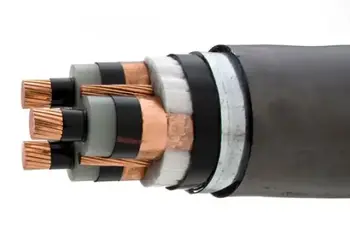
Selecting the correct conductor materials and insulation ratings starts with understanding cable families as summarized in Know Your Electrical Cables before applying these formulas.
Tensions
The maximum allowable pulling tension that can be applied safely to a cable varies with the size and material of the conductor, the number of cables, and the method of attachment between the pulling line and cable.
Commissioning teams often validate these limits through acceptance and maintenance checks such as those described in power cable test methods to confirm performance.
A. For pulling eyes and bolts the maximum tension is expressed as:
Tmax = .008 * N * A Eq. (1)
(For copper conductors and full hard drawn aluminum.)
In medium- and high-capacity corridors, copper conductors are frequently used in subterranean runs like those discussed under copper underground transmission for reliable delivery.
Tmax = .006 * N * A (For soft aluminum) Eq. (2)
Where
Tmax = Maximum allowable pulling tension in lbs/(kg)
N = Number of conductors
A = Conductor area in circular Mils (mm2)
.006 or .008 = Allowable stress per circular Mil (mm2) area for referenced metals.
For pulling eyes and bolts, the tension generated in a straight section of cable tray is expressed as:
Practical techniques for pulling setups, sheave placement, and crew coordination are detailed in installation of conductors and cables to help manage calculated forces.
T = L x w x f Eq. (3)
Where
L = The length of the cable tray section in feet (m)
w = The total weight of the cable being pulled in pounds (kg).
f = The coefficient of friction.
A. Range of .15 to .25 is recommended for the coefficient of friction. This coefficient is a function of the condition and alignment of sheaves.
Where tray runs experience dynamic loads or short-circuit forces, secure conductors with appropriately rated cable cleats to control movement.
B. For basket grips, the limit is 1000 lbs (453.6 kg/m) per grip or the value calculated in equation (1) whichever is smaller. This limit applies to a single conductor cable, a multi-conductor cable with a common overall jacket, two or three twisted cables, or paralleled cables using one grip. It is desirable to pull the cable by the conductors if this choice can be made rather than other type grips.
C. For conductor wedge-type compression grips, the grip manufacturer should be consulted for design limits of these devices. The same limits apply to these devices as pulling eyes and bolts.
Found In: Wire and Cable and Wiring Methods Handbook - Vol. 3
Think you know Wire and Cable? Take our quick, interactive quiz and test your knowledge in minutes.
Advantages To Instructor-Led Training – Instructor-Led Course, Customized Training, Multiple Locations, Economical, CEU Credits, Course Discounts.
Request For QuotationWhether you would prefer Live Online or In-Person instruction, our electrical training courses can be tailored to meet your company's specific requirements and delivered to your employees in one location or at various locations.