Thermography used to be expensive, difficult, and primarily used by large industrial facilities and the military. These days, it has become much more affordable, easier to use, and more broadly applied.
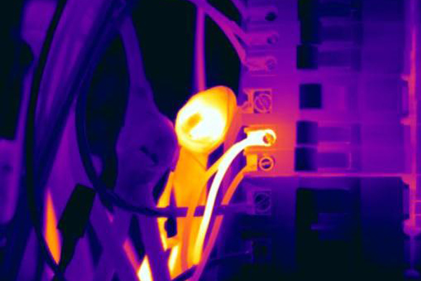
A thermal imager works by producing thermal (heat) pictures of the equipment. Electrical contractors typically use thermal imagers for predictive maintenance and troubleshooting, and sometimes during installation. For predictive maintenance, the contractor takes thermal images of key units (panels, drives, and motors) at least once a year if not more often, and compares those images with each visit. Hot or cold spots that were not previously evident may indicate problems that need to be investigated before they cause failure.
For troubleshooting, a thermal image of a malfunctioning unit can often identify the source of the problem—electrical hotspots reveal which phase or connectors to check, and motor hotspots can narrow it down to bearing and windings. Following repairs, follow up with another thermal image and verify that the component is no longer overheating or that something else is not now overheating, instead.
Today’s thermal imagers are compact and easy to use. For example, some thermal imagers include features that fuse a visual or visible light image with an infrared photo for better identification, analysis, and image management. To capture a specific thermal image, in most cases, simply squeeze the trigger. When work is completed, upload the images to the included software, analyze them more closely, and create reports documenting any findings. The dual images are accurately aligned heightening details, making it much easier to spot where further investigation is needed.
EMISSIVITY
When a technician reads surface temperature, he/she is actually measuring the infrared energy emitted by that object. The emissivity of a material determines how efficiently the surface emits energy. The typical emissivity of most organic materials and painted surfaces is about
0.95. However, certain materials, such as concrete and metals, are poorer emitters—their emitted energy does not accurately reflect their real surface temperature. The emissivity and reflected temperature values in the imager can be adjusted for accuracy to obtain thermal measurements of less efficient emitters. However, as emissivity values drop, more care will be needed and values below about 0.6 may be difficult in the field.
Emissivity values for many materials are published in charts and can be used as a guide. Ideally, measure the temperature of an object with a contact thermometer then adjust the emissivity of the imager for the same reading. Then, the technician knows the emissivity for future measurements.
LEVEL AND SPAN
When the image includes a wide range of temperatures, level and span adjustments can help technicians focus on the most important temperatures. Most users work in automatic mode where the thermal imager automatically assigns a temperature range based on the thermal scene in the viewfinder. If the imager senses a range from 80 degrees to 120 degrees, the camera will automatically adjust the temperature range to show that range.
If, however, the technician looks at a scene in automatic mode with a cooler object in the foreground and a hotter object of no interest in the background, the color palette will be spread across a wide range of temperatures and the resolution of the actual area of interest will be poor. In such cases, the technician can manually adjust the level and span to better view just the hot or cool object.
SOFTWARE
The technician will usually need software with any purchased thermal imager, so here are the key points to consider:


_1547716275.jpg)