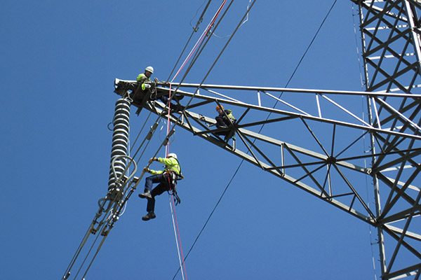
1. PERSONAL FALL ARREST SYSTEMS
(A) GENERAL TEST CONDITIONS
- Lifelines, lanyards, and deceleration devices should be attached to an anchorage and connected to the body-belt or body harness in the same manner as they would be when used to protect employees, except that lanyards should be tested only when connected directly to the anchorage, and not when connected to a lifeline.
- The anchorage should be rigid, and should not have a deflection greater than .04 inches (1 cm) when a force of 2,250 pounds (10.01 Kn) is applied.
- The frequency response of the load measuring instrumentation should be 100 Hz.
- The test weight used in the strength and force tests should be a rigid, metal cylindrical or torso-shaped object with a girth of 38 inches plus or minus 4 inches (96.5 cm plus or minus 10.16 cm).
- The lanyard or lifeline used to create the free fall distance should be the one supplied with the system, or in its absence, the least elastic lanyard or lifeline available to be used by the employee with the system.
- The test weight for each test should be hoisted to the required level and should be quickly released without having any appreciable motion imparted to it.
- The system’s performance should be evaluated, taking into account the range of environmental conditions for which it is designed to be used.
- Following the test, the system need not be capable of further operation.
(B) STRENGTH TEST
- During the testing of all systems, a test weight of 300 pounds plus or minus 5 pounds (136.08 kg plus or minus 2.27 kg) should be used. (See paragraph (4) above.)
- The test consists of dropping the test weight once. A new unused system should be used for each test.
- For lanyard systems, the lanyard length should be 6 feet plus or minus 2 inches (1.83 m plus or minus 5.08 cm) as measured from the fixed anchorage to the attachment on the body belt or harness.
- For rope-grab-type deceleration systems, the length of the lifeline above the center line of the grabbing mechanism to the lifeline’s anchorage point should not exceed 2 feet (0.61 m).
- For lanyard systems, for systems with deceleration devices which do not automatically limit free fall distance to 2 feet (0.61 m) or less, and for systems with deceleration devices which have a connection distance in excess of 1 foot (0.31 m) (measured between the centerline of the lifeline and the attachment point to the body belt or harness), the test weight should be rigged to free fall a distance of 7.5 feet (2.29 m) from a point that is 1.5 feet (45.72 cm) above the anchorage point, to its hanging location (6 feet (1.83 m) below the anchorage). The test weight should fall without interference, obstruction, or hitting the floor or the ground during the test. In non-elastic wire lanyard of sufficient length may need to be added to the system (for test purposes) to create the necessary free fall distance.
- For deceleration device systems with integral lifelines or lanyards which automatically limit free fall distance to 2 feet (0.61 m) or less, the test weight should be rigged to free fall a distance of four feet (1.22 m).
- Any weight which detaches from the belt or harness should constitute failure for the strength test.
(C) FORCE TEST GENERAL. THE TEST CONSISTS OF DROPPING THE RESPECTIVE TEST
WEIGHT ONCE. A NEW, UNUSED SYSTEM SHOULD BE USED FOR EACH TEST
- For lanyard systems. (i) A test weight of 220 pounds plus or minus three pounds (99.79 kg plus or minus 1.36 kg) should be used (see paragraph (4) above). (ii) Lanyard length should be 6 feet plus or minus 2 inches (1.83 m plus or minus 5.08 cm) as measured from the fixed anchorage to the attachment on the body belt or body harness. (iii) The test weight should fall free from the anchorage level to its handling location (a total of 6 feet (1.83 m) free fall distance) without interference, obstruction, or hitting the floor or ground during the test.
- For all other systems. (i) A test weight of 220 pounds plus or minus 3 pounds (99.79 kg plus or minus 1.36 kg) should be used (see paragraph (4) above). (ii) The free fall distance to be used in the test should be the maximum fall distance physically permitted by the system during normal use conditions, up to a maximum free fall distance for the test weight of 6 feet (1.83 m), except as follows: (A) For deceleration systems which have a connection link or lanyard, the test weight should free fall a distance equal to the connection distance (measured between the center line of the lifeline and the attachment point to the body belt or harness). (B) For deceleration device systems with integral life lines or lanyards which automatically limit free fall distance to 2 feet (0.61 m) or less, the test weight should free fall a distance equal to that permitted by the system in normal use. (For example, to test a system with a self-retracting lifeline or lanyard, the test weight should be supported and the system allowed to retract the lifeline or lanyard as it would in normal use. The test weight would then be released and the force and deceleration distance measured.)
- Failure. A system fails the force test if the recorded maximum arresting force exceeds 1,260 pounds (5.6 Kn) when using a body belt, or exceeds 2,520 pounds (11.21 Kn) when using a body harness.
- Distances. The maximum elongation and decelerationdistance should be recorded during the force test.
(D) DECELERATION DEVICE TESTS - GENERAL. THE DEVICE SHOULD BE EVALUATED
OR TESTED UNDER THE ENVIRONMENTAL CONDITIONS (SUCH AS RAIN, ICE,
GREASE, DIRT, TYPE OF LIFELINE, ETC.) FOR WHICH THE DEVICE IS DESIGNED
- Rope-grab-type deceleration devices. (i) Devices should be moved on a lifeline 1,000 times over the same length of line a distance of not less than 1 foot (30.48 cm), and the mechanism should lock each time. (ii) Unless the device is permanently marked to indicate thetype of lifelines which must be used, several types (different diameters and different materials) of lifelines should be used to test the device.
- Other-self-activating-type deceleration devices. The locking mechanisms of other self-activating-type deceleration devices designed for more than one arrest should lock each of 1,000 times as they would in normal service.
2. POSITIONING DEVICE SYSTEMS
(A) TEST CONDITIONS
- The fixed anchorage should be rigid and should not have a deflection greater than .04 inches (1.02 mm) when a force of 2,250 pounds (10.01 Kn) is applied.
- For lineman’s body belts and pole straps, the body belt should be secured to a 250 pound (113.4 kg) bag of sand at a point which simulates the waist of an employee. One end of the pole strap should be attached to the rigid anchorage and the other end to the body belt. The sand bag should be allowed to free fall a distance of 4 feet (1.22 m). Failure of the pole strap and body belt should be indicated by any breakage or slippage sufficient to permit the bag to fall free to the ground.
- For window cleaner’s belts, the complete belt should withstand a drop test consisting of a 250 pound (113.4 kg) weight falling free for a distance of 6 feet (1.83 m). The weight should be a rigid object with a girth of 38 inches plus or minus four inches (96.52 cm plus or minus 10.16 cm.) The weight should be placed in the waistband with the belt buckle drawn firmly against the weight, as when the belt is worn by a window cleaner. One belt terminal should be attached to a rigid anchor and the other terminal should hang free. The terminals should be adjusted to their maximum span. The weight fastened in the freely suspended belt should then be lifted exactly 6 feet (1.83 m) above its “at rest” position and released so as to permit a free fall of 6 feet (1.83 m) vertically below the point of attachment of the terminal anchor. The belt system should be equipped with devices and instrumentation capable of measuring the duration and magnitude of the arrest forces. Any breakage or slippage which permits the weight to fall free of the system constitutes failure of the test. In addition, the initial and subsequent arresting force peaks should be measured and should not exceed 2,000 pounds (8.9 Kn) for more than 2 milliseconds for the initial impact, nor exceed 1,000 pounds (4.45 Kn) for the remainder of the arrest time.
- All other positioning device systems (except for restraint line systems) should withstand a drop test consisting of a 250-pound (113.4 kg) weight falling free for a distance of 4 feet (1.22 m). The weight should be a rigid object with a girth of 38 inches plus or minus 4 inches (96.52 cm plus or minus 10.16 cm). The body belt or harness should be affixed to the test weight as it would be to an employee. The system should be connected to the rigid anchor in the manner that the system would be connected in normal use. The weight should be lifted exactly 4 feet (1.22 m) above its “at rest” position and released so as to permit a vertical free fall of 4 feet (1.22 m). Any breakage or slippage which permits the weight to fall free to the ground should constitute failure of the system.


_1547716275.jpg)