Hydroelectricity Explained

Hydroelectricity

Hydroelectricity converts hydropower into grid-ready electricity using dams, penstocks, turbines, and generators, enabling renewable baseload, pumped storage, high efficiency, and low emissions for resilient power systems with load balancing, frequency regulation, and strong capacity factors.


What Is Hydroelectricity?

Hydroelectricity is electricity generated by water turning turbines at dams, delivering low-carbon power to the grid.

✅ Converts hydraulic head and flow into alternating current.

✅ Uses synchronous generators, excitation, and step-up transformers.

✅ Supports grid inertia, regulation, and pumped-storage balancing.


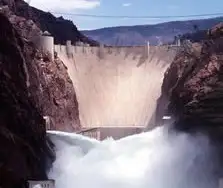
Hydroelectricity is another term for power generated by harnessing the power of damming rivers and moving water into generating plants. Not necessarily falling water, just moving water. There are many famous such Hydroelectricity stations in the world, not the least of them at Niagara Falls, Grand Coulee and Boulder Dam and the three gorges dam in China . In the past, small plants produced electric hydroelectricity. Now, they are massive in size and generation capcity as well as having large reservoirs. If there is a need for power electrical generation stations situated close to the point of consumption is ideal. These are just a few of the many examples of energy produced by falling water. On the other hand, a small mill set in the rapids of a fast-moving stream is also an example of it in action, on a lesser scale. The truth is that any steady current of flowing water from a river or other waterway can be converted to power. Of all the sources electricity from hydroelectricity, dammed reservoirs is one of the cleanest possibe ways to generate electricity to a million people, compared with nuclear power. For broader background on water safety and power concepts, the guide on water and electricity explains interactions, risks, and basic generation principles.


How is HydroElectricity Generated?

Hydroelectricity is generated or "manufactured" in large hydroelectric plants, (electrical generating stations) using the same basic principle as a small grist mill yet on a much larger and vastly improved scale for better efficiency, using pumped storage. These power plants contain electrical generators which are attached to massive turbine devices which spin at great speeds as a result of water rushing through them. These pump water power station turbines are much more efficient at extracting the kinetic energy from the moving water and converting that energy it into electrical production through these generators. To see how hydro fits within the wider energy landscape, review how electricity is generated across different prime movers and grid systems.

The amount of electricity from Hydroelectricity extracted from water as an energy source depends not only on the capacities of volume sent through a hydroelectric power plant but on the difference in height between the source and the water's outflow. This height difference is called the head. The amount of potential energy in water is directly proportional to the head and how much water is released. To obtain very high head, water for a hydraulic turbine may be run through a large pipe called a penstock. These relationships between flow, head, and output are core electricity generation principles that guide plant design and optimization.

For instance, energy is derived to make electricity water has to move from a higher elevation to a lower elevation through a large tube" otherwise known in technical terms as a "penstock". When the water reaches the end of the penstock, it turns a water wheel or "turbine" at enormous speeds. The turbine rotates, via a connected shaft to an electrical generator, and this generator creates electricity. It is the turbine and generator working in combination that converts "mechanical energy" into "electric energy". The water that makes this possible, is a renewable energy resource, just like the wind that turns the turbine attached to a generator. This mechanical-to-electrical conversion is a classic way to generate electricity efficiently when hydraulic conditions are favorable.

Hydroelectricity may be extracted from water but it depends not only on the volume of water but also on the difference in height between the top of the penstock and where the water spins the turbine. This difference in height is often referred to as the "head". From this "head", it can be determined the exact amount of potential energy that can be converted. Therefore, it is advantageous to build power dams as high as possible to convert the maximum energy from mechanical energy. Project planners evaluate head, flow duration, and dispatch needs in the context of overall electricity production targets and grid reliability.

While many hydroelectricity generating stations supply world power grids, some projects are created for private business purposes. For example, aluminium manufacturing companies require large amounts of power. And there are many other examples of industries that use hydroelectricity in their manufacturing operations. Industrial facilities often diversify procurement among various sources of electricity to balance costs, resilience, and sustainability goals.

While hydroelectricity in the United States seems relatively clean and safe in comparison to burning fossil fuels (coal or oil or natural gas), nearly all large hydroelectricity installations in North America have significant had impacts on nearby environmental habitats once they are brought online. This is because they significantly impede the flow of water in rivers and lakes at the point where the generating dam is installed In turn, this causes significant increases in water levels in corresponding upstream water systems while at the same time creating much lower water levels downstream. Mitigation strategies may include fish passages, adaptive flow management, and complementary alternative electricity options to reduce ecological disruption.

Related News

Electromagnetic Induction

Electromagnetic induction is the process of generating electric current by changing a magnetic field, forming the basis for transformers, generators, and electric motors in power generation and energy conversion systems.


What is Electromagnetic Induction?

Electromagnetic induction is a fascinating and vital concept shaping how we generate, transfer, and utilize electricity.

✅ Process where a changing magnetic field induces an electric current in a conductor

✅ Fundamental principle behind transformers, generators, and electric motors

✅ Essential for modern power generation, transmission, and energy conversion


Its underlying principles, Faraday's Law and Lenz's Law, explain the phenomena occurring when magnetic fields interact with conductors. At the same time, its various applications, such as electric generators, transformers, induction heating, and wireless charging, have revolutionized our daily lives. As we continue to explore and understand this intricacy, we can look forward to even more innovations and advancements in electricity and magnetism. Understanding Faraday's Law is essential to grasp how changing magnetic fields generate electricity through electromagnetic induction.


Fundamental Laws of Electromagnetic Induction

Faraday's Law of electromagnetic induction, invented by Michael Faraday, is a key principle that states that the induced EMF in a coil is proportional to the rate of change of the magnetic flux (dφ/dt) passing through the coil. The more rapidly the magnetic field changes, the higher the amount of voltage induced will be. This relationship between electricity and magnetism laid the foundation for the development of various electrical devices and systems. The relationship between electricity and magnetism forms the foundation of generators, transformers, and other key electrical systems.

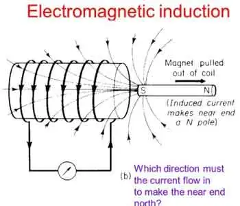
Lenz's Law, another crucial principle, explains the direction of the induced current. It states that the induced current will always flow in a direction that opposes the change in magnetic flux, acting as a stabilizing electromotive force. By combining Faraday's and Lenz's Law, we can better understand how it operates in real-world applications. For a deeper understanding of how voltage is produced in coils, explore the principles of Lenz's Law.


Core Applications: Generators and Transformers

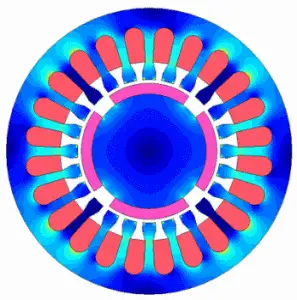
One notable application is the electrical generator, which converts mechanical energy into electrical energy. In a typical generator, a coil of wire rotates within a magnetic field, creating a changing magnetic flux. This change induces a voltage and current in the coil, generating electricity. Generators are commonly used in power plants, automobiles, and other devices requiring a continuous electrical supply. A three-phase transformer uses electromagnetic induction to efficiently transfer power between circuits at different voltages.

Another critical application is the transformer, which transfers electrical energy between circuits with different voltages. Transformers consist of two induction coils wrapped around a shared magnetic core. When an alternating current flows through the primary coil, it creates a magnetic field that induces a voltage in the secondary coil. By adjusting the number of turns in the coils, transformers can step up or down the voltage as needed for specific electrical systems.


Special Phenomena: Eddy Currents, Mutual Inductance, and Self-Inductance

Eddy currents are an intriguing aspect of electromagnetic induction. These currents form when a magnetic field changes, causing swirling, closed loops of electric current within a conductor. Eddy currents generate heat and can lead to energy losses in electrical systems, but they also have practical applications, such as in metal detectors and induction heating. Devices that use electromagnetic induction, such as electric motors, rely on core principles of inductance to regulate energy transfer.

Two critical aspects of electromagnetic induction are mutual inductance and self-inductance. Mutual inductance occurs when the current in one coil induces a voltage in a nearby coil due to their shared magnetic field. Self-inductance refers to a coil's ability to induce a voltage within itself when the current flowing through it changes. Understanding these concepts is crucial for designing and analyzing complex electrical circuits and systems.


Demonstrating the Principle: Coil and Magnet Interaction

In many cases, it involves the interaction of a coil and a magnet, either a permanent magnet or an electromagnet. A bar magnet, for example, may be moved near a coil, or the coil may be moved about the magnet. This motion changes the magnetic field and induces a voltage in the coil, demonstrating the dynamic relationship between electricity and magnetism. Learning the basics of electrical resistance helps explain how eddy currents generate heat in conductive materials.


Modern Impact and Emerging Technologies

It has an immense impact on modern life, from generating electricity in power plants to operating devices like transformers, electric motors, and wireless chargers. The principles of Faraday's Law and Lenz's Law help explain the complex phenomena that occur when magnetic fields interact with conductors. By harnessing these principles, scientists and engineers have created various practical applications that have revolutionized our daily lives.

Electromagnetic induction demonstrates the fundamental relationship between electricity and magnetism and is integral to many aspects of our modern world. Faraday's Law and Lenz's Law underpin this phenomenon, governing the induced voltage and current when magnetic fields change. The applications of electromagnetic induction range from electric generators and transformers to the study of eddy currents, mutual in influence and self-inductance. By understanding these principles, we can continue to innovate and develop new technologies to improve our daily lives and advance our understanding of the world.


Induction Heating

Electromagnetic induction heating is another practical application that relies on electromagnetic induction. This technology utilizes eddy currents to heat conductive materials, such as metals. By placing a conductive material within a rapidly changing magnetic field, eddy currents are generated within the material, producing heat due to their resistance. This heating method has been employed in various industrial processes, including metal hardening, welding, and cooking.

Wireless charging is an emerging technology that utilizes electromagnetic induction to transfer energy between two coils. When an electric current flows through the primary coil, it generates a magnetic field, which induces a voltage in the secondary coil, providing power to the device. This technology has seen increasing adoption in recent years, particularly for charging electric vehicles and smartphones, offering convenience and reduced dependence on cords and cables.


Related Articles


View more

Electricity Power Explained

Electricity power underpins voltage, current, and wattage in generation, transmission, and distribution across the grid, integrating AC/DC systems, transformers, generators, load management, power factor correction, and renewable energy for efficient, reliable supply.


What Is Electricity Power?

Electricity power is energy transfer rate: voltage times current, yielding watts in AC/DC systems.

✅ P = V * I; apparent, real, reactive power relationships

✅ Power factor improves efficiency and reduces I^2R losses

✅ Transformers step voltage for transmission efficiency


The make up of the electricity power sector has been in transition over recent history. In most provinces, there has been a transition from traditional electric utilities (which are mostly provincially-owned crown corporations) to private generation, transmission and distribution assets. For context, industry overviews such as electricity generation in Canada outline how policy and market structures influence capacity additions today.

In 2014, Canadian eutilities and industrials generators produced more than 639 terawatt hours of electricity. When it comes to hydroelectric power, Canada is the world's second largest producer. Hydroelectricity accounts for 59.3 per cent of Canada’s supply. Other energy sources that contribute to the transfer of energy include: coal, uranium, natural gas, petroleum and non-hydro renewable energy sources. About 67 per cent of Canada’s energy comes from renewable sources like wind, solar and hydroelectric power stations and 82% from non-greenhouse gas emitting sources. A breakdown of major fuels is available through sources of electricity for readers comparing provincial mixes.

Hydropower output is intrinsically linked to water availability and operations, and resources on water and electricity explain how hydrology and infrastructure shape generation profiles.

In 2014, almost 59 terawatt hours of electricity exported to the USA, while about 13 terawatt hours was imported from the United States. These trade patterns reflect how provinces balance load and generation portfolios, as noted in discussions of electricity supply dynamics under varying market conditions.

Canada's industrial sector is responsible for the largest share of electricity demand because there are a number of energy-intensive industrial activities like mining, oil and gas production, pulp and paper production, and other primary industry uses. Residential and commercial sectors consume much smaller quantities of electricity for lighting (light bulb), heating, and communications. Detailed consumption patterns can be explored in Canada's electricity demand by sector and region.

R&D programs aimed at maintaining the operating capability of the nation’s existing nuclear power plants and developing the next generation of nuclear technologies. Nuclear energy is the world’s largest source of emission-free electricity power. The Nuclear Energy program is working to develop cost-efficient technologies that further enhance nuclear safety, minimize the generation of nuclear waste, and further reduce the risk of proliferation. Within the broader generation portfolio, resources like nuclear are profiled in guides on how electricity is generated across different technologies.

To meet the rising demand of the 21st century, significant improvements in America’s electric system are necessary. Blackouts serve as a powerful reminder of the critical role electricity plays in the everyday lives of people.


Voltages, currents, power energy

When it comes to electric current, electrical voltage, electric circuit dynamics and energy powers, all rely on the flow of the electron. What this means is that power voltage feeds loads, solid state power load devices, and other loads that need electric power. Electric power is the rate at which that power is measured in watts or voltage in volts. There are various forms of energy measured in si unit: apparent power, reactive power, ac power, real power in watts, etc. For a refresher on fundamental concepts and terminology, see what is electricity to connect these quantities with practical applications.

Electrical Engineers and Scientists alike seek common views in order to develop new technologies for the storage of energy and the transmission of electric potential through power circuits that will contribute to energy efficiency of the electric industry. For instance, the copper wires used in typical transmission lines lose a percentage of the electricity passing through them because of resistance over long distances, which causes the wires to heat up. But "superconducting" materials have no resistance, and if they are used to transmit electricity in the future, very little of the electricity will be lost.


Related Articles

View more

Short Circuit Definition

Understanding the short circuit definition and associated risks is crucial for ensuring electrical safety in homes and workplaces. By knowing the common causes of short circuits and employing preventive measures such as regular inspections, proper installation, and protective devices like circuit breakers and GFCIs, we can minimize the dangers associated with short circuits and create a safer environment for everyone.

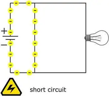
A short circuit phenomenon occurs in electrical circuits and poses potential safety hazards. To better understand the short circuit definition, one must first become familiar with the fundamentals of electrical circuits. An electrical circuit is a closed loop through which electrical current flows, and it consists of various components such as power sources, conductors, and electrical devices. A short circuit happens when an unintended, low-resistance path is formed within the circuit, causing a significant increase in current flow.


What are the different types of short circuit?

There are three main types of short circuits, each with unique characteristics and implications. These types are categorized based on the specific components of the short circuit within an electrical system. Here are the three types of short circuits:


Phase-to-Phase

This type of short circuit, also known as a line-to-line short circuit, occurs when two or more phases of an electrical system come into contact with each other. For example, this can happen when insulation between the phases is damaged or worn out, or due to a fault in the equipment or wiring. A phase-to-phase short circuit rapidly increases current flow between the affected phases, which can cause significant damage to the electrical system and generate considerable heat.


Phase-to-Neutral

A phase-to-neutral short circuit, sometimes called a line-to-neutral short circuit, occurs when a live conductor (phase) comes into contact with the neutral conductor. This can occur due to damaged insulation, loose connections, or faulty equipment. In a phase-to-neutral short circuit, the current flows between the affected phase and the neutral conductor, resulting in an increased current flow and potential damage to the electrical system.


Phase-to-Ground

This type of short circuit, also known as a ground fault, occurs when a live conductor (phase) comes into contact with a grounded object or the earth. For example, this can happen when insulation is compromised, equipment is faulty, or wiring is damaged. A phase-to-ground short circuit results in a sudden surge of current as electricity takes the path of least resistance through the ground, posing a risk of damage to electrical components, fire, and electrical shock.


Each of these types can cause significant harm to electrical systems and pose potential safety hazards. Therefore, maintaining proper insulation and connections within electrical systems and implementing protective devices such as circuit breakers and ground fault circuit interrupters (GFCIs) is crucial to minimize the risks. In addition, regular inspections and maintenance of electrical equipment are also essential in ensuring the safe operation of electrical systems.

Now that we've laid the groundwork, let's delve deeper into the definition. A short circuit is defined as an abnormal connection between two nodes in an electrical circuit, allowing an excessive amount of current to flow through a low-resistance path. This can lead to various problems, including damage to electrical components, increased risk of fire, and even electrical shock.

So, how do short circuits occur? Several common causes include damaged or frayed electrical wires, improper connections, or faulty insulation. In addition, when conductive materials come into contact, they can create an unintended path for electrical current. This leads to a significant increase in current flow, resulting in a short circuit.

The dangers associated with short circuits cannot be overstated. When a short circuit occurs, it can generate intense heat, which poses a significant fire risk. Additionally, the increased current can cause conductor failure and damage to electrical components, leading to malfunctions and even total system failure. Furthermore, if an individual comes into contact with a short-circuited component, they could suffer from electrical shock, which can sometimes be fatal.

Preventing short circuits is a vital aspect of maintaining electrical safety. One of the most effective prevention methods is ensuring proper installation and maintenance of electrical systems. In addition, regular inspections should be conducted to identify and repair damaged wiring or faulty connections. Installing overload protection devices, such as circuit breakers or fuses, can also help protect against short circuits. These devices are designed to detect and interrupt the excessive current flow, thus mitigating the risk of damage or injury.

Circuit breakers play a crucial role in safeguarding electrical systems from the effects of short circuits. These devices are engineered to detect an unusually high current flow, which could indicate a short circuit or another fault. Once detected, the circuit breaker will automatically interrupt the current flow, isolating the affected section of the circuit and preventing further damage or injury.

To further understand short circuits, it's important to distinguish them from ground faults. While both phenomena involve an abnormal connection within an electrical circuit, a ground fault is a specific type of short circuit that occurs when a live conductor comes into contact with a grounded object or the earth. This can lead to a sudden current surge and pose similar risks, such as fire and electrical shock. However, ground faults can be detected and mitigated using specialized devices called ground fault circuit interrupters (GFCIs).

Remember, always be vigilant when dealing with electrical systems. If you are uncertain about a potential issue or unsure how to handle a situation, consult a licensed electrician for assistance. Electrical safety is everyone's responsibility, and understanding definition is a fundamental step in preventing accidents and promoting a safe environment.

View more

Free Electricity Explained

Free electricity is power generated without fuel costs, typically from solar or wind sources. After setup, systems like solar panels can reduce or eliminate bills through net metering, helping promote sustainability and energy independence for homes and businesses.


What is Free Electricity?

Free electricity refers to energy that costs nothing to generate after initial setup, typically utilizing natural sources.

✅ Harnesses renewable energy sources like solar panels and wind turbines

✅ Reduces or eliminates long-term electricity costs

✅ Promotes sustainable and eco-friendly living solutions


The Reality of Free Electricity

True “free electricity” does not exist in the sense of unlimited, no-cost power available without investment. However, generating your electricity at home through solar panels or small wind systems can reduce your reliance on the power grid and lower your energy bills significantly, sometimes to zero. This cost reduction is what many people mean when they refer to "free electricity."

Purchasing and installing a solar power system is not free, but it pays off over time. It’s a long-term investment that benefits both the environment and your finances. Some homeowners even reach the point where their solar systems generate more electricity than they use.

In such cases, through a policy known as net metering, these homeowners can send excess electricity back to the power grid and receive compensation from their utility company.


What is Net Metering?

Net metering is a billing arrangement that allows consumers who generate their own electricity to send excess power back to the grid and receive credit for it. Here’s how it works:

  • Net metering allows you to sell the electricity produced by a solar system on your home back to the electric power grid.

  • Net Metering occurs when your meter spins backwards as solar electricity is being produced, storing the excess energy on the grid.

  • Once energy is actually being consumed, your meter spins forward to collect the energy that has been saved on your electric power grid.

  • For the energy that you do not consume, the electric utility will compensate you. If you get paid enough money from the electricity that you don't use and sell to them, then that profit can be used to pay for your existing consumption, making it essentially free electricity.

Some utilities offer cash payments for the surplus, while others provide energy credits that reduce your bill. Either way, your electricity costs can be significantly reduced—and in some cases, essentially eliminated.


Key Considerations for a Free Electricity System

A few things to watch out for when choosing to invest in a Free Electricity solar power system.

  • You must conserve your energy consumption to ensure that you don't exceed the amount of solar energy produced.

  • By exceeding the amount of power generated many times for the grid or saved, you are then charged regular rates for electricity provided by your electric utility.

  • You must watch your solar energy production. Keep track of the daily energy production of your system.

  • Check your utility bill each month to ensure that you are credited or reimbursed for any and all extra energy generated.

  • To control your electricity usage, consider using a time-of-use electric meter to further capitalize on your investment.


Utility Policies Vary

Not all utility companies offer generous net metering. Some may only provide energy credits, while others pay wholesale rates for your excess electricity. It's essential to check with your local utility to understand how they handle customer-generated power.

While the term “free electricity” is somewhat misleading, it does accurately reflect the very real possibility of generating low-cost or no-cost power after your initial system is installed. Through renewable energy systems and programs like net metering, homeowners can reduce or eliminate energy bills and make a lasting contribution to a cleaner, more sustainable future.


Related Articles


View more

Resistances in Parallel

Resistances in parallel share voltage, add conductances, and reduce equivalent resistance; apply Ohm's law, current division, and circuit analysis to compute total R, branch currents, and power distribution in multi-branch networks.


What Are Resistances in Parallel?

Parallel resistors share voltage; total resistance decreases by summing conductances (1/R).

✅ Equivalent 1/Rt = sum(1/Ri); lower than smallest branch

✅ Same voltage across branches; currents split by conductance

✅ Use Ohm's law and current division to size components, power


Resistances in parallel is a common term used in industrial, commercial, and institutional power systems. Therefore, a good understanding of working with resistors in parallel and calculating their various parameters is crucial for maintaining safe and efficient operations. For foundational context, see this overview of electrical resistance for key definitions applied throughout.

It means that when resistors are connected in parallel, they share the same voltage across them. Hence, this means that the resistances are in parallel. This is because the total resistance of the resistors in parallel is less than that of any individual resistor, making it a useful configuration for reducing resistance and increasing current in a circuit. A clear grasp of electrical resistance helps explain why parallel branches draw more current.

Adding more resistors in parallel reduces the circuit's total resistance, increasing the current. However, adding too many resistors in parallel can overload the circuit and cause it to fail. Engineers often verify safe loading using the resistance formula to predict current increases.


Understanding Resistances in Parallel

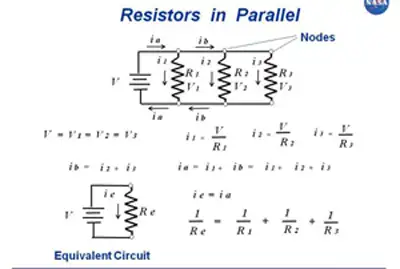
They refer to the configuration in which two or more resistors are connected side by side across the same voltage points in an electrical circuit. In this arrangement, the voltage across each resistor is the same, while the current is divided among the resistors according to their resistance values. This configuration is commonly used in circuit analysis to simplify complex circuits and determine the equivalent parallel resistance.

When simplifying networks, computing the equivalent resistance streamlines analysis and component selection.


Calculating the Equivalent Resistance

To calculate the equivalent resistance of resistances in parallel, the reciprocal of the equivalent resistance (1/Req) is equal to the sum of the reciprocals of the individual resistances (1/R1 + 1/R2 + ... + 1/Rn). This formula is crucial in resistance calculation and helps engineers design efficient power systems that meet the desired voltage drop and current distribution requirements. A comparable reciprocal relationship appears when evaluating capacitance in series under similar analysis methods.

To calculate the total resistance of resistors in parallel, the reciprocal of each resistor is added together, and then the result is inverted to give the total resistance. This can be represented mathematically as:

1/Rt = 1/R1 + 1/R2 + 1/R3 + ...

where Rt is the total resistance and R1, R2, R3, etc. are the individual resistors.


Five resistors R(1) through R(5), connected in parallel, produce a net resistance R.


In a circuit with resistors in parallel, the current is divided among the resistors according to their individual resistance values. This is known as the current division, and it can be calculated using Ohm's law and the circuit's total resistance. The formula for calculating the current through each resistor in parallel is:

I1 = (V/R1) * (R2/(R2 + R3)) I2 = (V/R2) * (R1/(R1 + R3)) I3 = (V/R3) * (R1/(R1 + R2))

where I1, I2, and I3 are the currents through each resistor, V is the voltage across the circuit, and R1, R2, and R3 are the individual resistors.

Simplifying a circuit with resistors in parallel involves finding the equivalent resistance of the circuit. This is the resistance value that would produce the same current as the original parallel circuit, and it can be calculated using the reciprocal formula:

1/Req = 1/R1 + 1/R2 + 1/R3 + ...

where Req is the equivalent resistance.


Impact on Total Resistance

In a parallel configuration, adding more resistors decreases the total resistance. The reason is that the current has multiple paths to flow through, reducing the overall opposition to current flow. This characteristic is particularly useful in designing power supply systems, where lower resistance is desired to minimize energy losses and improve system efficiency. By contrast, capacitance in parallel increases as components are added, offering a helpful design analogy.


Practical Applications

They are employed in various real-life circuits and power systems. For instance, they are commonly found in circuit simulations, power distribution systems, and load balancing applications. In industrial settings, a parallel resistor calculator is often used to measure multiple current paths for fault protection and redundancy. In commercial and institutional power systems, parallel configurations are employed to manage load distribution and ensure system reliability.


Differences between Parallel and Series Connections

In a series circuit, resistors are connected end-to-end, and the current flows consecutively from the source of each resistor. The total resistance in a series circuit equals the sum of individual resistances, and the voltage drop across each single resistor is different. In contrast, they share the same voltage, and the total resistance decreases as more resistors are added. Identifying these connections in a circuit diagram is crucial for proper circuit analysis and design. For direct comparison of methods, review resistance in series to see how sums differ from reciprocals.


Combining Resistances in Parallel and Series

They can be combined with resistances in series within the same circuit. In such cases, equivalent resistances for both parallel and series sections are calculated separately. Then, the total resistance is determined by adding the equivalent resistances of the series and parallel sections. This approach helps engineers analyze complex circuits and design efficient power systems.

They are crucial to industrial, commercial, and institutional power systems. Understanding how to calculate the total resistance, current distribution, and power dissipation of resistors in parallel is essential for maintaining safe and efficient operations. In addition, engineers can optimize their designs for optimal performance by using circuit simulation software and other tools.


Related Articles

View more

Electricity Terms Explained

Electricity terms explain voltage, current, resistance, impedance, power factor, frequency, AC/DC, circuits, transformers, and load. Master key definitions to analyze systems, size conductors, mitigate harmonics, and ensure safety compliance.


What Are Electricity Terms?

Standardized definitions for voltage, current, resistance, impedance, and power factor used in electrical engineering.

✅ Define units, symbols, and formulas per IEEE/IEC standards

✅ Clarify AC/DC behavior, phasors, impedance, and power factor

✅ Aid circuit analysis, sizing conductors, and safety compliance


Here are the top 50 commonly used electricity terms that are essential for understanding electrical systems, devices, and concepts: For a broader glossary with context and examples, see the curated list at Electrical Terms by Electricity Forum for deeper reference.

Voltage (V) – The electrical potential difference between two points in a circuit. Understanding how potential difference relates to the nature of electricity is clarified in this overview of what electricity is and how it behaves.

Current (I) – The flow of electric charge, measured in amperes (A). A concise explanation of electricity as a physical phenomenon is given in this definition of electricity for foundational understanding.

Resistance (R) – Opposition to current flow, measured in ohms (Ω).

Power (P) – The rate of doing work or transferring energy, measured in watts (W).

Ohm's Law – The relationship between voltage, current, and resistance. For a step-by-step refresher on the relationships among voltage, current, and resistance, explore this basic electricity guide to connect theory with practical examples.

Alternating Current (AC) – Electric current that reverses direction periodically.

Direct Current (DC) – Electric current that flows in one direction only. For a side-by-side comparison of waveform behavior, applications, and conversion methods, review the differences between AC and DC to strengthen conceptual understanding.

Frequency (f) – The number of cycles per second in AC, measured in hertz (Hz).

Impedance (Z) – The total opposition to current flow in an AC circuit, combining resistance and reactance, measured in ohms.

Capacitance (C) – The ability to store electrical energy in an electric field, measured in farads (F).

Inductance (L) – The ability of a conductor to induce a voltage when current changes, measured in henries (H).

Power Factor (PF) – The ratio of real power to apparent power, indicating the efficiency of a system.

Real Power (P) – The actual power consumed to perform work, measured in watts.

Apparent Power (S) – The total power in a system, combining real and reactive power, measured in volt-amperes (VA).

Reactive Power (Q) – Power in AC circuits that does not perform useful work, measured in volt-amperes reactive (VAR).

Load – The device or equipment that consumes electrical power.

Short Circuit – An abnormal connection between two points in a circuit, causing excessive current flow. To ground this topic in fundamentals, revisit what an electrical circuit is before examining fault conditions.

Overload – A condition where a circuit or device exceeds its rated current capacity.

Circuit Breaker – A protective device that interrupts the flow of current when an overload or short circuit occurs.

Fuse – A protective device that melts to break the circuit when excessive current flows.

Grounding (Earthing) – Connecting parts of an electrical system to the Earth to ensure safety.

Transformer – A device that transfers electrical energy between two or more circuits through electromagnetic induction.

Conductor – A material that allows the flow of electrical current, typically copper or aluminum.

Insulator – A material that resists the flow of electric current, such as rubber or plastic.

Phase – The distribution of alternating current electricity into separate waveforms, often used in three-phase power systems.

Watt (W) – The unit of power, equivalent to one joule per second.

Kilowatt (kW) – A unit of power equal to 1,000 watts.

Megawatt (MW) – A unit of power equal to 1 million watts.

Voltage Drop – The reduction in voltage across a component or conductor in an electrical circuit.

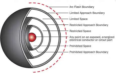
Arc Flash – A dangerous condition associated with the release of energy caused by an electric arc.

Resistor – A component that opposes the flow of current, used to control voltage and current in circuits.

Diode – A semiconductor device that allows current to flow in one direction only.

Rectifier – A device that converts AC to DC.

Inverter – A device that converts DC to AC.

Contactor – An electrically controlled switch used to control a power circuit.

Relay – A switch operated by an electromagnet, used for controlling circuits.

Switchgear – Equipment used to switch, control, and protect electrical circuits.

Distribution System – The system of wires and equipment that delivers electricity from substations to consumers.

Neutral – A conductor that carries current back to the source in an electrical system.

Busbar – A conductor used to distribute power from one source to multiple circuits.

Overcurrent Protection – Devices like fuses and circuit breakers designed to protect circuits from excessive current.

Phase Angle – The angular displacement between voltage and current waveforms in AC circuits.

Power Supply – A device that provides the necessary electrical power to a circuit or device.

Generator – A device that converts mechanical energy into electrical energy. This ties directly to how electrical energy is produced, transferred, and ultimately consumed.

Motor – A device that converts electrical energy into mechanical energy.

Frequency Converter – A device that changes the frequency of AC power.

Power Grid – A network of transmission lines, substations, and power stations for distributing electricity.

Service Panel – The central distribution point for electrical circuits in a building, containing circuit breakers or fuses.

Utility Transformer – A transformer that steps down high voltage for distribution to consumers.

Harmonics – Distortions in the electrical waveform that can affect power quality.

These terms cover a wide range of concepts from basic electrical theory to components and safety practices in electrical systems.


Related Articles

View more

Sign Up for Electricity Forum’s Newsletter

Stay informed with our FREE Newsletter — get the latest news, breakthrough technologies, and expert insights, delivered straight to your inbox.

Electricity Today T&D Magazine Subscribe for FREE

Stay informed with the latest T&D policies and technologies.
  • Timely insights from industry experts
  • Practical solutions T&D engineers
  • Free access to every issue

Live Online & In-person Group Training

Advantages To Instructor-Led Training – Instructor-Led Course, Customized Training, Multiple Locations, Economical, CEU Credits, Course Discounts.

Request For Quotation

Whether you would prefer Live Online or In-Person instruction, our electrical training courses can be tailored to meet your company's specific requirements and delivered to your employees in one location or at various locations.